 |
| |||||||||||||||||||||||||||||||||||
Institut f�r berufliche Entwicklung e.V.
Berlin
Original title:
Arbeitsmaterial f�r den
Lernenden
“Arbeiten an Langlochfr�smaschinen”
Author: Johannes Schollbach
First Edition © IBE
Institut f�r berufliche Entwicklung e.V.
Parkstra�e
23
13187 Berlin
Order No.: 93-35-3409/2
|
| |||||||||||||||||||||||||||||||||||
1. The Purpose of Drilling and Cutting with Long-hole Cutters
Long-hole cutting machines (also called longitudinal drilling machines) are applied for drilling of round-hole bores and for drilling and cutting of long holes. According to the type of the machine you can reach maximum bore depths of 200 mm and maximum lengths of the long holes of 200 mm. The diameter of the tools can be up to 25 mm.
Round bores and long holes are the basis of wooden joints: e.g. a doweled groove, a doweled frame joint, a caulked frame joint or cutting-outs for placing mountings.
Round bores and long holes can be manufactured with long-hole cutters across and with the grain of the pieces of work.
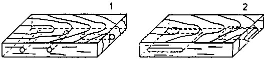
Figure 1 - Working on
long-hole cutting machines
1 round bores, 2 long holes
What is the purpose of drilling with a long-hole cutting
machine?
______________________________________________
______________________________________________
______________________________________________
What is the purpose of drilling and cutting with a long-hole
cutting
machine?
______________________________________________
______________________________________________
______________________________________________
|
| |||||||||||||||||||||||||||||||||||
2. The Construction of a Long-hole Cutting Machine
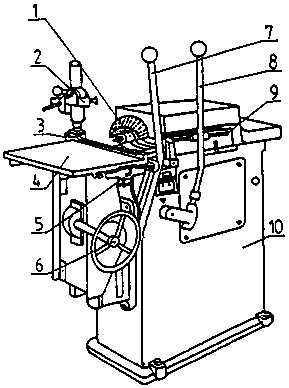
Figure 2 - Construction of a
long-hole cutting machine
1 bore chuck with safety basket, 2 fixture, 3 stop edge, 4 working table, 5 stops for fixing the cutting length, 6 hand wheel for adjusting the table height, 7 cutting lever (cross feed), 8 drilling lever (axial feed), 9 stop for fixing the bore depth, 10 stand
The stand
The stand accomodates the motor with the bore shaft and the bore chuck which can be moved in axial direction by a lever. The length of the axial movement determines the bore hole depth and can be fixed by a stop. The working table with the movement mechanism and the lever for the cross feed are fixed on the front side of the stand. The working table can be adjusted in height by a hand wheel.
The working table
The piece of work is clamped on the working table. The working table with the fixture moves on a guideway. The cross feed is carried out by a lever which determines the length of the long hole. The length of the cross feed can be adjusted by two stops.
The stop edge
The stop edge is fixed at a right angle (90°) to the axis of the bore shaft. Fixing the piece of work at that edge the right angularity of the round bore or of the long hole towards the edge of the piece of work is guaranteed.
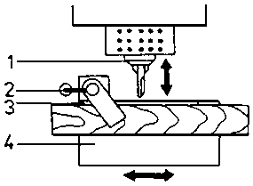
Figure 3 - Fastened wooden
boards
1 bore chuck, 2 fixture, 3 stop edge, 4 working table
The fixture
With this machine type the fixture has got an eccentric lever which clamps the piece of work with its pressure plate onto the working table.
Safety devices
Motor and bore shaft are covered. The bore chuck is smooth without projecting edges. A cover basket is placed over the bore chuck.
The fixture should be regularly checked for operation!The bore chuck and the tool shanks should be kept clean, as well as the surface of the machine table and the stop edge!
The machine should be lubricated according to a lubrication plan regularly!
What is the working table used
for?
______________________________________________
______________________________________________
______________________________________________
Why has the working table got a
fixture?
______________________________________________
______________________________________________
______________________________________________
Why has the working table got a stop
edge?
______________________________________________
______________________________________________
______________________________________________
How can the length of the cross feed of the working table be
fixed?
______________________________________________
______________________________________________
______________________________________________
|
| |||||||||||||||||||||||||||||||||||
3. The Tools
For drilling of round bores twist drills with a roof-shaped point or with a centre point are applied. The spiral shaped cutting notches cause a fast throwing out of the shavings. The centre point supports the guideway of the driller.
An especially good guideway with simultaneously clean bore edges without torn out particles is reached by a twist drill with a staggered centre point where the external edges of the main cutting edges are in the cut first and thus support the guideway of the driller.
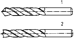
Figure 4 - Twist driller
1 with roof shaped point, 2 with staggered centre point
For cutting of long holes long-hole cutters (also called longitudinal drillers) with straight lengthwise cutting edges, one or two cutting notches and front cutting edges are applied. The straight lengthwise cutting edges cause the main cutting off. Because straight cutting notches are throwing out shaving worse than the spiral shaped ones deep cuttings are to be carried out with a long-hole cutter always in several steps.
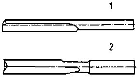
Figure 5 - Long-hole cutter
1 with one cutting notch, 2 with two cutting notches
Clean the tools carefully from resin, varnish and glue after application!For cleaning use solvents only, no metallic auxiliaries are to be applied!
Keep the tool in containers to protect the cutting edges against any kind of damage!
Which tool is mainly applied for drilling of round
bores?
______________________________________________
______________________________________________
______________________________________________
What is the purpose of the centre point of the
driller?
______________________________________________
______________________________________________
______________________________________________
Which tool is applied for drilling and cutting of long
holes?
______________________________________________
______________________________________________
______________________________________________
|
| |||||||||||||||||||||||||||||||||||
4. The Operation of the Long-hole Cutting Machine
Switching on the machine the bore chuck with the clamped tool is set into rotation, depending on the type of the machine from 1400 up to 11000 revolutions per minute. Now the drilling tool is pressed against the piece of work. By shaving off the piece of work round bores and long holes across and with the grain of the wood are manufactured.
Round bores up to a maximum depth of 200 mm are drilled by the axial movement of the bore shaft.
Long holes up to a maximum length of 200 mm are manufactured by lining up several round bores and cutting out the remaining wood stays.
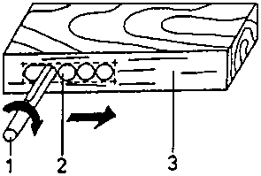
Figure 6 - Cutting out of lined
up round bores to form a long hole
1 long-hole cutter, 2 round bores, 3 wooden board
In which way are manufactured long holes with long-hole cutting
machines?
______________________________________________
______________________________________________
______________________________________________
|
| ||||||||||||||||||||
Working on Long-hole Cutting Machines - Course: Mechanical woodworking techniques. Trainees' handbook of lessons (Institut f�r Berufliche Entwicklung, 12 p.)
5. Technological Processes of Drilling and Cutting
5.1. The Manufacturing of Round Bores
Marking the piece of work
According to the measures taken from the technical drawing the bore centres are marked and punched with the awl so that the bore point can be placed precisely when drilling.
Be careful when handling the awl!Risk of accident!
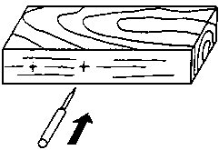
Figure 7 - Marking and
punching of the bore centres
Clamping the drill
After the selection of the necessary twist drill the latter is clamped in the bore chuck where the shank is placed in the bore chuck to the stop and clamped.
Pay attention to a secure clamping and to true running!Only tools with an undamaged shank should be applied!
Adjusting the bore depth
The necessary bore depth is adjusted on the stop.
Clamping the piece of work
The piece of work is placed on the stop edge of the working table and clamped with the fixture.
Check for secure clamping!
Adjusting the table height
The working table is adjusted with the hand wheel till the pre-punched bore centre of the piece of work corresponds with the height of the bore point.
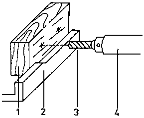
Figure 8 - Adjusting the table
height
1 wooden board with marked and pre-punched bore centres, 2 stop edge, 3 drill, 4 bore chuck
Drilling
The machine is switched on, now the drilling tool is pressed against the piece of work with the lever until stop the stops the axial movement. Now the required bore depth is reached.
When drilling the axial feed is carried out with the right hand while the left hand has to ensure the adjustment of the piece of work on the bore hole centre with the cross feed.
Please do wear a head cover and tight-fitting clothes!Do not grip with your hand over the bore chuck - risk of injuries!
Switching off and checking
After having resed the drill the machine is switched off. After removing the shavings the quality of the bore is checked with suitable measuring means.
Why must the bore centres be pre-punched after
marking?
______________________________________________
______________________________________________
______________________________________________
What should be payed attention to when clamping the
drill?
______________________________________________
______________________________________________
______________________________________________
What is the necessary bore depth fixed
with?
______________________________________________
______________________________________________
______________________________________________
How can you find out if the right table height is
adjusted?
______________________________________________
______________________________________________
______________________________________________
How is the drilling operation carried
out?
______________________________________________
______________________________________________
______________________________________________
5.2. The Manufacturing of Long-holes
Marking the piece of work
With single manufactured pieces of work the form of the long hole is marked in width and length. Now single bores lined up side by side filling out the long hole are pre-punched according to the bore diameter.
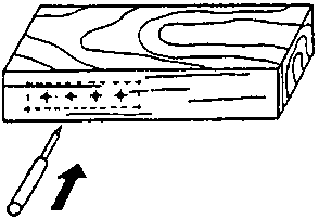
Figure 9 - Marking the long
hole and punching the bores
Clamping the long-hole cutting tool
The long-hole cutter is clamped in the bore chuck securely.
Check for secure clamping!
Adjusting the long hole's depth
The necessary depth of the long hole is adjusted on the stop - with the first cutting of deep long holes the total depth is not fixed yet.
Clamping the piece of work
The piece of work is placed on the slop edge of the working table and clamped securely with the fixture.
Check for secure clamping!
Adjusting the table height
The working table is adjusted with the hand wheel so that the bore centres correspond with the centre of the long-hole cutter. The table alignment should correspond with the alignment of the long hole.
Adjusting the length of the long hole
This length is adjusted by two stops. When manufacturing several pieces of work of the same type an extra stop chunk is fixed on the working table, so the marking of the long hole can be dropped and the dimensional accuracy is ensured. The stops are adjusted once for the first piece of work after which many pieces of work of the same type can be manufactured without time wasting marking and adjusting jobs being necessary.
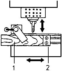
Figure 10 - Fastening the
wooden board with the help of a stop chunk
1 wooden board, 2 stop chunk
Drilling and cutting
The machine is switched on and now the single bores lined up side by side are drilled out step by step. With the last bore operation the stop should be adjusted for the final depth of the long hole.
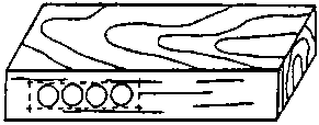
Figure 11 - Single bores to
fill the long hole
Finally the remaining wooden stays are cut off with the cross feed of the working table. With deep long holes the cutting should also be carried out in several steps in order not to overstress the cutting tool.
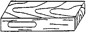
Figure 12 - Finish-cut long
hole
Switching off and checking
After having reset the long-hole cutter the machine is switched off. After removing the shavings the quality of the long hole is checked.
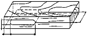
Figure 13 - Checking the long
hole
How do you mark single manufactured pieces of work for long-hole
cutting?
______________________________________________
______________________________________________
______________________________________________
How do you adjust the length of the long hole if several pieces
of work of the same type are to be
manufactured?
______________________________________________
______________________________________________
______________________________________________
Why must drilling and cutting of deep long holes be carried out
in
steps?
______________________________________________
______________________________________________
______________________________________________