 |
| ||||||||||||||||||||||||||||||||||||||||||||||||||||||||||||||||||||||||||||||||||||||||||
Institut f�r berufliche Entwicklung e.V.
Berlin
Original title:
Lehrgang Methodische Anleitung f�r
den Lehrenden
“Manuelle Werkstoffbearbeitung/Metall”
First edition © IBE
Institut f�r berufliche Entwicklung e.V.
Parkstra�e
23 13187 Berlin
Order No.: 90-32-0001/2
|
| ||||||||||||||||||||||||||||||||||||||||||||||||||||||||||||||||||||||||||||||||||||||||||
Introduction
The present guide shall help the instructor to accomplish the practical. Locational training by giving practical recommendations as to the
- preparation,
- accomplishment and
- review of the practical vocational lessons.
At the beginning of the methodical guide the instructor is informed of the aims and contents of the course. The guide also states the previous knowledge required for acquiring the working techniques of machining of material. The emphasis is on the recommendations of didactic and methodology of the practical vocational lessons. The recommendations suggest the instructor how to plan and prepare the lessons. Possible forms and methods of accomplishing the instructions and exercises are also explained.
The last section deals with the peculiarities of the individual training units. It also contains a summary of the necessary teaching aids and working tools to facilitate organizing the course.
A methodically arranged complex of questions and answers shall help the instructor to test the know ledge of the trainees.
|
| ||||||||||||||||||||||||||||||||||||||||||||||||||||||||||||||||||||||||||||||||||||||||||
1. Aims and contents of the course
On completion of this training course the trainees should have the necessary knowledge, abilities and skills to work with
- engine lathes,
- horizontal or vertical milling machines,
- horizontal shaping machines and
- boring/drilling machines.
This implies that the trainees
- are able to decide on the purpose and application of the relevant machine and technique,- are capable of setting up, operating, servicing and maintaining the machines and know the construction of the machines,
- have knowledge of how to determine the cutting values, such as speeds, feeds and stroke length,
- are able to select the proper tools and accessories for setting up the machines and know the construction of the different types of tools and accessories,
- have knowledge of how to meet the safety requirements in machining of material.
The course comprises the following training units (TU):
1st TU: Measuring and Testing
2nd TU: Marking and Punch Marking
3rd TU: Hammering and Marking
4th TU: Manual Sawing
5th TU: Filing
6th TU: Scraping of Plane Surface
7th TU: Drilling, Counterboring and Countersinking
8th TU: Manual Reaming
9th TU: Manual Thread Cutting
To successfully acquire the skills of these working techniques, the trainees must have previous knowledge of and master the basic skills in the working techniques of manual working of material. In addition, they should have basic knowledge of engineering drawing to be able to “read” the working drawings.
|
| ||||||||||||||||||||||||||||||||||||||||||||||||||||||||||||||||||||||||||||||||||||||||||
2. Organizational preparation of training
In order to ensure that the instructions, demonstrations and exercises go off smoothly, the training must be well prepared. The following is to be made available:
Classroom and workshop
Though the instructions could be given in the workshop, it is better to do it in a room where the trainees have adequate facilities to sit and write.
If a daylight projector shall be used, a bright projection area and electric supply are required.
The demonstrations of the working techniques, followed by exercises, are to be done in the workshop directly on the relevant machine. One machine with the necessary cutting and operating tools, measuring and testing tools and accessories should be available for each trainee. The necessary working tools, related to the “Instruction Examples for Practical Vocational Training”, are summarized in the “Methodical Guide for Instructor”.
Teaching aids
Sufficient copies of the “Trainees’ Handbook of Lessons” equalling the number of trainees are to be made available. The “Trainees’ Handbook of Lessons” is mainly used in the introductory instruction for introduction and recapitulation. It explains the technical knowledge of one training unit, which is absolutely necessary for mastering the relevant technique, in a clearly arranged and easily conceivable way. Many illustrations add up to better understanding. Tasks and questions are included to recapitulate, strengthen and test the knowledge acquired. But they may also be used by the trainees for acquiring the knowledge by themselves. A summary of all questions is contained in a complex of questions and answers in the present methodical guide in the sub-section of the relevant training unit. Tasks and questions included in the “Trainees’ Handbook of Lessons” are marked with “A”. Sufficient copies of the “Instruction Examples for Practical Vocational Training”, depending on the number of trainees, are to be made available. They explain the technology for practising the examples, supplemented by working drawings. By means of the “Instruction Examples...” workpieces can be produced and working algorithms practised to develop essential practical skills. Based on the “Instruction Examples...”, the availability of the materials and necessary working tools can be checked and arranged by the trainees themselves.
The “Instruction Examples...” of each training unit are arranged with increasing level of difficulty and should be followed in the sequence given. The textbooks
- “Basic Vocational Knowledge - Working of Metal”- “Formulas and Tables - Metal”
- “Machine Elements and Assemblies and their Installation”
can be used by the instructor for the instructions to consolidate knowledge and refresh basic knowledge.
The textbook “Formulas and Tables - metal” is particularly recommended for exercises of technical calculations.
All tools and accessories required for the working technique are to be made available as visual and/or demonstration aids. Various workpieces related to the conditions of the relevant factory are also to be made available for demonstration.
If transparencies shall be used, the daylight projector is to be checked for serviceability and the transparencies are to be checked for completeness. It is recommended to use the series of transparencies “Manual Working of Material” consisting of 37 transparencies (see Methodical Guide for Instructor).
Blackboard drawings are to be prepared prior to the instructions.
If further teaching aids are available, the instructor can complete the lists in “Methodical Guide for Instructor”. This will give him a comprehensive survey and facilitate the preparations for the instructions.
Working tools and materials
The trainees’ working places are to be checked for neatness, serviceability and completeness of the working tools and materials.
The completeness of the required technological documents (drawings, instruction examples for the relevant working technique) is to be ensured. Tests and/or recapitulations are to be prepared. The materials required for the exercises are specified in the relevant “Instruction Examples for Practical Vocational Training” - including the required dimensions. In a few cases the raw materials are to be made available in a certain stage of prefabrication that is to be prepared on advance.
|
| ||||||||||||||||||||||||||||||||||||
Manual Working of Material/Metal - Course: Manual working of metal. Methodical course-guide for instructors (Institut f�r Berufliche Entwicklung, 218 p.)
3. Accomplishment of the training
3.1. General recommendations for the procedure of the course
The training course proceeds in the succession of the individual training units. The training units “Setting up and operation” should always be started with, since they will impart the basic knowledge required for the other training units. The training should then proceed with the training units according to the serial number of the training units. The knowledge and skills in the relevant working technique should be taught by an alternation of instructions and exercises. The instructions shall teach the knowledge required for accomplishing the working technique. In the exercises to follow the trainees shall put into practice the theoretical knowledge acquired. Practising of the work routines should take most of the time available for training and go on until a specified level of perfection has been reached. The practical exercises are to be considered the heart of the training. At the end of the exercises each trainee should be informed of the level of skills developed. Therefore, the following procedure of teaching a working technique is recommended to the instructor:
- introductory instruction,
- exercises with accompanying instructions,
- final instruction.
3.2. Introductory instruction
This lesson shall teach the theoretical knowledge required for the relevant working technique. It is to be given by the instructor at the beginning of each training unit. After that instruction the trainees should be able to carry out the exercises properly and with as good results as possible.
Related to the individual training units, the whole group of trainees is to be informed of
- the purpose and meaning of the relevant working technique,- the construction, maintenance, types of machines, cutting tools, clamping tools, measuring and testing tools,
- the technological flow of work on the respective machine in the relevant working technique.
The instruction should also include labour safety instructions. This is absolutely necessary before each exercise is started in order to avoid accidents. The labour safety instructions should be as vivid as possible explaining accidents and incidents that actually happened in the factory. The trainees should be informed of general rules of labour safety and be referred to further specific hints to be given during the practical work. The trainees must be convinced that accidents cannot be avoided unless the labour safety instructions are strictly followed. A control book is to be prepared to give proof of labour safety instructions given outlining in brief the hints and explanations given to the trainees. Each trainee has to sign in the control book the labour safety instructions for ready reference in the event of any neglect.
General rules of labour safety:
- Wear close-fitting clothes! Loose clothes may be caught and pulled about by rotating machine parts.
- Never work at machines without protective headgear!
- Protect your feet by solid footwear!
- Never remove any protective devices from the machine!
- Do not reach into rotating machine parts! Switch off the machine first!
- Use tools in proper condition only!
- Clamp workpieces and tools safely and firmly!
- Use safety goggles (particularly with short-chip material) to avoid injuries of the eyes!
- Do not remove metal chips by hand! Use a chip hook, chip brush or hand broom!
- Keep naked hands off workpieces with burrs! Use protective gloves or a piece of cloth!
- Cover with sand and remove any oil slicks resulting from oiling of the machine!
- Never do any measuring or testing unless the machine is at rest!
- Do not set the speed or operate any switches unless the machine is at rest!
- Do not open any gear or motor covers until after switching off the main switch!
The introductory instruction may have the form of a lecture or dialogue or combination of these two forms.
The lecture by the instructor shall introduce the trainees into the new working technique and inform them of the aim of the instruction. Moreover, this is a way of teaching unknown knowledge, such as of the construction and operation of the relevant machine, of the construction and type of working tools to be used.
For more vividness of the lecture it is necessary to show and explain, e.g. to demonstrate, all working tools to the trainees. The construction and operation of the machine should be demonstrated in the workshop directly on the respective machine, the engine lathe, for example. The following steps are recommended for the demonstration of a working process:
- Demonstration at normal pace of work.The instructor mentions the individual steps of work. The trainees get an idea of the entire process.
- Demonstration at decelerated pace
The process is disassembled into single components with the emphasis being on explanations.
- Repetition of difficult steps.
- Demonstration of the entire process at normal pace of work.
- One or two trainees repeat the demonstration of the working process.
- Evaluation of the demonstration.
It is important that all trainees can match the demonstration.
The lecture by trainees should be used as a means of recapitulating and consolidating knowledge already taught. For this purpose the trainees should be requested to deliver a continuous lecture, e.g. about the construction of vertical and horizontal milling machines.
The teaching dialogue shall serve to jointly elaborate (instructor with trainees) new knowledge, e.g. of technological processes. The dialogue is based on existing knowledge which is to be applied to new situations. For example, the dialogue may be preceded by reading some sections in the “Trainees’ Handbook of Lessons”.
The elaboration of new knowledge in the dialogue can be considerably supported by the use of various visual aids, such as original cutting, clamping, measuring and testing tools, of the illustrations in the “Trainees’ Handbook of Lessons”, of transparencies and models. It is recommended to use the series of transparencies “Machining of material” which can be applied for every training unit (see “Methodical Guide for Instructor”). The dialogue may also be used as a means of recapitulating known knowledge. All trainees can be involved in the recapitulation by the form of questions and answers of the dialogue. So the instructor can easily judge the level of knowledge of the trainees. The questions contained in the “Trainees’ Handbook of Lessons” should be included in the teaching dialogue. Immediately upon elaboration of one or more key points, the trainees may requested to answer orally or in writing. In this way, the instructor can find out whether or not the trainees have understood everything. On the other hand, the questions in the individual sections of the “Trainees’ Handbook of Lessons” are a means of control if the trainees had been requested to elaborate some technical key points on their own.
3.3. Exercises with accompanying instructions
Immediately before any exercises the trainees should be given specific hints for the workpiece to be practised.
According to the individual instruction examples, the trainees should be provided with information
- on the aim of the exercise,
- on the raw material of the workpiece,
- on the cutting, clamping, measuring and testing tools and accessories immediately required,
- on the steps of work (difficult steps should be demonstrated again),
- on certain dimensions and critical points of the workpiece,
- on criteria for judging the performance at the workpiece and on intermediate controls,
- on the time of the exercise to be kept.
A finished workpiece should be shown to the trainees to make clear the aim and key points of the exercise. It is useful when the instructor has previously made the workpiece himself so as to know the problems connected with its manufacture.
So he can clearly state the performance rating criteria and point out critical points of the workpiece. During such instructions each trainee should have the sequences of operations and the working drawings of the “Instruction Examples for Practical Vocational Training”. The trainees may then add necessary hints under headline “Comments” of the “Instruction Examples...”.
The aim of the exercises is to learn and to develop the skills of important operations in machining of metal workpieces up to an intended level of perfection. Therefore, the exercises must be repeated several times and be carried out purposefully. If the instructor is of the opinion that the first example of any training unit would make too high demands on the trainees’ skills, preparatory exercises must be planned in terms of time and availability of material. Such preparatory exercises could comprise:
- Practising of the manipulation for setting up and operating the machines without workpieces.
- Practising of the possibilities of clamping of any blanks desired.
It is also possible to start immediately with the exercises based on the “Instruction Examples for Practical Vocational Training”. If the “Instruction Examples for Practical Vocational Training” offered are not used for the exercises, it is also possible to select other workpieces. In this case, attention should be paid to the fact that the workpieces selected lend themselves to practising of all working techniques already discussed. Before the trainees start practising, the instructor should make sure that the labour safety instructions and the instructions on how to behave in the workshop have been given. If not, they should be given now. For the exercises on lathes, the existing engine lathes should be assigned to the trainees according to their body height. The height of the machine can be compensated by footboards (gratings).
Upon assignment of the working places to the trainees including checking for completeness and serviceability of all cutting, measuring, testing tools and accessories, the trainees should receive their material. Each trainee should produce his workpiece himself, from cutting the blank until completion of the part. This is the only way of fair rating of the trainee’s performance. The performance rating criteria are to be made known to the trainees before they start with the exercises. Each trainee should start practising based on the sequences of operations and working drawings.
All trainees should carry out the exercises on the same workpiece in the same sequence!
In this way the instructor keeps control of things. In the event of any difficulties the instructor must find out whether they face individual trainees only or the whole group. Individual trainees may be guided individually. If the whole group is facing the difficulties, the exercises should be interrupted for additional hints to be given to all trainees. The instructor should always walk from one trainee to another one to get exactly informed of the state of machining. He should praise good results and criticize bad results.
The instructor must always keep control of
things.
The trainees must not practise unsupervisedly.
If the instructor finds out that the working techniques are carried out wrongly, he must make corrections immediately.
Since the trainees are working with machines, special attention is required. The trainees must not operate the machines unless they have first been instructed in the operation or the controls and in the hazards of injuries. One trainee only should work at the machine at a time.
In the event of waiting times because of occupied machines it is useful to keep the trainees busy with intermediate jobs, such as
- sharpening of worn-out cutting tools,
- repair of damaged working tools,
- refilling of coolant and lubricant.
With increasing level of intricacy of the exercises intermediate controls are recommended. This is an opportunity for the instructor to rate the performance already prior to the completion of the exercise. Workpieces of bad workmanship can be eliminated already in this stage if reworking is required or a good final result cannot be expected any more. This is all the more important if single parts are to be matched and one part cannot be made fit because of pour quality of machining.
It is a waste of time if trainees continue machining of parts which are of no use.
In this case it is more useful if the trainee stops the exercise and starts again with new raw material.
Intermediate controls, which are announced to the trainees in advance, stimulate the trainees and make them feel confident to go on with the exercises.
The instructor should note down the results and observations of the intermediate controls to take them into account for the final control.
Upon completion of each exercise the workpiece must be rated.
It is important that the rating is based on the rating criteria stated before the beginning of the exercise.
In preparation of the control and evaluation of the results the instructor must ensure that
- each trainee is informed of the rating criteria,
- a sheet of paper is prepared to fill in the results of rating.
Experience showed that the trainees are stimulated by seeing and comparing their performances on a rating sheet visible for anybody.
This rating sheet may have the form of a clearly arranged table:
Table 1: Example of a rating chart Training unit 1
|
|
1st instruction example |
2nd instruction example |
3rd instruction example | |||||||||
|
Rating criteria |
accuracy to size |
surface finish |
|
time of exercise |
accuracy to size |
surface finish |
|
time of exercise |
accuracy to size |
surface finish |
|
time of exercise |
|
1st name |
|
|
|
|
|
|
|
|
|
|
|
|
|
2nd name |
|
|
|
|
|
|
|
|
|
|
|
|
|
3rd name |
|
|
|
|
|
|
|
|
|
|
|
|
The rating sheet should be open to inspection by all trainees. During the controls, whether intermediate or final, the trainees should have the opportunity of self-assessment of their performance. In this way, the trainees learn to exercise self-control. Observations and results of the intermediate controls noted down during the exercises are to be taken into account for the rating. Irrespective of the form of rating (mark, point or percentage system), general rules of rating the quality of the workpieces and the way of working are to be observed. The following rules of rating are recommended:
Very good performance
The workpiece is faultless. All specified sizes have been complied with. The workpiece surfaces are clean. Full use of the workpiece is ensured. The workpiece has been produced within reasonable time and with no additional help by the instructor. The trainee has a good command of the working techniques and properly uses the tools and accessories.
Good performance
The workpiece shows minor faults in terms of compliance with specified sizes and cleanness of the workpiece surfaces. The use of the workpiece is ensured. No reworking is required. The trainee basically works on his own. With certain reservations the trainee has a good command of the working techniques.
Fairly good performance
The workpiece shows several faults which can be removed by reworking, such as deviations from specified sizes, unclean surfaces. The use of the workpiece is ensured.
The trainee works with little help. He has no good command of the working techniques.
Satisfactory performance
The workpiece shows major faults in terms of accuracy to size and quality. It can just be used. Reworking is necessary.
The trainee needs the help of the instructor because he has a poor command of the working technique and doss not always find faults himself.
Unsatisfactory performance
Specified sizes have not been complied with. The workpiece is of no use. The trainee is not able to work on his own. He has no command of the working techniques.
3.4. Final instruction
At the end of each exercise and immediately on completion of each training unit the results must be evaluated. Such evaluation should have the form of discussions with the whole group of trainees to find out:
To which degree did each trainee achieve the aims envisaged? It is recommended to guide the trainees, based on the rating criteria made known before the exercise, to assess their results themselves. The instructor should
- complete the trainees’ assessment,
- rate the results,
- generalize the experience gathered by the trainees,
- point out typical faults made by the trainees in their work and the causes,
- show to the trainees ways of removing and avoiding faults in preparation of the next exercise.
The results of the evaluation should be recorded in a table (see table 1). At the end of a training unit it is useful to have a prepared test. In this may the instructor will get a comprehensive survey of the trainees’ knowledge actually acquired and of their practical experience. The complex of questions and answers of each training unit facilitates the preparation and evaluation of such tests.
|
| ||||||||||||||||||||||||||||||||||||||||||||||||||||||||||||||||||||||||||||||||||||||||||||||||||||||||||||||||||
Manual Working of Material/Metal - Course: Manual working of metal. Methodical course-guide for instructors (Institut f�r Berufliche Entwicklung, 218 p.)
Measuring and Testing
1. Objectives and contents of practical vocational training in the working techniques of “Measuring and Testing”
By concluding their training the trainees shall have a good command of the working techniques of “Measuring and Testing”. Therefore, the following objectives are to be achieved:
Objectives
- knowledge of the purpose and application of the measuring and testing methods- mastery of the various basic measuring and testing methods and capability of making decisions on quality independently,
- capability of selecting the proper measuring and testing tools and their proper use.
The following contents have to be imparted to the trainees:
Contents
- purpose of measuring and testing- types and uses of measuring and testing tools
2. Organizational preparation
In order to guarantee a trouble-free development of instruction, exercises and teaching, it is necessary to prepare this training appropriately.
The following steps have to be taken:
2.1. Preparation of instructions on labour safety
Prior to the exercises, a brief instruction on the proper use of measuring and testing tools has to be given. This comprises hints for accident-free work.
The main emphasis is to be laid on:
- keeping the measuring and testing tools always separate from cutting/working tools;- carrying measuring and testing tools in cases only and greasing them slightly with acid-free grease to protect them from rust;
- handling measuring and testing tools with care and not exposing them to the risks of shock and dropping.
Familiarity with these hints is to be confirmed by the trainees’ signature in a control book.
2.2. Provision of teaching aids
For demonstration purposes during instruction a soft support should be provided on a workbench.
The “Trainees’ Handbook of Lessons - Measuring and Testing” is to be handed out to the trainees.
When using the transparencies series of “Measuring and Testing”, check whether they are complete (transparencies 1.1. to 1.9.) and whether the overhead projector is functional. (Check the operating conditions at the place of use and make sure of the proper mains supply!)
Surveys etc. which are to be written on the blackboard have to be completed prior to instruction.
All the measuring and testing tools mentioned in section 3 should be kept ready for illustration purposes.
2.3. Provision of working tools and materials
Sufficient copies of the “Instruction Examples for Practical Vocational Training - Measuring and Testing” must be handed out to the trainees to provide them with the theoretical foundations for the exercises to be performed. The initial materials necessary for the exercises have to be prepared and laid out in a sufficient number of copies, according to the materials mentioned in the “Instruction Examples...”.
Each trainee is to be provided with a workbench with a soft support and appropriate lighting at his workplace. The trainees’ workplaces have to be fully equipped with measuring and testing tools according to the exercises planned. Do not forget to check this 1
Recommended basic equipment:
- steel rule, tape rule
- vernier caliper, depth gauge
- external micrometers, dial gauge with support
- protractor, universal bevel protractor
- calipers, thickness gauge, hole gauge, block gauges
- limit gauges
- straightedges, squares, angle gauges, radius gauges.
2.4. Time schedule
Time planning is recommended for the following training stages:
- introduction to the working techniques in the form of instructions
- necessary demonstrations
- job-related instructions to prepare the exercises
- performing the exercises
- recapitulations and tests.
The necessary time share depends on the respective training conditions. Most of the time is to be allocated to the exercises.
3. Recommendations for practical vocational training in the working techniques of “Measuring and Testing”
The following paragraphs comprise proposals on conducting trainee instruction, the demonstration of working techniques as well as exercises and tests. We recommend two course variants:
Variant No. 1
This variant is to be chosen for trainees with generally good achievements and receptiveness:
1.1. Introductory instruction for the whole subject with demonstrations based on the “Trainees’ Handbook of Lessons”.1.2. Exercises in measuring and testing techniques from the “Instruction Examples 1.1. to 1.8.” and subsequent evaluation,
1.3. Final test of theory knowledge based on the contents of “Examples for Recapitulation and Tests”.
Variant No. 2
This variant is to be chosen for trainees with little previous knowledge or poor achievements:
2.1. Introductory instruction for the subject of “Measuring Tools” with demonstrations based on the “Trainees’ Handbook of Lessons”.2.2. Exercises in measuring from the “Instruction Examples 1.1. to 1.3.” with subsequent evaluation.
2.3. Supplementary instruction for the subject of “Testing Tools” with demonstrations from the “Trainees’ Handbook of Lessons”.
2.4. Exercises in measuring and testing from the “Instruction Examples 1.4. to 1.8.” with subsequent evaluation.
2.5. Final test of theory knowledge based on the contents of “Examples for Recapitulation and Tests”.
Practical skills should be tested immediately after the evaluation tables contained in the working drawings have been handed in. Knowledge of theory should be constantly checked. However, it is recommended that a final test paper (point 1.3. or, resp., 2.5.) should be written after concluding the exercises.
3.1. Introductory instruction
If possible, this instruction should be given in a classroom. Ensure that the trainees put down necessary supplementary hints or answers to questions in their “Trainees’ Handbook of Lessons”. Instruction can be carried out on the basis of the main points contained in the “Trainees’ Handbook of Lessons”.
Purpose of measuring and testing
Instruction is to begin with clear-cut definitions of the terms and concepts. The trainees have to learn that there is a distinction between testing procedures with measuring tools (measuring) and testing procedures with testing tools (gauging). The following survey is to facilitate the classification of terms:

Figure
It must be made clear to the trainees that dimensions, shapes or surface finish have to be checked after every individual stage of work. The following principle must become their motto of work:
|
“Do your work as precisely as necessary and not as precisely as possible !” |
Measuring tools
The most common types of measuring tools can be introduced according to the list of measuring tools contained in the “Trainees’ Handbook of Lessons”. This will be followed by defining their ranges of application and accuracy.
The envisaged order is as follows:
- steel measure, roller-type measuring tape (tape rule)
- vernier caliper
- depth gauge
- external micrometer
- dial gauge
- protractor
- universal bevel protractor.
When describing the first, simple measuring tools the instructor should explain to the trainees that there is a relation between the numerical value and the standardized measuring unit. Therefore, every trainee should have carried out the respective measuring operation at least once (such as the measuring of objects available in the classroom by using a steel rule). The trainees are taught how to read the measuring values correctly. This is to be practised, if necessary.
The transparencies 1.1. and 1.2. may be used to further clarify this subject.
Experience shows that trainees find it difficult to handle the vernier caliper at the beginning.
Transparency 1.3. should be used to demonstrate the procedure of reading measuring values at this device.
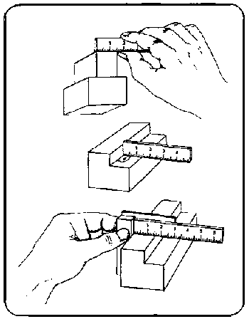
Figure 1.1
This transparency introduces some setting examples for recognizing the measuring values. The trainees have to put down the settings nos, two to five on a piece of paper and to check the results mutually by exchanging their papers.
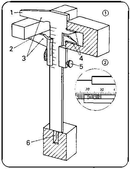
Figure 1.2
This reading test can also be performed without using this transparency. Therefore, the trainee has to read measuring values on the vernier caliper adjusted by the instructor. The vernier caliper has to be given a fixed measure, the fixing screw is to be tightened, and the device is to be passed on to the group of trainees. Every trainee puts down the measured value so that it might be checked afterwards. The following measuring tools should not be introduced before having a good command of handling the vernier caliper.
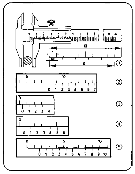
Figure 1.3
Transparency no. 1.4. may be used, in addition to the original tools, to introduce the dial gauge and external micrometer precision measuring tools. Exercises in reading the measuring values on the external micrometer may be done similarly to that with the vernier caliper according to transparency no. 1.5. Reading the values on the original tool should also be practised with setting examples.
Figure 1.4
Using the dial gauge may be demonstrated as follows:
The dial gauge rests on its support - a square-shaped workpiece with parallel bottom and top surfaces is to be put under the tracer pin which is slightly thrown in. The dial gauge scale is adjusted to “Zero” and the limit pointers are set at 10/100 mm on the right and left side of “Zero”.

Figure 1.5
Now the workpiece is to be moved to and fro under the tracer pin. The trainees can be shown that the indicator position beyond the limit pointers means that the range of tolerance has been exceeded.
The trainees have to learn what the term “tolerance” means. It is to be made clear to the trainees that an indicator position within the range of tolerance means that the quality is still “good”.
When describing the instruments for angular measurement, special emphasis is to be laid on handling the universal bevel protractor, as it guarantees a universal use.
Transparency no. 1.6. can be used for further clarification. After these instructions, it is recommended that the topic of faulty measurements should be discussed.
If possible, the main causes of such faults should be stated clearly:
- fault with the measuring instrument
- fault due to incorrect handling/use
- fault caused by environmental circumstances.
Figure 1.6
These instructions must be followed by hints for the prevention of such faulty measurements.
Testing tools
The order of testing tools in the list contained in the “Trainees’ Handbook of Lessons” is to be followed when explaining the use of these testing tools. First you should deal with the size gauges and make clear how they differ from form gauges. The definition of the terms contained in the “Trainees’ Handbook of Lessons” may be used to explain this difference.
Transparency no. 1.7. can serve to illustrate size gauges
Figure 1.7
- caliper, thickness gauge, hole gauge. Limit gauges can be seen on transparency no. 1.8.
Design and use of limit gauges need detailed information. Experience shows that it is not easy to learn how to handle these size gauges.
The trainees have to be given some information on the designation of limit gauges, which is derived from standards.
The trainees will learn that this designation indicates the maximum and minimum values of a standardized range of tolerance.
Figure 1.8
Comments on the use of limit gauges should be made during demonstrations of prepared test specimens. Thus, the trainees will le arn the distinction between the “go” end and the “not go” end of the various kinds of limit gauges.
It should be emphasized that the distinction between maximum and minimum values falls within the range of several hundredths of millimeters.
The trainees must realize that testing with these testing tools has to be carried out sensitively and non-violently.
When introducing the form gauges the instructor has to mention the light-gap method. The trainee will learn that the form of the gauge serves to make decisions on quality by comparison.
Figure 1.9
These gauges should be introduced in the following order:
- straightedges (steel straightedge, bevelled steel straightedge)
- squares (flat, try and bevelled edge squares)
- angle gauges
- radius gauges.
Transparency no. 1.9. can supplement this instruction.
The trainees must learn to evaluate the surface qualities of the object (workpiece) to be tested (checked) by using the light-gap method. It is recommended to illustrate the handling of these testing tools by using test specimens prepared in advance,
3.2. Exercises
The degree of difficulty in these exercises is to be increased step by step beginning with the easiest measuring and testing techniques and ending with the more complicated methods. Instruments for rough measuring should be dealt with first. To practise these measuring and testing techniques any objects available may be used as measuring specimens. The trainees must know the objectives of the exercises and that the results of measurements are subject to evaluation.
A short practice of handling the instruments is followed by exercises from the “Instruction Examples for Practical Vocational Training”.
Each of the individual exercises must be preceded by a brief “job-related instruction” in order to show the trainees where the measuring and testing methods have to be applied on the chosen objects.
The instructor can mention the major points of evaluation as well as the problems involved.
During these lessons of special instruction the trainees have to place the sequences of operations and working drawings with the tables to be completed contained in the “Instruction Examples” on their desks so that they can make notes therein.
All the trainees can carry out these exercises simultaneously, if the appropriate number of measuring and testing tools is available.
This being the case, the trainees can do the necessary exercises by themselves without being pushed by time limits. If the required number of tools cannot be provided, the waiting trainees should do other jobs in the workshop. It is a good practice to roughly prepare the initial materials for the subsequent exercises, e.g. selection of materials, sawing and shearing to rough nominal sizes, derusting, deburring etc. These activities need supervision!
3.3. Examples for recapitulation and tests
This section contains questions which are to consolidate and test the acquired skills and knowledge. All the exercises are provided with the necessary answers.
Questions which are also contained in the “Trainees’ Handbook of Lessons”, are marked with the letter “A”.
1. What is the purpose of measuring and testing?
(To check
dimensions, shape and surface finish of the workpiece during the manufacturing
process and to compare the data with the manufacturing drawing.)
2. Which testing methods do you know?
“A”
(Dimensional and non-dimensional testing methods.)
3. Which dimensional testing methods do you know?
(Testing
with measuring tools and testing with testing tools (gauges).)
4. What is the difference between measuring and
gauging?
“A” (Measuring serves to determine the exact sizes and
dimensions; gauging serves to find out deviations from dimensions and shapes
limited by a certain range of tolerance.)
5. Which measuring tools have a measuring accuracy of 1/10
millimeter?
“A” (Vernier caliper, depth gauge.)
6. Which measuring tools are used for precision measurements of
1/100 millimeter measuring accuracy?
“A” (External micrometer,
internal micrometer, depth micrometer, dial gauge.)
7. How do the individual types of instruments for angular
measurements differ?
“A” (Protractors with a range of 0 - 180
degrees for rough measurements; universal bevel protractors with a range of 0 -
360 degrees for precision measurements.)
8. Which measuring faults do you know?
(Faulty measuring
instrument, faulty handling, environmental influences.)
9. How can we avoid faulty measuring?
“A” (Repeated
measuring; use of faultless measuring instruments, proper handling of these
instruments; provision of a clean and well-lit workbench; measuring under the
same temperature conditions.)
10. What is the difference between measuring and testing
tools?
“A” (Measuring tools are provided with scales to read the
measuring value; testing tools do not have scales but only the designation of
the measure.)
11. What are size gauges?
(Instruments to determine sizes or
to check whether or not existing dimensions on an object are within the
stipulated limits.)
12. What are the special features of limit gauges compared to
simple size gauges?
“A” (They mostly comprise two size gauges for
the maximum and minimum size and are used with standardized and very close
ranges of tolerance.)
13. Which testing method is typical of using the cylindrical
limit plug gauge?
“A” (The “go” end must fit easily into
the true-to-size bore hole, the “not go” end must not.)
14. Which testing results do we obtain if we use limit screw
plug gauges?
“A” (Result: “go” or “not go”,
“go” does not say anything about external quality criteria.)
15. What are form gauges?
(Instruments to check flatness,
angles and accuracy of radius.)
16. Which testing method is typical of form
gauges?
“A” (Light-gap method - comparison of gauge and workpiece
through light incidence; light incidence must be uniform.)
17. How do squares and angle gauges differ?
“A”
(Squares are used to check the squareness of surfaces or edges/e.g. 90 degrees/;
angle gauges are designed for specific angles/e.g. 55 degrees/.)
18. Which are the main principles to be observed when employing
measuring and testing tools?
“A” (Keep measuring and testing tools
separate from cutting or hand tools, place them on soft pads, protect them them
shocks and
dropping.)
4. Application of the working techniques of “Measuring and Testing”
The sequence of exercises can focus on one subject according to the variant mentioned in section 3 or it may be divided into several stages.
The “Instruction Examples for Practical Vocational Training -Measuring and Testing” provide 8 exercises, the degree of difficulty of which increases gradually. These “Instruction Examples...” comprise a list of materials required (initial material, measuring and testing tools, accessories) as well as the sequence of operations and an illustrative working drawing.
Thus, the trainees avail of the necessary information to begin their exercise-related work.
The selection of exercises takes into consideration that in the majority of cases there are no manufactured pieces of work available and that the acquisition of measuring and testing techniques will be the first activities at the beginning of the course for such trainees. That is the reason why we have chosen objects which usually are available at the workbench or in the workshop.
4.1. Instruction examples
What follows is a short description of the individual training examples in order to give a survey of those objects at which the prior knowledge is to be verified.
Instruction Example 1.1.
Try Square
This testing tool shall serve as an object for simple rough and precise linear measurements by means of the steel rule, vernier caliper, depth gauge as well as for flatness testing by means of the bevelled steel straightedge.
Figure
Instruction Example 1.2.
Vee
A vee which is often used in a workshop shall be tested by using the steel rule, caliper, depth gauge and protractor (rough and precise measurements). Bevelled steel straightedge and bevelled edge square shall be used to test the flatness and squareness of faces.
Figure
Instruction Example 1.3.
Tap Wrench
This device shall serve as an object to practise linear and angular measurements of a higher degree of difficulty. The exact measuring point will be determined by rough and precision measurements.
Figure
Instruction Example 1.4.
Outside Calipers
This device shall serve to practise simple linear measurements by rough and precision measurements as well as radius measurements of external and internal radii and angles. The light-gap method roust be fully mastered.
Figure
Instruction Example 1.5.
Vernier Caliper
This device shall serve as an object to practise linear and angular measurements as well as radius determinations with a high degree of difficulty. External micrometers for precision measuring will add to the degree of difficulty.
Figure
Instruction Example 1.6.
Hexagonal-Head Bolt and Nut
In addition to simple linear and angle measurements, the thread is to be determined by using a limit gauge in order to check whether the external and internal threads are true to size.
Figure
Instruction Example 1.7.
Block Gauge
Some block gauges are arranged side by side so that differences can be measured by using a dial gauge. The skill of handling external micrometers is to be consolidated.

Figure
Instruction Example 1.8.
Plain Pins
The external micrometer is used to determine the dimensions of diameters; limit snap gauges shall serve to check true-to-size dimensions and tolerances according to standard values.

Figure
4.2. Criteria for practical training
It is recommended to determine some major points of observation and evaluation when the work is being carried out. The following criteria may serve as a guideline:
- Does the trainee handle the measuring and testing tools with care or negligence?- Does the trainee select the proper measuring tools?
- Are the surfaces to be measured and tested clean or does the trainee use the measuring/testing tool on surfaces which are not clean?
- Does the trainee read the correct measuring value or are there reading errors?
- Does the trainee employ the correct measuring force or does he cause damage by applying too much measuring force?
- Does the trainee use the “go” end and “not go” end of the limit gauges properly?
- Does the trainee put the form gauge on the surface properly or does he cant it?
- Does the trainee see the light gap and can be evaluate it?
5. Captions and legends of the “Measuring and Testing” transparencies series
|
Transparency No. 1.1.: |
Application of the Steel Rule | |
|
Transparency No. 1.2.: |
Design and Application of Vernier Caliper | |
| |
(1) Vernier caliper | |
| |
|
1 fixed jaw with measuring scale |
| | |
2 sliding jaw with vernier |
| | |
3 measuring jaw for external measurements |
| | |
4 measuring jaw for internal measurements |
| | |
5 clamping screw |
| |
|
6 depth gauge |
| |
(2) Vernier with a set measure of 20.8 mm | |
|
Transparency No. 1.3.: |
Vernier Caliper Setting Examples | |
| |
(1) Comparison of length of scale units and vernier units in millimeters | |
|
|
(2) Setting of 8 mm | |
| |
(3) Setting of 0.4 mm | |
| |
(4) Setting of 3.6 mm | |
| |
(5) Setting of 1.7 mm | |
|
Transparency No. 1.4.: |
Design and Application of Precision Measuring Tools |
|
| |
(1) Dial Gauge | |
| |
|
1 dial gauge |
| |
|
2 tolerance pointer |
| |
|
3 millimeter indicator |
| | |
4 0.01 millimeter indicator |
| | |
5 tracer pin |
| |
|
6 workpiece |
| |
|
7 support |
| |
(2) External Micrometer | |
| | |
1 tracer screw |
| |
|
2 case |
| | |
3 dial for 50/100 millimeter indication |
| | |
4 dial for whole and half millimeters |
| | |
5 clamping nut (locking) |
| | |
6 sliding tracer pin (measuring screw) |
| | |
7 fixed tracer pin (anvil) |
| | |
8 frame |
|
Transparency No. 1.5. |
Setting Examples at the External Micrometer | |
| |
(1) 8.27 mm setting | |
| |
(2) 13.01 mm setting | |
| |
(3) 8.77 mm setting | |
| |
(4) 0.59 mm setting | |
|
Transparency No. 1.6. |
Design and Application of Instruments for Angular Measurements | |
| |
(1) Protractor (120 degrees’ setting) | |
| |
(2) universal bevel protractor (150 degrees’ setting) |
|
| | |
1 scale with 4 x 90 degrees’ division |
| | |
2 vernier |
| | |
3 locking knob for scale |
| | |
4 locking knob for measuring jaw |
| | |
5 adjustable measuring jaw |
| | |
6 fixed measuring jaw (stop) |
|
Transparency No. 1.7. |
Application of Size Gauges | |
| |
(1) Testing of a stepped groove by block gauges | |
| |
(2) Testing of a narrow clearance by a thickness gauge |
|
| |
(3) Testing of a drill diameter by hole gauges | |
|
Transparency No. 1.8. |
Application of Limit Gauges | |
| |
(1) Testing of a true-to-size bore hole by a cylindrical limit plug gauge | |
|
|
(2) Limit screw plug gauge | |
| |
(3) Testing a bolt by the ring thread gauge | |
| |
(4) Testing a shaft diameter by the limit snap gauge | |
|
Transparency No. 1.9. |
Application of Form Gauges | |
| |
(1) Testing the flatness by the bevelled steel straightedge | |
| |
|
1 flat surface |
| |
|
2 hollow surface |
| |
|
3 crowned surface |
| |
(2) Testing of squareness (90) by the bevelled edge square |
|
| | |
1 exact angle |
| |
|
2 angle too small |
| |
|
3 angle too big |
List of Captions
Figures 1 through 9 according to transparencies 1.1. through
1.9.
Figures 10 through 17 according to instruction examples 1.1. through
1.8.
|
| ||||||||||||||||||||||||||||||||||||||||||||||||||||||||||||||||||||||||||||||||||||||||||||||||||||||||||||||||||
Manual Working of Material/Metal - Course: Manual working of metal. Methodical course-guide for instructors (Institut f�r Berufliche Entwicklung, 218 p.)
Marking and Punch Marking
1. Objectives and contents of practical vocational training in the working techniques of “Marking and Punch Marking”
By concluding their training, the trainees shall have a good command of the working techniques of “Marking and Punch Marking” Therefore, the following objectives are to be achieved:
Objectives
- Knowledge of the purpose and application of the marking and punch marking techniques.- Mastery of the various working techniques of marking and punch marking and capability of preparing the workpieces for good-quality working.
- Capability of selecting the proper scribing tools and their proper use.
- Capability of making decisions on quality independently.
The following contents have to be imparted to the trainees:
Contents
- Purpose of marking and punch marking
- Types and application of scribing tools and accessories
- Preparation of the surface of the workpiece.
2. Organizational preparation
In order to guarantee a trouble-free development of instruction, exercises and teaching it is necessary to prepare this training properly. The following steps have to be envisaged:
2.1. Preparation of instruction on labour safety
Prior to the exercises, a brief instruction on the proper use of marking and punch marking tools has to be given. This comprises hints for accident-free work. Emphasis is to be laid on:
- Points of scribers and dividers have to be protected by covering them with cork or plastic cases.- Never put scribing tools with projecting points in your pockets.
- Vernier height gauges have to be put down with their points turned away.
- Never use damaged or blunt scribing tools.
- As copper-sulphate solutions are poisonous, they have to be stored in marked and sealed vessels; avoid any contact with your skin when handling such solutions.
Familiarity with these hints is to be confirmed by the trainee’s signature in a control book.
2.2. Provision of teaching aids
- For demonstration purposes during instruction, a small surface plate should be installed on the workbench.
- The “Trainees’ Handbook of Lessons - Marking and Punch Marking’ is to be handed out to the trainees.
- When using the transparencies series of “Marking and Punch Marking” (transparencies 2.1. - 2.5.) check whether they are complete and whether the overhead projector is functional. (Check operating conditions at the site of use and make sure of the proper mains supply!)
- Surveys etc. which are to be written on the blackboard have to be completed prior to instruction.
- All the marking and punch marking tools mentioned in section 3 should be kept ready for illustration purposes.
2.3. Provision of working tools and materials
- Sufficient copies of the “Instruction Examples for Practical Vocational Training - Marking and Punch Marking” must be handed out to the trainees to provide them with the theoretical foundations of the exercises to be carried out.
- The initial materials required for the exercises are to be prepared and laid out in sufficient numbers according to the materials specified in the “Instruction Examples..,”.
- Each trainee is to be provided with a plane steel plate, which serves as a surface plate, and ideal lighting conditions.
- It must be checked that all workbenches are equipped with scribing tools and accessories appropriate to the exercises that are planned.
Recommended basic equipment:
- steel rule, steel straightedge, try square, bevelled edge square
- universal bevel protractor
- steel scriber, dividers, marking gauge, height gauge
- paint
- bastard files and smooth files (fist) 200 - 300 mm
- hammer; marking-out, centre and double-type punches
2.4. Time schedule
Time planning is recommended for the following training stages:
- introduction to the working techniques by way of instruction
- necessary demonstrations
- job-related instructions in preparing the exercises
- carrying out the exercises
- recapitulation and tests.
The necessary tine share depends on the respective training conditions. Most of the time is to be allocated to the exercises.
(...)
3. Recommendations for practical vocational training in the working techniques of ''Marking and Punch Marking''
(...)
Practical skills should be evaluated immediately after the handing in of the finished workpieces. Knowledge of theory should be constantly checked. However, it is recommended that a final test (item 1.3. or resp., 2.7.) should be written after concluding the exercises.
3.1. Introductory instruction
If possible, this instruction should be given in a classroom. Make sure that the trainees put down necessary supplementary hints or answers to questions in their “Trainees’ Handbook” of Lessons”.
Instruction can be carried out on the basis of the main points contained in the “Trainees’ Handbook of Lessons”.
Purpose of marking and punch marking
Instruction is to begin with the definition of terms and concepts This is followed by pointing out the significance of the scribing quality for the accuracy to size of the manufactured workpieces. The trainees should be encouraged to carry out the planned exercises with great care and accuracy.
Scribing tools and accessories
The introduction of scribing tools should follow the list contained in the “Trainees’ Handbook of Lessons”.
- steel scriber
- brass scriber
- soft pencil
- dividers (various types)
- scribing blocks (caliper gauge or marking gauge; height gauge)
- prick punches (marking-out, centre, double-point and stencil punches)
Demonstrating the original tools may be supported by using transparency no. 2.1.
The trainees must learn how and when to use the individual tools. They must be able to select the appropriate scribing tool necessary for completing the tasks and depending on the kind and surface of materials. The instruction in the field of accessories has to lay emphasis on the respective fields of application:
- surface plate
- angle plate
- large-size steel parallels
- vees
- stencils.
Figure 2.1
The instruction has to mention the measuring and testing tools the specific form of which makes it possible to support the motion of the scriber:
- steel rule
- try square
- T-square and centre square.
When dealing with the application of parallel scribing processes the instruction has to mention the mode of using scratch gauges.
Preparing the surface of the workpiece
The trainees should be shown that it is not always possible to produce clearly visible scribed lines on the various surfaces of the workpiece, if the scribing is performed directly on the surface. The trainee has to be instructed in the use of paints.
(...)-ng survey can be used to give instructions in em
(...)Lnts:
|
workpiece |
paint coating |
|
(...) big pore surfaces s and forgings |
coating with whiting prepared in water (a low percentage of linseed oil added) |
|
(...) caled steel parts |
coating with copper sulphate solution (CuSO4) -Caution: poisonous! |
|
Machined surfaces metals |
coating of shellac or scribing varnish |
(...) y is also contained in the “Trainees’ Handbook of
It with these problems you should mention the problem
(...) surfaces and lines. The emphasis is to be laid
on:
(...) ces and edges nes. o point out the significance of these datum
possibili-he accuracy of the scribed line.
(...)working techniques of
marking and punch marking
(...)ions of the working techniques should
include: with steel scriber and steel straightedge:
(...)is to be laid on the
proper position of the scriber.
(...)icy No. 2.2. can supplement this
demonstration, 3 with steel scriber and try square:
(...)3 to underline that
it is necessary to have one or two aces/edges in order to lay the try square
properly.
(...)icy No. 2.3. can be used as a supplement to instruc-the
use of centre squares and T-squares, djusting itua-e work-
(....)
Scribing with height gauge scriber
The difference in using the various height gauge scriber techniques has to be shown.
Transparency No. 2.5. can be used additionally to illustrate these techniques.
Punch marking after scribing
Instruction in handling the prick punches is to be supplemented by hints about how to make check punch marks according to recommended values.
The figures and formulas (also in the “Trainees’ Handbook of Lessons”) supplement the detailed instruction in the use of double-point punches for producing bore lines. Recommended values for check punch marks:
- spacing on straight sections 7 - 10 mm
- spacing on curved sections 3-4 mm.
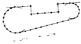
Figure
Correct spacings of check punch marks.
Formulas to calculate the boring lines:
D = y - 0.2 mm
x = D/2 + 0,5 mm
Conditions of producing a bore line
1 bore hole (D), 2 punch mark, 3 bore line, 4 scribed line - line of working, 5 width of double-point punch (y), 6 distance between bore line and scribed line (x)
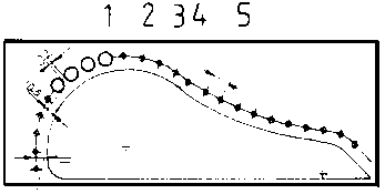
Figure
The trainees have to be shown that the compliance with these conditions of producing bore lines guarantees a minimum of additional treatment when finishing the workpiece.
3.2. Exercises
The degree of difficulty with these exercises is to be increased step by step - beginning with very simple scribing techniques. The trainees should start their work with simple and straight scribing operations using a steel scriber. They must know the exact objective of the exercise and that their results might be evaluated.
A short practice to consolidate the use of the tools is to be started with exercises from the “Instruction Examples for Practical Vocational Training”. However, it will be necessary to prepare each exercise by “job-related instructions”, in which the trainees are shown a finished workpiece to illustrate the objectives and main problems of this exercise. The instructor must have made such a workpiece himself in order to be familiar with all the problems which might arise in producing such a workpiece.
Thus the instructor can mention the major points of evaluation as well as the problems involved. During these lessons of special instruction the sequences of operations and working drawings must be placed on the tables so that the trainees can make notes therein.
All the trainees can carry out these exercises simultaneously, if the appropriate number of scribing tools is available. This being the case, the trainees can do each exercise by themselves without being pushed by time limits. If the required number of scribing tools cannot be provided, the group of trainees has to be subdivided according to the various categories of scribing applications:
group no. 1 - scribing with steel scribers
group no. 2 - scribing with scribing blocks
group no. 3 - scribing with dividers and punching with double-point punches
3.3. Examples for recapitulation and tests
This section comprises questions which are to consolidate and test the acquired skills and knowledge. Each question is accompanied by the respective answers. Questions which are also contained in the “Trainees’ Handbook of Lessons” are marked with the letter “A”.
1. What is the purpose of scribing?
(Transfer of form and
size of workpieces according to the dimensions on the manufacturing drawings to
the blanks in order to enable true-to-size working).
2. What is the purpose of punch marking?
(Punching of tapered
recesses for permanent marking of scribed lines, for supporting dividers points
and drills.)
3. What are the conditions a scribed line has to
fulfil?
“A” (Careful finish, accuracy, visibility during the entire
manufacturing process.)
4. Which effect must be produced by scribing
tools?
“A” (They have to produce clearly visible lines on the
workpiece).
5. What makes the difference in the use of steel scribers and
brass scribers?
“A” (Their results: steel scribers leave a fine
notch; brass scribers plot lines.)
6. When do we use dividers with adjustable points?
(If radii
are to be marked on stepped surfaces.)
7. What are the conditions a workpiece has to fulfil, if it is
to be marked with scribing blocks?
“A” (They must avail of flat
datum faces/edges to lay the scribing blocks.)
8. How do marking-out punch and centre punch
differ?
(Marking-out punch: angle of taper 40° for scribed lines;
centre-punch: angle of taper 60° for prick-punching of holes)
9. What are the conditions a workplace has to
fulfil?
“A” (Clean; well illuminated; spacious enough to put down
workpiece and accessories.)
10. What are the accessories to be used?
(Surface plate,
angle plate, large-size steel parallels, vees, stencils, some measuring and
testing tools.)
11. What makes the difference in the use of centre squares and
try squares?
“A” (Centre square: scribing of central points at
front sides of cylindrical workpieces; try square: scribing of straight lines on
flat surfaces of workpieces)
12. Why must certain surfaces of workpieces be coated with paint
prior to scribing?
“A” (Because the roughness of certain workpieces
does not allow a clearly visible scribed line.)
13. What paint is used as a coating for hard or scaled sheet
metal (scaled by hot rolling)?
(Copper sulphate solution.)
14. What kinds of datum are there for scribing?
“A”
(Datum surfaces, edges and lines.)
15. How do we guide the scriber at the steel straightedge or try
square?
“A” (Drawing the scriber point directly along the edge of
the straightedge or square with the scriber slightly inclined towards the body.)
16. What is a necessary intermediate step in scribing with
dividers?
“A” (Making of check arcs to check the set radius.)
17. What are the accessories necessary for scribing with height
gauge scribers?
“A” (Surface plate, angle plate, parallel piece.)
18. What are the conditions under which a parallel piece has to
be used as workpiece support when employing height gauge scribers for
scribing?
(If the height gauge scriber does not allow a zero-position of the
scriber at the level of the surface plate.)
19. What makes punch marking of scribed lines
necessary?
“A” (This must be done, if the following treatment will
blur these lines or if the visibility during manufacture is restricted or if the
surface conditions of the workpiece deteriorate the visibility.)
20. What spacing must be used for check punch
marks?
(Straight sections: 7-10 mm) curved sections: 3 - 4 mm)
21. What size is of prime importance for bore line
marks?
“A” (Width of double-point punch/y/of the double-point punch
to be used.)
22. How is punching done with double-point punches?
(One
point of the double-point punch has to be placed in the previous punch mark; the
punch has to be set upright; punching can be performed now.)
23. What are the dangers associated with the use of scribing
tools?
(Danger of injuries by the sharp
points.)
4. Application of the working techniques of “Marking and Punch Marking”
The sequence of exercises can focus on one topic each according to the variant mentioned in section 3 or it may be divided into several stages.
The ‘‘Instruction Examples for Practical Vocational Training” provide 7 exercises whose degree of difficulty increases gradually.
These “Instruction Examples...” comprise a list of required materials (initial material, hand tools, measuring and testing tools, accessories) as well as the sequence of operations for carrying out the exercise and an illustrative working drawing. Thus, the trainees avail of the necessary information to do their exercises in an objective-related way.
The selection of exercises takes into consideration that such workpieces are scribed which will be used in the further stages of treatment with other working techniques, i. e. that they serve a certain purpose.
That is the reason why these workpieces should be marked with the trainee’s name in order to finish them at a later stage.
4.1. Instruction examples
To give a survey of the workpieces on which the prior knowledge shall be verified, the individual training examples are described in brief here.
Instruction Example 2.1.
Door Lock Panel
Scribing of straight and parallel lines on steel plates by using the steel rule, steel straightedge and steel scriber starting from datum edges.
The dimensions of the break-throughs can be adapted to local conditions so that this component can be screwed on a door frame after being finished by sawing, drilling and filing.
Figure
Instruction Example 2.2.
Holding Clamp
Scribing of straight and angular lines on steel sheet using a try square and protractor as well as a datum edge and a datum line.
Together with the instruction examples 5.1., 5.2. and 5.5. this will constitute a set of clamping tools for an upright drilling machine.
Figure
Instruction Example 2.3.
Drill Stand
Scribing of straight and parallel lines using scribing blocks on rolled steel channels based on datum edges.
After having finished this part it can be used as support for drills. Instruction example 7.4. describes how to finish this component.
Figure
Instruction Example 2.4.
Angle Gauge
The universal bevel protractor is used for scribing angular lines on steel sheet based on datum edges. After having been finished, this instrument can serve as a testing tool in the field of sharpening tools, as this gauge contains the most important angle sizes.
Figure
Instruction Example 2.5.
Bow for C Clamp
Scribing of lines on steel sheet using height gauge scriber and dividers based on datum edges and a datum line.
Another major point of work refers to marking a bore line according to fixed dimensions. After being completed, this part will be a component of a C clamp which can be used in the workshop. (This comprises also the parts mentioned in the instruction examples 7.6., 8.2. and 9.5.)
Figure
Instruction Example 2.6.
Open-end Wrench 19/24
Scribing of symmetrical, curved and straight lines on steel sheet using a datum line as the central line.
Additionally, a bore line will be scribed and punch marked. After finishing this test workpiece it can be used in the workshop to fasten/loosen hexagonal-head bolts and M12 or, resp. M16 nuts.
Figure
Instruction Example 2.7.
Base Plate
On a circular steel plate the contour and markings for boreholes will be scribed using a steel rule, dividers and centre square. Then a bore line is to be scribed. When this workpiece has been finished, various devices (e.g. workbench lamp) can be mounted with this base plate on a workbench.
Figure
4.2. Criteria for practical training
It is recommended to determine some major points of observation and evaluation when the work is being carried out. The following criteria may serve as a guideline:
- Does the trainee use the scribing tools so that injuries will be avoided?
- Are the surfaces of the workpiece coated with the appropriate paints, if necessary?
- Are the datum lines/edges up to the standards?
- Is the position of the steel scriber correct?
- Are the transitions from straight lines to curved ones clean and without steps?
- Does the trainee draw the necessary lines only or does he produce a maze of lines?
- Are the scribed lines clear and a single line only or are there any double lines?
- Are the supporting points for the dividers sufficiently prepunched?
- Are the scribers of the scribing block exactly adjusted?
- Are the spacings of the check punch marks correct?
- Are the check punch marks exactly on the scribed line or not?
- Are the bore lines correctly scribed and punched according to the given conditions?
5. Captions and legends to the “Marking and Punch Marking'' transparencies series
|
Transparency No. 2.1. |
Scribing Tools | |
| |
(1) steel scriber | |
| |
(2) brass scriber | |
| |
(3) pencil (soft) | |
| |
(4) dividers | |
| |
(5) prick-punches | |
| |
|
1 - marking-out punch |
| | |
2 - centre punch (6) double-point punch (9) height gauge scriber with scale |
|
Transparency No. 2.2. |
Technique of Scribing and Prick-Punching | |
| |
(1) locating of scriber | |
| |
(2) placing the punch and upright position for punching. |
|
|
Transparency No. 2.3. |
Scribing with Steel Squares | |
| |
(1) scribing with try square | |
| |
(2) scribing of shaft centre with centre square | |
| |
(3) scribing of shaft centre with T-square | |
| |
(4) scribing of central lines with T-square | |
|
Transparency No. 2.4. |
Scribing with Dividers | |
| |
(1) scribing with toolmakers’ dividers(using an inset, because the supporting point is located outside the workpiece) | |
| |
(2) scribing with beam trammel | |
|
Transparency No. 2.5. |
Scribing with Scribing Blocks | |
| |
(1) caliper gauge (2) marking gauge (3) height gauge scriber | |
|
| ||||||||||||||||||||||||||||||||||||||||||||||||||||||||||||||||||||||||||||||||||||||||||||||||||||||||||||||||||
Manual Working of Material/Metal - Course: Manual working of metal. Methodical course-guide for instructors (Institut f�r Berufliche Entwicklung, 218 p.)
Hammering and Marking
1. Objectives and contents of practical vocational training in the working techniques of “Hammering and Marking”
By concluding their training the trainees shall have a good command of the working techniques of “Hammering and Marking”. Therefore, the following objectives are to be achieved:
Objectives
- Knowledge of the purpose and ranges of application of the hammering and marking techniques.
- Mastery of the various working techniques of hammering and marking.
- Capability of selecting the proper tools and accessories and of their proper use.
- Capability of evaluating the quality of their work.
The following contents have to be imparted to the trainees:
Contents
- Purpose of hammering and marking
- Tools and accessories
- Effect and working techniques of hammering
- Working techniques of marking.
2. Organizational preparation
To guarantee a trouble-free development of instruction, exercises and practical work it is necessary to prepare this training appropriately. The following steps have to be taken:
2.1. Preparation of instructions on labour safety
Prior to the exercises, a brief instruction in the proper use of working tools and in guaranteeing an accident-free work has to be given. The main emphasis is to be laid on:
Use of flawless hammers with well-fixed handles only.
Selection of the proper (hard and inflexible) support for hammering.
Use of burr-free punches.
Precautions for preventing fire damage in case of annealing the steel sheets.
Familiarity with these hints is to be confirmed by the trainees’ signatures in a control book.
2.2. Provision of teaching aids
For demonstration purposes during instruction, a vice and appropriate hammering supports have to be installed at the place.
The “Trainees’ Handbook of Lessons - Hammering and Marking” has to be handed out to the trainees, when using the transparencies series of “Hammering and Marking”, check whether it is complete (transparencies 3.1. - 3.4.) and whether the overhead projector is functional. (Check the operating conditions at the place of use and make sure of the proper mains supply!)
Surveys which are to be written on the blackboard have to be completed prior to instruction.
All the tools and accessories mentioned in section 3 (for hammering and marking operations) should be kept ready for illustration purposes.
2.3. Provision of working tools and materials
The “Instruction Examples for Practical Vocational Training
- Hammering and Marking” must be handed out to the trainees in sufficient copies to provide them with the theoretical foundations for the exercises to be performed.
The initial materials necessary for the exercises are to be prepared and laid out in sufficient numbers according to the specifications of the “Instruction Examples...”.
Each trainee is to be provided with a workbench that is equipped with a flat hammering support and a firmly installed vice (check whether it has the appropriate working height).
It must be checked that all workbenches are fully equipped with tools and accessories specified for the planned exercises. Recommended basic equipment:
- steel rule, vernier caliper, protractor
- steel scriber, centre punch, dividers
- hand hacksaw or hand-lever shear
- bastard and smooth files 200 mm (flat)
- locksmith’s hammer (engineers’ hammer) chasing hammer, curving hammer, wooden hammer
- sledge, bordering tool, marking punch (numbers and letters)
- surface plate or anvil, clamping devices.
2.4. Time schedule
Time planning is recommended for the following training stages:
- introduction to the working techniques by way of instruction
- necessary demonstrations
- job-related instructions for carrying out the exercises
- carrying out the exercises, recapitulation and tests.
The necessary time share depends on the respective training conditions. Most of the time is to be allocated to the exercises
3. Recommendations for practical training in the working techniques of “Hammering and Marking”
The following paragraphs comprise proposals on conducting trainee instruction, carrying out demonstrations of working techniques as well as exercises and tests. We recommend two course variants:
Variant No. 1.
This variant should be chosen for trainees with generally good achievements and receptiveness.
1.1. Introductory instruction to the whole subject, accompanied by demonstrations specified in the “Trainees’ Handbook of Lessons”1.2. Exercises in hammering and marking as well as subsequent evaluation as specified in the “Instruction Examples 3.1. -3.7.”
1.3. Test of theory knowledge based on the contents of “Examples for Recapitulation and Tests”.
Variant No. 2.
This variant should be chosen for trainees with little previous knowledge or poor achievements.
2.1. Introductory instruction for the subjects of “Lengthening (elongating) and curving”, accompanied by demonstrations specified in the “Trainees’ Handbook of Lessons”.2.2. Exercises in lengthening and curving as specified in the “Instruction Examples 3.1. - 3.4.” and subsequent evaluation.
2.3. Supplementary instruction in the subject of “Chasing and flanging (bordering)” as specified in the “Trainees’ Handbook of Lessons”.
2.4. Exercises in chasing and flanging as well as evaluation, as specified in the “Instruction Example 3.5.”.
2.5. Supplementary instruction in the subject of “Marking” as specified in the “Trainees’ Handbook of Lessons”.
2.6. Exercises in marking, with subsequent evaluation as specified in the “Instruction Examples 3.6. and 3.7.”.
2.7. Final test of theory knowledge as specified in the “Examples for Recapitulation and Tests”.
The evaluation of practical skills should be done immediately after handing over the finished workpiece to the instructor. Knowledge of theory can be permanently checked, but it is advisable to have a final test paper (item 1.3. or, resp., 2.7.) after concluding the exercise.
3.1. Introductory instruction
If possible, this instruction should be given in a classroom.
Make sure that the trainees put down necessary, supplementary hints or answers to questions in their “Trainees’ Handbook of Lessons”.
Instruction may be conducted on the basis of the main points contained in the “Trainees’ Handbook of Lessons”.
The main subjects of “purpose of hammering and marking” as well as “tools and accessories for hammering” should be accompanied by an intensive employment of all those teaching aids available.
Purpose of hammering and marking
To demonstrate the purpose of these working techniques, it is advisable to show such workpieces which had been formed, straightened or, resp., marked by figures and letters. The instructor has to point out that this is mainly used in single-piece production. A summary can be given by using the “Trainees’ Handbook of Lessons” as a guideline.
Tools and accessories
Transparency No. 3.1. can supplement the demonstration of original tools and accessories.
When describing the individual tools and accessories, their intended purpose has to be pointed out.
The following tools have to be shown and introduced:
- locksmith’s hammers (hand hammer, riveting hammer, bench hammer)- hammers for sheet metal working (chasing, curving, finishing and planishing (or smoothing) hammers as well as wooden, rubber and aluminium hammers).
Following this instruction, the trainees should be in a position to describe the intended purpose of these hammers and to use their correct designations (using size and shape of hammers as distinctive marks).
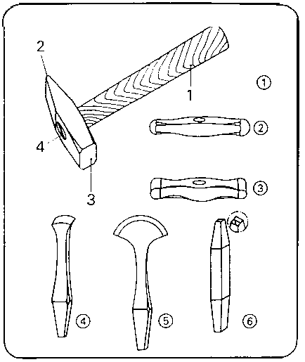
Figure 3.1
This is followed by remarks on hammering supports:
- surface plate
- blacksmith’s anvil
- special supports for sheet metal working (anvil tool, sledge, blacksmiths’ hardy and bordering tool).
The intended purpose of using these supports is to be made quite clear.
The following marking tools should be included in the demonstrations:
- sets of letters (in an alphabetical order)
- sets of numbers
- punches with special numbers or words.
If not all of these tools and accessories are available as originals, the illustrations contained in the “Trainees’ Handbook of Lessons” may be employed.
Effect of Hammering
The effects of hammering should be demonstrated by some examples A narrow strip of sheet metal should be worked with the face of a hammer and with the pane of a hammer. Thus, the trainees will learn that the processes of lengthening and upsetting will be influenced by the form of the hitting area of the tool as well as by the form of the hammering support. The trainee has to learn the technique of hardening the material by cold working, i.e. by many blows of the hammer. Annealing and the various types of cooling down depending on the kind of material should be mentioned in these instructions. The trainees should be shown how to position the hammer when performing the blows. It is recommended that each trainee does some blows with a hammer, so that mistakes can be corrected immediately. Following this, the trainees should answer the questions contained in the “Trainees’ Handbook of Lessons” in writing.
Working techniques of hammering
The various working techniques should be taught in the following order:
Lengthening
The trainees can be shown the hammering technique of using the face or pane of a hammer once again.
The trainees will understand that blows with the pane will lengthen the material, whereas the face will lengthen and widen the material.
Transparency No. 3.2. can illustrate this process.
Curving
The trainees have to be shown the use of the pane of a locksmith’s hammer or the faces of a curving hammer.
When demonstrating this working technique, emphasis is to be laid on evenly distributed hammer blows - the strip of sheet metal must show an arch-like curvature.
Transparency No. 3.3. will help to make this and the following working techniques clear.
Chasing
Two possible variants have to be demonstrated.
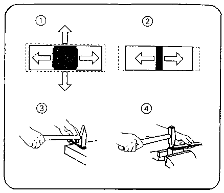
Figure 3.2
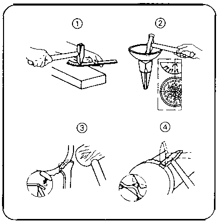
Figure 3.3
Variant No. 1
When using the face of a chasing hammer on a flat support, the instructor has to show that the hammer blows begin at the centre of the workpiece and then follow a spiral-like pattern to the outside of the workpiece.
Variant No. 2
When chasing with a rounded wooden hammer or chasing hammer on a hollow support, the instructor has to show that the hammer blows begin at the outside and advance to the centre in a spiral-like pattern.
This is followed by referring to the process of hardening by cold working again. The trainees have to learn that cracks will occur in the sheet metal, if this fact is neglected. Later on the trainees are shown the appropriate forms of annealing and cooling down in a workshop.
Flanging
The various techniques of outside and inside flanging can be explained in combination with the figures in the “Trainees’ Handbook of Lessons”.
It should be emphasised that this working technique is divided into two stages: rough-flanging and finish-flanging.
The use of various types of hammers (locksmith’s hammer, bevelled wooden hammer, chasing hammer, curving hammer) has to be mentioned at the appropriate place.
Working technique of marking
When imparting the knowledge of placing and blowing the marking punch to the trainees, they have to be informed on the necessary preparation by appropriately scribed lines. The interdependence of height of letters and space between the lines should be demonstrated briefly. This demonstration can refer to the following table and its recommended values:
|
space between the lines |
height of figures or letters |
|
3 |
2.5 |
|
5 |
4 |
|
8 |
6 |
|
10 |
8 |
|
12 |
10 |
A small piece of sheet metal may serve to demonstrate the working technique of scribing using a marking gauge. The following hints should be included in the instruction on marking punches:
- The head of the punch must be burr-free.
- The engraving of a figure or letter must be perfect.
- The marking punch must not be crooked.
The trainees have to learn that marking operations require a high degree of concentration. This makes it necessary for the order of figures and letters during the marking operation to be permanently monitored.
Transparency No. 3.4. can be used to further illustrate this fact.
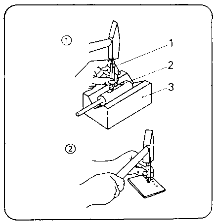
Figure
3.4
3.2. Exercises
If it was not possible to include demonstrations in the instruction, this must be done prior to the start of the exercises. If the trainees avail of only little practical skills, they should perform preliminary exercises on any small-size workpieces:
- minor exercises in lengthening sheet metal strips
- curving of a simple arch
- marking a combination of figures.
However, it is also possible to begin with the first exercise specified in the “Instruction Examples for Practical Training”, at once.
However, it will be necessary, to prepare each exercise by a brief “job-related instruction”, in which the trainees are shown a finished workpiece in order to make the purpose and intention of the exercises quite clear.
The instructor must have finished such a workpiece by himself, so that he knows the problems involved in producing such a workpiece.
This makes it possible to identify the main points in evaluating the trainees’ work and to inform them about difficult areas on the workpiece. During this special instruction, the sequences of operations and working drawings should be on the desks so that the trainees can make notes therein. All the trainees can carry out the exercises simultaneously, if the appropriate number of working tools is available. If this is not possible, the trainees will be divided into groups according to the various categories of work and number of the tools available. Trainees who cannot start with hammering and marking operations should perform some other activities in the workshop: selection and preparation of initial materials, checking and minor repair work on working tools under the supervision of the instructor. It is also possible to carry out exercises which consolidate the skills and knowledge of previously learned working techniques.
3.3. Examples for recapitulation and tests
This section comprises questions which should help to consolidate and test the acquired knowledge and skills. Each question is provided with the respective answer. Questions which are also contained in the “Trainees’ Handbook of Lessons” are marked with the letter “A”.
1. What is the purpose of hammering?
(Working of sheet and
sectional metal by carefully directed blows of a hammer for forming,
straightening, strengthening or hardening the workpieces.)
2. What is the purpose of marking?
(Punching of figures and
letters into the surfaces of workpieces in order to distinguish them from each
other or to indicate the order of assembling or to mark necessary manufacturing
data in a long-lasting manner.)
3. How do the design types of locksmith’s hammer and
hammers for sheet metal working differ?
“A” (Locksmith’s
hammers differ from one another by their weight and size, but their heads show a
uniform shape. Hammers for sheet metal working have, apart from differing
weights, a differing form of faces and they have no panes.)
4. What are the required properties of hammering
supports?
“A” (Rigid, inflexible, possibly hardened - smooth
surface.)
5. Which hammering supports are meeting the general requirements
of hammering?
“A” (Surface plate, blacksmith’s anvil.)
6. Which hammering supports meet the special requirements of
sheet metal working?
(Anvil tool, sledge, blacksmiths’ hardy and
bordering tool,)
7. What types of marking punches are generally
used?
“A” (Letter punches and figure punches.)
8. What is the typical effect of hammering?
“A”
(The impact of the hitting hammer head upsets the material which has to give way
laterally. The hammering support prevents a displacement into the direction of
the blow.)
9. What property must materials have that shall be
hammered?
“A” (They must be ductile.)
10. What is the effect of many hammer blows on a single spot of
a workpiece?
“A” (The material consolidates and gets hard and
brittle.)
11. How can this effect be reduced or
eliminated?
“A” (Annealing or cooling down.)
12. Which difference do we have to consider in working steel
sheets and in working copper sheets with this technique?
(Steel sheets have
to be cooled down slowly, copper sheets have to be cooled down fast.)
13. What makes the difference in lengthening and curving of a
metal strip?
“A” (Lengthening will elongate the metal strip in a
straight line or widen it at the same time; curving will lengthen the metal
strip unilaterally and bend it arch-like on the plane.)
14. How must the blows be directed when lengthening and
curving?
“A” (Short, successive blows from front to rear or from
rear to front.)
15. Which variants of blows are possible in chasing sheet
metal?
(Variant 1: The blows of the hammer will be performed spirally on a
flat hammering support - beginning inside and ending outside.
Variant 2: The
blows of the hammer will be performed spirally on a hollow hammering support -
beginning outside and ending inside.)
16. What are the working steps of flanging borders of sheet
metal?
“A” (Rough-flanging - bending down of the border of the
metal sheet finish-flanging - bulging-in of the wrinkles and smoothing of the
border.)
17. Which hammering supports should be used when flanging lids
or covering caps of containers?
(The container to be covered should serve as
a hammering support.)
18. How must we scribe the lines necessary for marking
combinations of figures or letters?
(With pencil or brass scriber - the
spacing must slightly exceed the height of the figures or letters.)
19. What must be done first, if the marking has to be performed
on rough or curved surfaces?
(The sections of the surfaces to be marked have
to be smoothed or levelled
first.)
4. Application of the working techniques of “Hammering and Marking”
The sequence of exercises can focus on one topic each according to the variant mentioned in section 3 or it may be divided into several stages.
The “Instruction Examples for Practical Vocational Training -Hammering and Marking” provide 7 exercises whose degree of difficulty increases gradually.
These “Instruction Examples...” comprise a list of required materials (initial material, hand tools, measuring and testing tools, accessories), as well as the sequence of operations for producing the workpiece. An illustrative working drawing is also contained in these “Instruction Examples...”. Thus, the trainees avail of the required information to do their exercises in an objective-related way. If the progress of work during the exercises shows that the achieved quality standards of the workpieces is not sufficient, the trainees must carry out comprehensive preliminary exercises. In this case it is possible to use any appropriate waste components. If the skill has been practised sufficiently, the workpiece mentioned in the “Instruction Examples...” can be manufactured. Please, take the following hint into consideration:
|
From the very beginning (i. e. cutting to size) until finishing the workpiece, the trainee has to do all the associated work by himself. This is the only way to guarantee a just evaluation of his achievement. |
If the “Instruction Examples...” offered in this material should not be used for exercise purposes, it will be possible to work on other workpieces. However, you have to see to it that all the previous working techniques will be practised with that exercise.
4.1. Instruction examples
To give a survey of the workpieces on which the previous knowledge shall be practised, the individual instruction examples are described in brief here:
Instruction Example 3.1.
Nameplate
A narrow strip of sheet steel is lengthened with the pane of a hammer so that it becomes 10 mm longer.
Action of the surface is smoothed with a hammer and sledge and then the trainee’s name is marked on it.
This plate may be fixed to the finished workpieces so that it is easier to identify them.
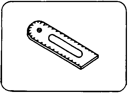
Figure
Instruction Example 3.2.
Number Plate for Locker
A narrow strip of sheet steel is curved with the pane of a hammer according to specified dimensions. After smoothing a section of the surface and marking it with a figure it can be used as a numberplate for tool cabinets and wardrobes.

Figure
Instruction Example 3.3.
Screw driver
The face of a hammer is used to flatten round bar steel so that a screw driver blade and a handle extension will be produced. This workpiece can be finished by filing or grinding it according to Instruction Example 12.3.
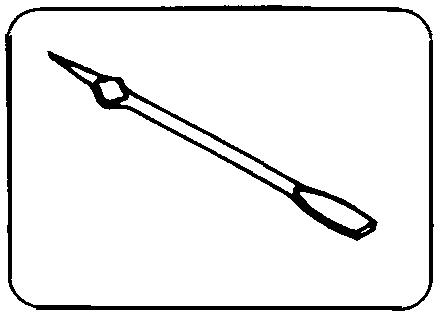
Figure
Instruction Example 3.4.
Copper Bit of a Soldering Iron
Round bar copper material is flattened with the face of the hammer and then work-hardened. After its completion this workpiece can be used in the workshop.
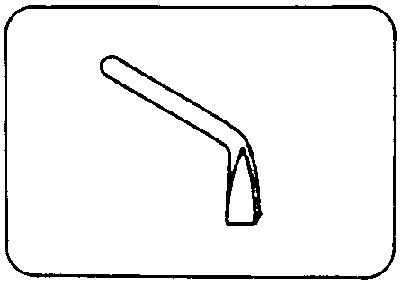
Figure
Instruction Example 3.5.
Bowl with Cover
Placed upon a hollow hammering support (steel tube), thin copper sheets are chased to form a bowl; a second sheet will be flanged so that it forms a cover matching the bowl.
Figure
Instruction Example 3.6.
Table to Determine Tapping Drill Holes and Bore Depths
A table is punch-marked into a small-size steel sheet. When applying the working technique of “Thread Cutting” it will serve as a means to determine the required values.
Such a table is very handy and can be added to the personal tools of the trainee.
Figure
Instruction Example 3.7.
Table to Determine Widths across Flats and Widths across Corners of Hexagon-Head Screws and Nuts
A table will be punch-marked into a small-size steel sheet. In the assembly of screwed connections these values are required. They serve to select the proper open-ended spanners for the hexagon-head screws and nuts. This table is handy and can be added to the personal tools of the trainee.
Figure
4.2. Criteria for practical training
It is recommended to determine some major points of observation and evaluation when the work is being carried out. The following criteria may serve as a guideline:
Lengthening
Is the sequence of blows of the hammer uniform and narrowly spaced from one side to the other or does the trainee strike here and there at random?
Does the metal sheet stay straight during lengthening or does it curve?
Curving
Is the curvature of the sheet even or are there waves?
Chasing
Do the blows of the hammer comply with the respective variant (according to the hammering support)? Does the trainee take cold-hardening into consideration and are there the proper intervals for cooling down the sheet?
Are there any cracks resulting from chasing? Is it an even curvature or are there any buckles?
Flanging
Does the trainee observe the two working stages of rough-flanging and finish-flanging?
Does the trainee employ the appropriate types of hammers?
Is it an even flanging or are there any waves and irregularities?
Marking
Are the lines scribed with proper spacings?
Is the position of figures or letters even and upright?
Is there an even depth of punching?
Can the figures or letters be clearly identified or are there any double punchings?
5. Captions and legends of the “Hammering and Marking” transparency series
|
Transparency No. 3.1. |
Selected Tools for Hammering and Marking | |
| |
(1) Locksmith’s hammer | |
| | |
1 wooden handle |
| |
|
2 pane |
| | |
3 face |
| | |
4 wedge |
| |
(2) chasing hammer | |
| |
(3) curving hammer | |
| |
(4) bordering tool (flanging tool) | |
| |
(5) blacksmiths’ hardy | |
| |
(6) marking punch | |
|
Transparency No. 3.2. |
Flattening (widening) and Lengthening with Locksmith’s Hammers | |
|
|
(1) Effect of hammer face | |
| |
(2) effect of hammer pane | |
| |
(3) flattening and lengthening with hammer face | |
| |
(4) lengthening with hammer pane | |
|
Transparency No. 3.3. |
Curving, Chasing, Flanging | |
| |
(1) curving with pane of locksmith’s hammer | |
| |
(2) chasing of a bowl with chasing hammer | |
| |
(3) flanging of metal sheet border with blacksmiths’ hardy and wooden hammer | |
| |
(4) bulging-in of wrinkles with locksmith’s hammer |
|
|
Transparency No. 3.4. |
Marking with marking punches | |
| |
(1) marking on curved surfaces | |
| | |
1 marking punch |
| |
|
2 filed area |
| |
|
3 vee support |
| |
(2) marking of combinations of figures -at right angles to the line of sight | |
|
| ||||||||||||||||||||||||||||||||||||||||||||||||||||||||||||||||||||||||||||||||||||||||||||||||||||||||||||||||||
Manual Working of Material/Metal - Course: Manual working of metal. Methodical course-guide for instructors (Institut f�r Berufliche Entwicklung, 218 p.)
Manual Sawing
1. Objectives and contents of practical vocational training in the working technique of “Manual Sawing”
By concluding their training the trainees shall have a good command of the working technique of “Manual Sawing”. Therefore, the following objectives are to be achieved:
Objectives
- Knowledge of the purpose and application of manual sawing.
- Mastery in handling the saw and capability of carrying out true-to-size sawing cuts of any kind.
- Capability of selecting the proper tools and accessories and their proper use.
- Capability of evaluating the quality of their own work.
The following contents have to be imparted to the trainees:
Contents
- Purpose of sawing
- Tools and accessories
- Effects of sawing and handling of saws
2. Organizational preparation
To guarantee a trouble-free development of instructions, exercises and practical work it is necessary to prepare this training properly.
The following steps have to be taken:
2.1. Preparation of instructions on labour safety
Prior to the exercises a brief instruction on the proper use of tools and materials has to be given. This comprises hints for accident-free work.
The main emphasis is to be laid on:
- Hand hacksaws with crackless handles must be used only
- Fixing components must not protrude at the side of the clamp dog!
- The guide hand must not work in the range above the vice!
Familiarity with these hints is to be confirmed by the trainee’s signature in a control book.
2.2. Provision of teaching aids
For demonstration purposes during instruction, a vice has to be installed at the place.
The “Trainees’ Handbook of Lessons - Manual Sawing” is to be handed out to the trainees.
When using the transparencies series of “Manual Sawing”, check whether they are complete (transparencies nos. 4.1. - 4.3.) and whether the overhead projector is functional. (Check the operating conditions at the place of use and make sure of the proper mains supply!)
Surveys which are to be written on the blackboard have to be completed prior to instruction.
All the tools and accessories mentioned in section 3 (for sawing purposes) should be kept ready for demonstration.
2.3. Provision of working tools and materials
The “Instruction Examples for Practical Vocational Training -Manual Sawing” must be handed out to the trainees in sufficient copies to provide them with the theoretical foundations for the exercises to be performed.
The initial materials necessary for the exercises have to be laid out and prepared in sufficient numbers of copies according to the specifications mentioned in the “Instruction Examples...”.
Each trainee is to be provided with a workbench with a stationary vice (check the proper working height of the vice).
The trainees’ workbenches have to be fully equipped with tools and accessories according to the exercises planned. Do not forget to check this! Recommended basic equipment:
- steel rule, try square, protractor
- steel scriber, prick-punch, dividers
- locksmith’s hammer
- hand hacksaw with various types of saw blades
- bastard and smooth files - 200 mm and 250 mm (flat and half round)
- vee clamps.
2.4. Time schedule
Time planning is recommended for the following training stages:
- introduction to the working technique in the form of instructions
- necessary demonstrations
- job-related instructions in performing the exercises
- performing the exercises
- recapitulation and tests.
The necessary time share depends on the respective training conditions. Most of the time is to be allocated to the exercises
3. Recommendations for practical vocational training in the working technique of “Manual Sawing”
The following paragraphs comprise proposals on conducting trainee instruction, the demonstration of the working techniques as well as exercises and tests. We recommend the following way of conducting the course:
Introductory instruction with demonstrations from the “Trainees’ Handbook of Lessons”.
Exercises in sawing from “Instruction Examples 4.1. - 4.6.” and subsequent evaluation.
Final test of theory knowledge based on the contents of the
“Examples for Recapitulation and Tests”.
The exercise associated with “Instruction Example 4.7.” can follow later as a complex work, because it is necessary to acquire other working techniques first.
Practical skills should be tested immediately after handing over the finished workpiece. Knowledge of theory should be constantly checked. However, it is recommended that a final test paper should be written after the conclusion of the exercises.
3.1. Introductory instruction
If possible, this instruction should be given in a classroom. Make sure that the trainees put down necessary supplementary hints or answers to questions in their ‘‘Trainees’ Handbook of Lessons”.
Instruction can be carried out on the basis of the main points contained in the “Trainees’ Handbook of Lessons”. The main subjects of “Purpose of Sawing” and “Tools and Accessories for Sawing” are to be taught with the employment of all the teaching aids available.
Purpose of sawing
This subject should be illustrated by presenting workpieces which were cut by sawing or which show kerfs. The trainees should recognize the single-piece nature of this work.
Tools and accessories
Transparencies nos. 4.1. and 4.2. can support the demonstration of original tools and accessories. The design of a hand hacksaw and the fixing of the saw blade is to be explained.
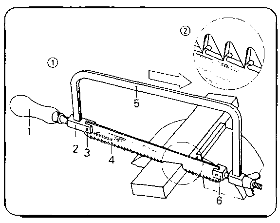
Figure 4.1
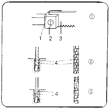
Figure 4.2
The following surveys should support the introduction to saw blades:
Saw blades for different material hardness
|
Hardness of material |
chip formation |
angle of clearance |
wedge angle |
rake angle |
|
hard |
shaving - |
|
|
|
|
|
small amount of chips |
40° |
50° |
0° |
|
normal |
cutting - |
|
|
|
|
|
small amount of chips |
20° |
65° |
5° |
|
soft |
cutting - |
|
|
|
|
|
large amount of chips |
30° |
50° |
10° |
Saw blades for different cross sections of workpieces and degrees of material hardness
|
Type of saw blade |
cross section of workpiece |
material hardness |
tooth pitch (number of teeth on 25 mm) |
|
coarse |
- solid sections (round, square and hexagonal steels) |
soft steel, non-ferrous metals |
14 |
|
normal |
- normal sections (angles, sectional steel) - thick sheet metal |
steel of normal hardness, harder light metals |
22 |
|
fine |
- light-steel sections - thin sheet metal |
harder steel, cast iron |
32 |
The instructor has to stress the importance of the free cutting action of saw blades.
For the purpose of demonstration one trainee is to be given the task to perform a sawing cut on any workpiece using a saw blade with free cutting action first, and then a saw blade without (or with poor) free cutting action. The trainees have to register the required times for sawing and to draw the necessary conclusions.
They will recognize that more time and energy is necessary for the use of saw blades without or with poor free cutting action due to the frequent jamming.
Subsequently, the trainees have to answer the questions contained the “Trainees’ Handbook of Lessons”. The following order is recommended when introducing the accessories:
- vice
- vee clamps
- angle clamps
- protective jaws.
It must be stated quite clearly why these accessories have to be used - this should be supplemented by employing transparency no. 4.5.
If some of these tools and accessories should not be available as originals, the respective illustrations in the “Trainees’ Handbook of Lessons” could supplement the instruction.
Effects of sawing, posture and saw guidance
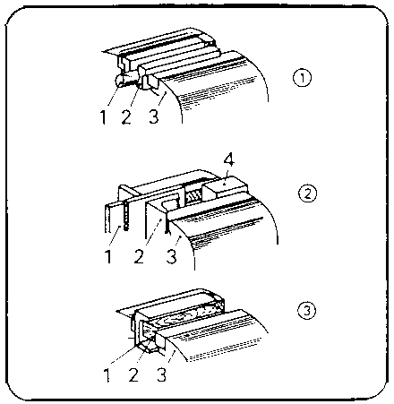
Figure 4.3
Demonstrations should show these effects when cutting a broad and a narrow workpiece each. The trainees will see that the saw will cut better when many teeth are cutting at the same time. This requires a different handling of saws.
In this context the trainees should be shown the proper posture and guidance of the saw.
The “Trainees’ Handbook of Lessons” contains specific hints for this subject which must be taken into account.
How to handle the saw
The trainees have to be shown the close connection between a vertical guidance of the cut and the proper clamping of the workpieces. The following examples need particular explanation:
- Clamping of flat workpieces for sawing on their broad side.
- Clamping of sheet metal and sawing with upward pushing direction.
- Clamping and repeated re-clamping when sawing tubes.
- Fixing of angle sections and sawing on the broad side only.
- Sawing of deep cuts with the saw frame swivelled by 90°.
These facts should be further illustrated when working in the workshop.
3.2. Exercises
If it was not possible to include the individual demonstrations into the instructions, they should be performed right now before the exercises.
If the trainees avail of only little practical skills, they should do some preliminary exercises on any small workpieces:
- simple cutting of flat and square steel
- cutting of tubes and angle sections
- sawing of straight and angular recesses.
But it is also possible to begin with the first exercises contained in the “Instruction Examples for Practical Vocational Training” at once.
However, it is necessary to prepare any individual exercise by a brief “Job-related instruction”. Within this context the trainees are shown a finished workpiece in order to make them familiar with the aim and purpose of this exercise.
The instructor must have completed such a workpiece by himself so as to know the problems involved in manufacturing it.
This makes it possible to determine the main points in evaluating the trainees’ performance and to advise the trainees on problems involved.
During these lessons of special instruction the trainees have to place the sequences of operations and working drawings of the training examples on their desks so that they can make notes therein.
All the trainees can carry out these exercises simultaneously, if the required number of working tools is available. If this is not the case, the trainees will be divided into groups based on the respective tasks and the number of the working tools available.
Those trainees who cannot start their practice of sawing immediately should do some other jobs in the workshop first:
- selection and preparation of the initial materials,- checking and minor repair work on working tools under supervision of an instructor; other exercises can reinforce the skills of working techniques acquired earlier.
3.3. Examples for recapitulation and tests
This section comprises questions for consolidating and testing the acquired knowledge and skills. Each question is provided with the respective answer. Questions which are also contained in the “Trainees’ Handbook of Lessons” are marked with the letter “A”.
1. What is the purpose of sawing?
(Cutting of workpieces in a
narrow saw kerf in order to divide them or to provide them with slots or cuts.)
2. How do the various types of saw blades
differ?
“A” (Design of angles at the saw tooth, number of teeth on
a length of 25 mm.)
3. What saw blade do we use when sawing steel of normal
hardness?
(Saw blade with medium tooth pitch and cutting-type chip
formation.)
4. Why is the free cutting action necessary for saw
blades?
“A” (This is to prevent them from jamming in the kerf.)
5. Which are the common design-based ways of achieving the free
cutting action?
(Raker-setting of saw teeth, wave-setting of teeth.)
6. What is to be taken into consideration when clamping a
workpiece for sawing purposes?
“A” (The workpiece is to be clamped
in a way that allows a vertical sawing cut and prevents the workpiece from
springing and slipping.)
7. Which is the most important clamping device for
workpieces?
“A” (Vice.)
8. Which types of workpieces have to be clamped in vices by
means of protective jaws?
(Workpieces with coated or sensitive surfaces.)
9. Why must we guide the saw in such a way that as many teeth as
possible are cutting at the same time?
“A” (If only a few teeth are
cutting, there will be the danger of hooking in and breaking out of teeth.)
10. What is to be taken into consideration when sawing off
workpieces?
“A” (Immediately before the workpiece is sawn off, the
pressure on the saw must be reduced so that the saw blade will not be damaged by
a torn off workpiece.)
11. How is the saw to be handled when sawing thin metal
sheets?
“A” (Saw must be held slightly upwards in the pushing
direction.)
12. How is the saw to be handled when sawing tubes and sectional
steel?
“A” (Tubes and steel sections must not be sawn off in one
pass, but they have to be reclamped during sawing so that as many teeth as
possible will be cutting at the same
time.)
4. Application of the working technique of “Manual Sawing”
The sequence of exercises can follow the order of the 7 (or 6) aces mentioned in the “Instruction Examples for practical vocational training - Manual Sawing”.
These “Instruction Examples...” comprise a list of materials (initial materials, hand tools, measuring and testing tools, accessories) as well as the sequence of operations for manufacturing these workpieces. Thus, the trainees avail of the necessary information to begin their exercise-related work. Should the quality of the manufactured workpieces be considered insufficient, the trainee has to carry out comprehensive preliminary exercises. To do so, any waste components will do. If the skill has been practised sufficiently, the envisaged workpiece can be manufactured.
The following hint should be taken into consideration:
The trainee has to do all the work alone - from the very beginning (cutting of initial material) till the completion of the workpiece.
This is the only way to guarantee a just evaluation of the achievements. Should the offered “Instruction Examples...” not be used in the exercises, then it is also possible to select other workpieces. In this case all the working techniques acquired earlier should also be practised with these workpieces.
4.1. Instruction examples
What follows is a brief description of the individual training examples in order to give a survey of those workpieces on which the previous knowledge is to be verified:
Instruction Example 4.1.
Spacers and Pin Drifts
Flat steel and aluminium sheets as well as round material of copper and brass are used to practise simple, straight saw cuts. The finished parts can be employed as necessary accessories in workshops: spacers for clamping, pin drifts for loosening pin connections.
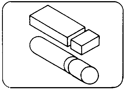
Figure
Instruction Example 4.2.
Stands and Supports
Channel sections and steel tubes serve to practise the specific skill of cutt-off sawing. Repeated re-clamping of the workpiece is a must.
Channel can be further worked in order to manufacture drill stands etc. The instruction examples 2.3. and 7.4. give a description of continuing this work. The tubes can be prepared in such a way that they can serve as supports for instruction example 4.6.
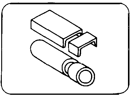
Figure
Instruction Example 4.3.
Container
Light metal or steel sheets or tubes will be sawn to given dimensions to practise mitre cuts. After glueing, soldering or welding, these components can serve as containers for pins or scribers.

Figure
Instruction Example 4.4.
Vee-shaped-Attachment
Steel sheet will be cut to size by long and straight sawing cuts; solid square steel will be sawn by mitre cuts (the required angle will be given by the instructor). After-having connected these components by bolts or rivets this workpiece can be used as accessory for clamping cylindrical workpieces.
Figure
Instruction Example 4.5.
Steel Square
Long and straight sawing cuts of high precision are practised on steel sheets. Once completed, the workpiece can be used in the workshop.
Figure
Instruction Example 4.6.
Angle-Steel Frame Table
Straight and mitre cuts serve to practise the technique of joining angle steel to form a frame.
Emphasis is to be laid on the peculiarities of straight and mitre cuts. Welded with the supports mentioned in instruction example 4.2., a frame for a table is produced which can be provided with an insert (of steel or wood) so as to form a table for putting down tools etc. in the workshop.
Figure
Instruction Example 4.7.
Wall-Shelf-Bracket
Angle steel is used to practise mitre cuts and cut-outs. When combined with other working techniques, a set of brackets for wall shelves can be produced.
These brackets can be bolted into the wall and provided with a board of any length - and this results in a useful and solid place for laying down workshop accessories
Figure
4.2. Criteria for practical training
It is recommended to determine some major points of observation and evaluation of the work performed.
The following criteria may serve as a guideline:
Does the trainee select the appropriate saw blade?
Does he fix the saw blade in the proper way (in the pushing direction)?
Is the workpiece clamped as required?
Does the trainee use available accessories?
Does the trainee employ cutting oil for sawing?
Does the trainee pay attention to vertical guidance of the saw?
Does the trainee re-clamp sections during sawing or does he saw off in one pass?
Does the trainee pay attention to the fact that there must be as many teeth as possible cutting at the same time even when sawing thin workpieces?
Does the trainee’s tool comply with the labour safety requirements?
5. Captions and legends of the “Manual Sawing” transparencies series
|
Transparency No. 4.1.: |
Design and operation of a hand hacksaw | |
| |
(1) Hand hacksaw | |
| |
|
1 - handle |
| | |
2 - fixed clamping dog |
| | |
3 - retaining pin |
| |
|
4 - saw blade |
| |
|
5 - saw frame |
| |
|
6 - adjustable clamping dog with wing |
| |
(2) saw teeth in action | |
|
Transparency No. 4.2.: |
Fixing and free cutting action of saw blade | |
| |
(1) Fixing of saw blade | |
| | |
1 - clamp dog |
| |
|
2 - rivet or pin |
| |
|
3 - saw blade |
| |
(2) action of saw blade with raker-set teeth | |
| |
(3) action of saw blade with wave-set teeth | |
| | |
4 - free cutting action |
|
Transparency No. 4.3.: |
How to clamp a workpiece for sawing | |
| |
(1) Clamping a round workpiece with vee clamp as attachment | |
| |
|
1 - workpiece |
| |
|
2 - vee clamp |
| |
|
3 - vice |
| |
(2) clamping a metal sheet with angle clamp as attachment |
|
| | |
4 - spacer |
| |
(3) clamping a channel section with hardwood attachment |
|
|
| ||||||||||||||||||||||||||||||||||||||||||||||||||||||||||||||||||||||||||||||||||||||||||||||||||||||||||||||||||
Manual Working of Material/Metal - Course: Manual working of metal. Methodical course-guide for instructors (Institut f�r Berufliche Entwicklung, 218 p.)
Filing
1. Objectives and contents of practical vocational training in the working technique of “Filing”
By concluding their training the trainees shall have a good command of the working technique of “Filing”. Therefore, the following objectives are to be achieved:
Objectives
- Knowledge of purpose and application of the filing technique.
- Proper handling of files and capability of filing all surfaces, edges and break-throughs to size,
- Capability of selecting and properly using the appropriate tools and accessories.
- Capability of making decisions on quality independently.
The following contents have to be imparted to the trainees:
Contents
- Purpose of filing
- Tools and accessories
- Effects and handling of files.
2. Organizational preparations
In order to guarantee a trouble-free development of the instructions, exercises and practical work it is necessary to prepare this training appropriately.
The following steps have to be taken:
2.1. Preparations for instructions on labour safety
Prior to the exercises, a brief instruction on the proper use of tools and equipment has to be given. This comprises also hints for accident-free work.
The main emphasis is to be laid on:
- Files with crack-free file handles must be used only.- New file handles are to be drilled and enlarged in relation to the tang of the file and then fixed by light blows with the hammer.
- Files are to be protected from dropping and must not be laid one above the other.
- Hardened components must not be filed - danger of slipping!
Familiarity with these hints has to be confirmed by the trainees’ signatures in a control book.
2.2. Provision of teaching aids
- For demonstration purposes during the instructions, a vice has to be firmly installed at the place,
- The “Trainees’ Handbook of Lessons - Filing” is to be handed out to the trainees in sufficient numbers.
- When using the transparencies series of “Filing”, check whether they are complete (transparencies nos. 5.1. - 5.5.) and whether the overhead projector is functioning. (Check the operating conditions at the place of use and make sure of the proper mains supply!)
- Surveys etc. which are to be written on the blackboard have to be completed prior to the instruction.
- All the tools and accessories mentioned in section 3 (for filing purposes) should be kept ready for illustration purposes.
2.3. Provision of working tools and materials
- The “Instruction Examples for Practical Vocational Training -Filing” must be handed out to the trainees in sufficient copies to provide them with the theoretical foundations for the exercises to be carried out.
- The initial materials necessary for the exercises have to be prepared and laid out in sufficient numbers according to the materials mentioned in the “Instruction Examples...”
- Each trainee is to be provided with a workbench at which a vice is firmly installed (check the proper height of this vice!)
- The trainees’ workbenches have to be fully equipped with tools and accessories according to the envisaged exercises.
Recommended basic equipment:
- steel rule, vernier caliper, bevelled edge square, protractor
- steel scriber, prick punch, dividers
- hand hacksaw, locksmith’s hammer
- bastard and smooth files 200 - 300 mm (flat, three-square, round)
- warding file (flat)- In order to carry out the necessary preliminary work (drilling), bench-type or column-type drilling machines with necessary clamping devices (machine vices, holding clamps, C-clamps) are necesary.
- Before the exercises are carried out, the drilling machines must be checked in order to find out whether their functionality complies with the requirements of labour safety,
2.4. Time schedule
Time planning is recommended for the following training stages:
- introduction to the working technique in the form of instructions
- necessary demonstrations
- job-related instructions to prepare the exercises
- carrying-out the exercises
- recapitulations and tests.
The necessary time-share depends on the respective training conditions. Most of the time is to be allocated to the exercises.
3. Recommendations for practical training in the working technique of “Filing”
The following paragraphs comprise proposals on conducting trainee instruction, the demonstration of working techniques as well as the exercises and tests.
The following sequence of stages is recommended:
- Introductory instruction with demonstrations from the “Trainees Handbook of Lessons”
- Exercises in “Filing” based on the “Instruction examples 5.1. to 5.6.”
- Final test of theory knowledge based on the contents of “Examples for Recapitulations and Tests”
Practical skills should be evaluated immediately after having received the trainees’ test workpieces. Knowledge of theory should be constantly checked, however, it is recommended that a final test paper should be written after concluding the exercises.
3.1. Introductory instruction
If possible, this instruction should be conducted in a classroom.
Make sure, that the trainees put down necessary and supplementary notes or answers to questions in their “Trainees’ Handbook of Lessons”.
Instruction can be carried out on the basis of the main points contained in the “Trainees’ Handbook of Lessons”. The two major subjects of “Purpose of Filing” and “Tools and Accessories for Filing” should be taught in such a way that all the teaching aids available are employed.
Purpose of filing
This subject can be explained to the trainees by employing workpieces which had been worked with files. The trainees will learn that these workpieces reveal all the signs of a single-piece production.
The trainees will learn - and this is to be emphasised - that the finishing of surfaces or shapes is one of the major applications of the filing technique and that they must have a good command of this skill.
Tools and accessories
Introducing the subject of files should be begun with a flat file. The design of this tool can be illustrated by referring to the original tool and to the illustrations contained in transparency no. 5.1.
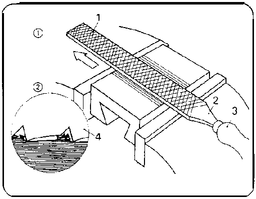
Figure 5.1
This is also the time to demonstrate the kinds of fixing file handles to the file blade. This will be followed by introducing the other types of files contained in the list of the “Trainees’ Handbook of Lessons”:
- flat file
- square file
- triangular file (three-square file)
- round file
- half-round file
- crossing file - barrette file
- knife-edge file.
The demonstration of original tools can be supported by showing the illustrations contained in the transparencies nos. 5.2. and 5.3.
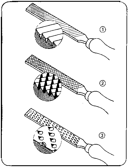
Figure 5.2
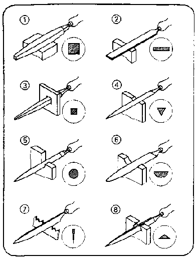
Figure 5.3
The trainees have not only to know the types of files but also how to use them. In this context the instructor has to mention that the use of files depends on their sizes and kinds of cut (single-cut, double-cut, rasp-cut).
The following survey (written on the blackboard) can be employed to finalise the instruction:
|
Designation Cut |
no. |
File surface |
Use of file |
Fineness of file |
|
rough-cut file |
0 1 |
rough (stroke of file tangible and visible) |
for oversize of 0.5 mm and mor |
very coarse |
|
second-cut file |
2 |
fine (file stroke no longer tangible but still visible) |
for oversize of less than 0.1 mm |
|
|
smooth-cut |
3 |
|
|
|
|
dead-smooth |
4 |
very fine (file stroke neither tangible nor visible) |
for fits and best surface finish | |
|
super-smooth |
5 | | |
very fine |

The introduction of accessories should be linked with remarks on their respective application:
- vice
- vee clamps
- angle clamps
- protective jaws
- clamping jaws for round material
- clamping jaws for bolts and thread clamps
- saw sharpening vice
- hand vice and pin vice
- sheet metal dog vice
This is also the appropriate moment to mention that such accessories can be easily produced by everybody. The subsequent working techniques contained in this course will give some ideas of how to manufacture these accessories during practical exercises.
Action of filing, postures of trainees and guidance of files Transparency no. 5.1. as well as the illustrations contained in the “Trainees’ Handbook of Lessons” can be employed to describe the action of filing. The different actions of milled and chiselled files should be explained. It is to be mentioned that the use of chalk on surfaces will support the job of fine finishing.
The instructor must demonstrate the correct posture and guidance of the file when instructing the group. This can be demonstrated very effectively, if a vice is available in the classroom. If this is not the case, the sequence of motions has to be demonstrated quite clearly.
The instructor has to emphasise that the file must be moved by the motion of the arms only and that it must work in pushing direction only.
After these demonstrations each trainee should demonstrate the filing movement and posture. The instructor should see to it that all the trainees take part in evaluating the performance of their fellow-trainees.
Handling of files
If there is a vice available in the classroom, the following major subjects should be imparted to the trainees within the framework of the introductory instruction. The main method involved in these instructions should be that of demonstrating the practical use of these files. If such a demonstration cannot be given in the classroom, the instruction is to be continued in the workhsop.
The instructor has to show how differently large, medium-size and small files have to be handled. Special emphasis is to be laid on the corect handling of file blades by the guiding hand. Subsequently, the kinds of stroke (oblique stroke, cross stroke, longitudinal stroke) have to be demonstrated when filing flat surfaces. The trainees have to see that these kinds of stroke, when applied step by step, will improve the degree of evenness and surface finish.
Transparency no. 5.4, should be employed as an additional teaching aid. Subsequently, testing of faces by means of bevelled steel straight-edge and bevelled edge square should be demonstrated. There should be separate demonstrations of filing curved surfaces on small- and large-size external radii materials, stressing the different way of handling the file.
This fact is also illustrated by transparency no, 5.5. and illustrations in the “Trainees’ Handbook of Lessons”. The instructor has to show how internal round surfaces have to be filed with different files depending on the size of the internal radii (round file, half-round file, crossing file). This should be followed by instructions in checking these radii with radius gauges and fillet gauges.
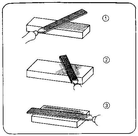
Figure 5.4
Pre-finished workpieces (sawn or drilled) must be prepared to demonstrate the working technique of filing cuts and breakthroughs. Depending on the shape of the cut or break-through, the instructor has to select the appropriate form of the file. A separate section of instruction serves to demonstrate the filing of chamfers on large-size and small-size workpieces (employing a saw sharpening vice) as well as on round materials (bolts). The different ways of handling the files have to be underlined. This is also supported by the illustrations contained in the “Trainees’ Handbook of Lessons”. The instructions should be concluded by the trainees’ answers to questions asked in the “Trainees’ Handbook of Lessons”.
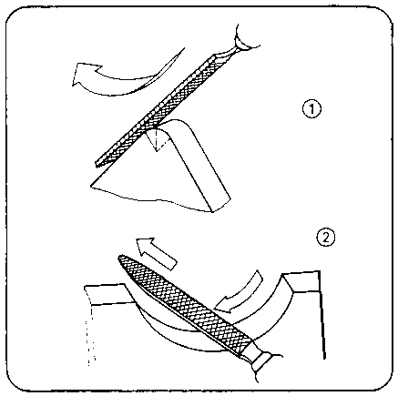
Figure
5.5
3.2. Exercises
If it has not been possible to include the individual demonstrations in the instructions, this should be done right now prior to the exercises. Subsequently, it will be possible to commence with the first exercise contained in the “Instruction Examples for Practical Vocational Training”. However, it is necessary to prepare every individual exercise by a “job-related instruction” during which the trainees are shown a finished workpiece in order to demonstrate the objectives and purpose of the exercise.
|
The instructor must have made such a workpiece himself in order to be familiar with all the problems which might arise in producing such a workpiece. |
Thus, the instructor can mention the criteria for evaluation as well as the problems involved in manufacturing such a workpiece. During these instructions the sequences of operation and the working drawings of the “Instruction Examples” should be placed on the desks so that the trainees can make notes therein. All the trainees can carry out these exercises simultaneously, if the material prerequisites are given (availability of a sufficient number of tools etc.). This being the case, any individual exercise should be carried out individually with each trainee being allowed to take the time he needs.
If this is not the case, the trainees have to be grouped in teams depending on the subject of work and number of the available working tools.
Trainees who cannot begin with filing should do other jobs in the workshop:
- selection and preparation of initial materials,
- checking and minor repair work on working tools under the supervision of the instructor,
- exercises which consolidate skills in the working techniques acquired in the past.
3.3. Examples for recapitulation and tests
This section comprises questions which are to consolidate and test the acquired skills and knowledge. Each question is provided with the respective answers. Questions which are also contained in the “Trainees’ Handkook of Lessons” are marked with the letter “A”.
1. What is the purpose of filing?
(To change flat or curved
surfaces or edges of pre-worked components in terms of dimensions, forms and
surface finish),
2. When is it useful to employ files?
“A” (In case
of single-piece production, for repair work, and sometimes for assembly work).
3. Which of the file forms is the mainly used
form?
“A” (Flat file).
4. Which type of cut is used for filing general steel grades and
cast iron?
“A” (Double-cut file).
5. What is the order of files form coarse to fine surface
finish?
(Roughing file - bastard file - coarse finishing file -finishing file
- fine finishing file - superfine finishing file).
6. How do we select files?
(We have to consider the form of
the surfaces or edges to be filed, the hardness of the material to be filed, the
size of the surface to be filed, the amount of work and the surface finish).
7. How does a file act?
(Its many wedge-shaped teeth
penetrate into the workpiece by means of pressure from above and to the front
and remove chips).
8. Why are milled files well-suited to soft
materials?
“A” (They are provided with very sharp teeth and small
wedge-angles resulting in a cutting action).
9. Why are chiselled files well-suited to hard
materials?
“A” (Their teeth have large wedge angles and exert a
shaving effect).
10. Why must the files be operated with the arms in motion and
the upper part of the body kept steady?
“A” (Otherwise the motion
of the file would become arch-like instead of being horizontal and the filed
surface would not be flat).
11. What is the difference in handling large and medium-size
files?
(In the case of large-size files the guiding hand rests completely on
the file blade, whereas thumb and finger of the guiding hand will grip the file
blade of medium-size files).
12. Which kinds of strokes have to be employed successively when
filing flat surfaces?
“A” (Oblique stroke, cross stroke,
longitudinal stroke).
13. Why can only cross-stroke files be used to achieve flat
surfaces of good surface finish?
“A” (The alteration in the
direction of working makes it possible to recognize elevations and depressions
on the worked surface very well by the working tracks left on it).
14. What is typical of file movements when filing small external
radii?
“A” (Rocking feed movement opposite to the radius in the
longitudinal direction of the curvature).
15. Which are the requirements to be met when using files for
working internal radii?
“A” (The file must have a smaller radius
than the curvature of the workpiece).
16. What is the difference in filing chamfers on large and small
components?
“A” (With large-size components the file position will
be 45 upwards; with small-size components the file position will be horizontal -
the component should be fixed in a saw sharpening vice).
17. Which are the conditions to be met when clamping the
workpiece?
“A” (You must clamp the workpieces so firmly and safely
that the components will not spring or slip. The file position must be
horizontal).
18. Which are the proper devices for clamping
workpieces?
“A” (Vice, sheet metal dog vice, protective jaws of
soft metal, clamping jaws for round pieces, vee clamps, thread
jaws).
4. Application of the working technique of “Filing”
The sequence of exercises can follow the order of the 6 exercises mentioned in the “Instruction Examples for Practical Vocational Training”.
These “Instruction Examples...” comprise a list of materials (initial material, working tools, measuring and testing tools, accessories) as well as the sequence of operations for the manufacture of these workpieces; also contained is an illustrative working drawing.
Thus, the trainees have the necessary information to begin their exercises.
If the quality of the produced workpieces should be considered insufficient, the trainee has to carry out comprehensive preliminary exercises. For this purpose any waste parts may be used. If the respective skill has been practised sufficiently, the envisaged workpiece can be produced.
The following hint should be taken into consideration:
The trainee has to do all the work involved alone - from the very beginning till completion.
This is the only way to guarantee a just evaluation of the achievements.
Should the offered “Instruction Examples...” not be used in the exercises, then it is also possible to select other parts for practising. In this case all the working techniques acquired earlier should be also practised when working these pieces.
4.1. Instruction examples
What follows is a brief description of the individual instruction examples in order to give a survey of the parts to be produced for practising the knowledge acquired:
Instruction Example 5.1.
Step Block
Filing of flat surfaces of square steel to finishing quality and of sawn out, stepped surfaces of small dimensions. Together with the parts produced as instruction examples 2.2., 5.2. and 5.5., it can be used as part of a set of clamping tools for an upright drilling machine.
Figure
Instruction Example 5.2.
Sliding Block
Filing of flat and stepped small-size surfaces of square steel to finishing quality and angularity. Additionally, the trainees practise filing of chamfers. Together with the components produced as instruction examples 2.2., 5.1. and 5.5. it will form another part of the set of clamping tools for an upright drilling machine.
Figure
Instruction Example 5.3.
Locksmith’s Hammer
Filing of flat and inclined surfaces, radii, a break-through and chamfers on square steel. After being hardened, the locksmith’s hammer can be fitted with a handle and be used in the workshop.
Figure
Instruction Example 5.4.
Hexagon Socket Wrench
This exercise concentrates on filing small-sized, stepped surfaces on round steel materials. Angularity and accuracy to size are essential. A new degree of difficulty is added by filing a chamfer on round material.
After hardening this workpiece it may be used for mounting hexagonal socket-haed bolts in the workshop.
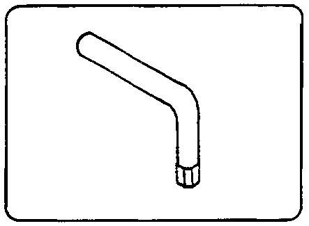
Figure
Instruction Example 5.5.
Box Wrench
This filing practise concentrates on flat and curved narrow steel plate surfaces. The trainee will also practise how to produce a true-to-size hexagonal break-through.
Being part of a set of clamping tools for an upright drilling machine the size of this part complies with the size of the components produced as instruction examples 2.2., 5.1. and 5.2.
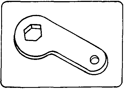
Figure
Instruction Example 5.6.
Bevel
Here, too, flat and curved surfaces of flat steel are filed to finishing quality. Extremely difficult tasks are associated with a long break-through on a single component. This bevel can be used for transferring angle values in the workshop.
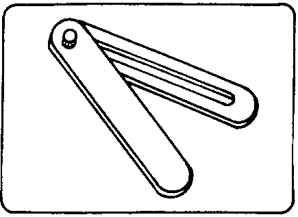
Figure
4.2. Criteria for practical training
It is recommended to determine some major points of observation and evaluation of the work to be performed.
The following criteria can serve as a guideline:
Flat surfaces and edges
- Is the trainee’s posture correct?
- Does the trainee handle the file exactly horizontally or does the file “swing” over the surface?
- Does the trainee apply the oblique stroke technique to roughing?
- Does the trainee supply the cross stroke technique to achieve flat surfaces?
- Does the trainee apply longitudinal strokes to finishing filing?
- Does the trainee know how to check with the bevelled steel straight-edge or bevelled edge square?
Curved surfaces
- Does the trainee handle the file in the longitudinal direction of the round surface (with small-size round forms) and does he rock the file opposite to the radius?- Does the trainee handle the file at right angles to the radius (with large-size round forms) and does he incline the file slightly?
- Does the trainee use a file with a smaller radius that the curvature for big internal radii?
Cut-outs and break-throughs
- Does the trainee employ the proper kind and size of file (in relation to cut-out and break-through)?
Chamfer
- Does the trainee employ the file at an angle of 45 with the file pointing upwards for large-size workpieces?- Does the trainee use the saw sharpening vice when filing small-size components?
- Does the trainee handle the file laterally inclined and tilting towards the outside when filing round workpieces?
5. Captions and legends of the “Filing” transparencies series
|
Transparency no. 5.1.: |
Design and action of a file (1) flat file | |
| | |
1 - file blade |
| |
|
2 - tang |
| | |
3 - handle |
| |
(2) chip removal by the file teeth | |
| | |
4 - file tooth |
|
Transparency no. 5.2.: |
Kinds of cuts | |
| |
(1) single-cut file | |
| |
(2) double-cut file | |
| |
(3) rasp-cut file | |
|
Transparency no. 5.3.: |
Use of files | |
| |
(1) square rubber file | |
| |
(2) flat file | |
| |
(3) square file | |
| |
(4) triangular file | |
| |
(5) round file | |
| |
(6) half-round file | |
| |
(7) knife-edge file | |
| |
(8) barrette file | |
|
Transparency no. 5.4.: |
Filing of flat surfaces | |
| |
(1) oblique-stroke filing | |
| |
(2) cross-stroke filing | |
| |
(3) longitudinal-stroke filing | |
|
Transparency no. 5.5.: |
Filing of curved surfaces | |
| |
(1) filing of external radius - employing a flat file |
|
| |
(2) filing of internal radius - employing a half-round file. | |
|
| ||||||||||||||||||||||||||||||||||||||||||||||||||||||||||||||||||||||||||||||||||||||||||||||||||||||||||||||||||
Manual Working of Material/Metal - Course: Manual working of metal. Methodical course-guide for instructors (Institut f�r Berufliche Entwicklung, 218 p.)
Scraping of Plane Surfaces
1. Objectives and contents of practical vocational training in the working technique of “Scraping of Plane Surfaces”
By concluding their training, the trainees shall have a good command of the working technique of “Scraping of Plane Surfaces”. Therefore, the following objectives must be achieved:
Objectives
- Knowledge of purpose and application of scraping and checking against master plates.- Good command of the various working techniques of scraping and surfacing as well as capability of planing workpieces.
- Capability of selecting the appropriate tools and accessories and of using them properly.
- Capability of making decisions on quality independently.
Therefore, the following contents have to be imparted to the trainees:
Contents:
- Purpose of scraping
- Scraping tools
- Purpose of checking against master plates
- Testing tools and accessories for checking against master plates
- Action of scraping
- Technological process of planing flat surfaces.
2. Organizational preparations
In order to guarantee a trouble-free development of the instructions, exercises and practical work it is necessary to prepare this training appropriately.
2.1. Preparations for instructions on labour safety
Prior to the exercise a brief instruction in the proper use of working tools has to be given. This comprises also hints for accident-free work. The main emphasis is to be laid on:
- Flawless scrapers must be used only
- The scraper handles must not show any cracks
- Workpieces must be clamped in such a way that they do not become distorted by the clamping forces
- Scraped surfaces must be protected from damage - they must be covered
- Surfaces of tools for checking against master plates must be protected from damage - to be oiled after use!
Familiarity with these hints has to be confirmed by the trainees signatures in a control book.
2.2. Provision of teaching aids
- For the purpose of demonstrations during the instructions a small surface plate has to be installed at a workbench, and a vice should also be at the site.
- The “Trainees’ Handbook of Lessons” - Scraping of Plane Surfaces” is to be handed out to the trainees in sufficient numbers.
- When using the transparencies series of “Scraping of Plane Surfaces”, check whether they are complete (transparencies nos. 6.1. - 6.3.) and whether the overhead projector is functional. (Check the operation conditions at the place of work and make sure of the proper mains supply!)
- Surveys etc. which are to be written on the blackboard have to be completed prior to instruction.
- All the tools and accessories mentioned in section 3 should be kept ready for illustration purposes.
2.3. Provision of working tools and materials
- Sufficient copies of the “Instruction Examples for Practical Vocational Training - Scraping of Plane Surfaces” must be handed out to the trainees to provide them with the theoretical foundations of the exercises to be carried out.
- The initial materials necessary for the exercises have to be prepared and laid out in sufficient numbers according to the materials mentioned in the “Instruction Examples...”.
- Each trainee is to be provided with a workbench at which the respective clamping devices and surface plates are firmly fixed and which is sufficiently lit.
- The trainees’ workbenches have to be fully equipped with tools and accessories according to the envisaged exercises.
Recommended basic equipment:
- steel rule, bevelled steel straight-edge, vernier caliper
- bastard and smooth files 200 - 300 mm (flat)
- hand hacksaw
- locksmith’s hammer, aluminium hammer
- flat scraper, pull-type scraper
- checking ink, inking block, levelling straight-edges
- bench-type or column-type drilling machines with the appropriate clamping devices (machine vice, holding clamps, C clamps) for necessary preparations (drilling) in certain exercises.
- Before the exercises are carried out, the drilling machines’ compliance with the requirements of labour safety has to be checked.
2.4. Time schedule
Time planning is recommended for the following training stages:
- introduction to the working techniques in the form of instructions
- necessary demonstrations
- job-related instructions for preparing the exercises
- carrying-out the exercises
- recapitulations and tests.
The necessary time share depends on the respective training conditions. Most of the time is to be allocated to the exercises.
3. Recommendations for practical training in the working technique of “Scraping of Plane Surfaces”
The following paragraphs comprise proposals on conducting trainee instruction, the demonstration of working techniques as well as the exercises and tests. The following sequence of stages is recommended:
- Introductory instruction with demonstrations from the “Trainees’ Handbook of Lessons”.
- Exercises in scraping according to the “Instruction Examples 6.1. - 6.5.”.
- Final test of theory knowledge based on the contents of “Examples for Recapitulation and Tests”.
Practical skills should be evaluated immediately after handing over the finished workpieces. Knowledge of theory should be constantly checked. However, it is recommended that a final test paper should be written after concluding the exercises.
3.1. Introductory instruction
If possible, this instruction should be conducted in a classroom. Make sure that the trainees put down necessary and supplementary notes or answers to questions in their “Trainees’ Handbook of Lessons”.
Instruction can be carried out on the basis of the main points contained in the “Trainees’ Handbook of Lessons”.
Purpose of scraping
This subject can be explained to the trainees by way of a short lecture. The instructor has to emphasise that manual scraping ranks among the high-grade manual techniques and that this working technique is mostly replaced by machine processes in modern industry. However, the trainees have to understand that machine processes cannot be employed everywhere and that they are not always worth while.
Scraping tools
The following tools and their use should be introduced by showing some original tools and illustrations contained in transparency no. 6.1.
- flat scraper (push-type scraper)
- pull-type scraper
- curved bearing scraper (half-round scraper)
- three-square scraper.
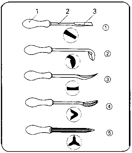
Figure 6.1
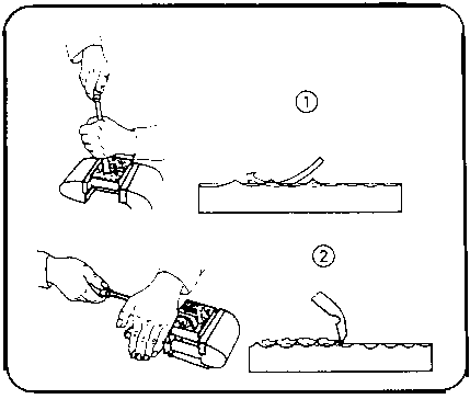
Figure 6.2
Transparency no. 6.2. can illustrate the use of flat and pull-type scrapers. Subsequently, it has to be stressed that these tools have to be ground absolutely sharp and whetted clean. The whetting has to be demonstrated, because it is rather difficult to give a clear-cut description of the motions involved.
Purpose of checking against master plates
It is necessary to explain this quality checking technique to the trainees.
The instructor clearly points out that scraping and checking against master plates are two interactive processes.
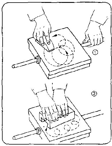
Figure 6.3
Transparency no. 6.3.
will illustrate this working method.
Testing tools and accessories for checking against master plates
- surface plate
- levelling straight-edge
- planing straight-edge
- planing tool for slide guides.
The following accessories are to be mentioned:
- checking ink
- inking block.
If the original tools are not available, the illustrations contained in the “Trainees’ Handbook of Lessons” can support and supplement the instruction.
Action of scraping
Transparency no. 6.2. and the illustration contained in the “Trainees’ Handbook of Lessons” supplement the instruction of this major topic. This includes a demonstration of the proper angle of inclination (45 degrees) as well as the characteristic movements of the hand when working with the scraper.
Technological process of planing flat surfaces
First, the individual steps of the process must be described and - if possible - they will be followed by demonstrations then.
This demonstration includes the following steps:
1. rough-scraping (pre-scraping)
2. checking
3. spot-scraping
4. finish-scraping and pattern-scraping
The “Trainees’ Handbook of Lessons” contains a detailed description of these steps. The trainees must avail of a good theoretical knowledge of these processes before they can begin their practical work. Therefore, it is advisable that the trainees should answer the questions contained in the “Trainees’ Handbook of Lessons”.
3.2. Exercises
If it has not been possible to include the individual demonstrations in the instructions yet, this shall be done prior to the beginning of the exercises.
Subsequently, it will be possible to commence with the first exercises contained in the “Instruction Examples for Practical Vocational Training”. However, it is necessary to prepare every individual exercise by a brief “job-related instruction” during which the trainees are shown a finished workpiece in order to demonstrate the objectives and purpose of this exercise.
|
The instructor must have finished such a workpiece by himself in order to be familiar with all the problems which might arise in producing such a workpiece. |
Thus, the instructor can mention the main points of evaluation as well as all the problems involved in manufacturing such a workpiece. During these instructions the Sequences of operations and the working drawings should be placed on the desks so that the trainees can make some notes therein.
All the trainees can carry out these exercises simultaneously, if the necessary material is available (availability of a sufficient number of working tools etc.). This being the case, all the individual exercises should be carried out by the individual trainees without being pushed by time limits.
If there are not enough tools available, the trainees have to be grouped in teams depending on the application of the various tools:
team no. 1 - single-piece work according to the working drawings
team no. 2 - scraping exercises according to the “Instruction Examples 6.1. - 6.4.
team no. 3 - planing of the lathe bed - Instruction Example 6.5. (maximum: 3 trainees).
If there are still trainees who cannot participate in the exercises, they shall be given a task to consolidate their skills in previously learned working techniques.
3.3. Examples for recapitulation and tests
This section comprises questions which are to consolidate and test the acquired skills and knowledge. Each question is provided with the respective answer. Questions which are also contained in the “Trainees’ Handbook of Lessons” are marked with the letter “A”.
1. What is the purpose of scraping?
(To perform a smooth
finishing of pre-worked surfaces: they have to be smoothed, deviations of form
have to be removed or patterns have to be created.)
2. What kinds of workpieces are mainly worked by
scraping?
“A” (Sliding machine components - tool carriages, slide
bearings.)
3. When is it useful to employ scrapers?
“A” (When
fine finishing cannot be done by machines.)
4. Which are the scraping tools?
(Flat scraper, pull-type
scraper, curved bearing scraper, three-square scraper.)
5. When is it useful to employ flat scrapers?
“A”
(They are used for pre- and spot-scraping of plane surfaces, for removing bigger
amounts of chips.)
6. When is it useful to employ a pull-type
scraper?
“A” (It is used for finishing and pattern scraping of
plane surfaces and for removing minimum amounts of chips.)
7. What is to be done after having ground a
scraper?
“A” (Whetting of the cutting edge for removing burrs.)
8. What happens, if you omit this process?
“A” (The
burrs will break off during the scraping action and this will result in notches
on the cutting edge which, in turn, will make the cutting edge useless quickly.)
9. How is whetting to be performed?
(Both sides of the
cutting edge of the scraper have to be alternately pulled over the whetstone in
inclined position until the burrs are removed.)
10. What is the purpose of checking against master
plates?
(It is a technique for checking the quality of scraped surfaces
optically.)
11. What does “planing of a surface”
mean?
“A” (Planing means a permanent alternation of scraping and
checking against master plates until the surface is finished.)
12. Which testing tools and accessories do we need for checking
against master plates?
(Surface plate, levelling straight-edge, planing
straightedge, planing tool for slide guides, checking ink, inking block.)
13. How does the use of surface plates and levelling
straightedges differ?
“A” (Surface plate: used for small- and
medium-sized workpieces which are moved over the plate levelling straight-edge:
used for long and narrow surfaces of workpieces; the straight-edge is moved over
the workpiece.)
14. What is the purpose of using checking
paste?
“A” (Checking paste will make visible irregularities on the
worked surface.)
15. How are the chips removed when scraping?
(This is a
squeezing process during which the material will be removed at a cutting angle
of more than 90°.)
16. Which are the characteristic stages of planing a flat
surface?
“A” (Pre-scraping, checking, spot-scraping, checking,
finish-scraping.)
17. What is typical of pre-scraping processes?
“A”
(Long and powerful pushes with a flat scraper over the whole surface and
diagonal to the tool marks are typical of the pre-scraping processes.)
18. What is typical of spot-scraping processes?
“A”
(Short and curved pushes with a flat scraper over the peaks of the surface with
frequent changes of directions are typical of spot-scraping processes.)
19. What is typical of the finish-scraping
processes?
“A” (Gentle pulling of the pull-type scraper over the
peaks of the surface is typical of finish-scraping
processes.)
4. Application of the working technique of “Scraping”
The sequence of exercises can follow the order of the 5 exercises mentioned in the “Instruction Examples for Practical Vocational Training - Scraping of Plane Surfaces”. These “Instruction Examples...” also comprise a list of materials (initial material, hand tools, measuring and testing tools, accessories) and a sequence of operations as well as an illustrative working drawing.
Thus, the trainees avail of the necessary information to begin their exercise-related work.
Should the quality of the produced workpieces be considered insufficient, the trainee has to carry out comprehensive preliminary exercises. To do so, any waste parts will do. If the respective skill has been practised sufficiently, the envisaged workpiece can be produced. The following hint should be taken into consideration:
|
Scraping can be practised on pre-worked parts. The production of component parts and their assembly can be done by other trainees earlier. |
Should the proposed “Instruction Examples...” not be used in the exercises, then it is also possible to select other workpieces.
In this case all the working techniques described earlier should be also practised when working these parts.
4.1. Instruction examples
What follows is a brief description of the individual instruction examples in order to give a survey of those workpieces on which the previously acquired knowledge can be verified:
Instruction Example 6.1.
V-block
The trainees will practise the flat-scraping process on a flat steel surface (without given dimensions). Flat scrapers will be employed only.
Figure
Instruction Example 6.2.
Steel straight-edge
Two parallel, narrow surfaces of flat steel are worked with the flat scraper first and with the pull-type scraper then. After hardening the surface, the straight-edge can be used in the workshop.
Figure
Instruction Example 6.3.
Try Square
Two or, resp., three narrow surfaces of flat steel are worked in such a way that they are parallel to each other - in accordance with given dimensions. Parallelism will be checked by using dial gauges. After hardening the surfaces, the try square can be used in the workshop.
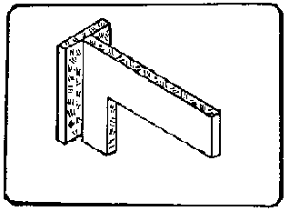
Figure
Instruction Example 6.4.
Centre Square
After the production of the components, this device can be used to practise pattern scraping of braiding patterns on steel sheets After hardening the surfaces this centre square can be used in the workshop.
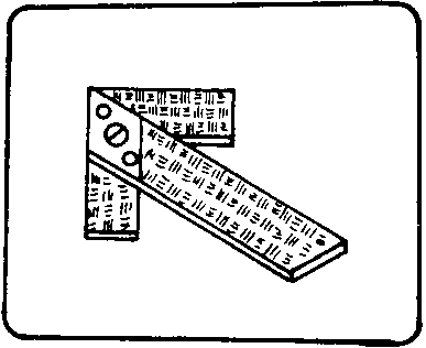
Figure
Instruction Example 6.5.
Lathe bed
Planing will be practised at an available lathe bed employing all the necessary techniques of scraping and checking against master plates.
Figure
4.2. Criteria for practical training
It is recommended to determine some major points of observation and evaluation of the work to be performed.
The following criteria can serve as a guideline:
Pre-scraping process
- Does the trainee employ long and powerful pushes which run diagonal to the working marks?
- Does the trainee apply the scraper with varying scraper positions?
- Does the trainee exert an increasing pressure?
Checking against master plates
- Does the trainee apply very thin films of the checking ink?
- Does he spread the checking ink evenly over the whole surface?
- Does the trainee recognise the surface appearance, and is he in a position to interpret it?
Spot-scraping
- Does the trainee apply the flat scraper in short, clearly defined curves?
- Does the trainee persistently work the peaks?
- Does he check regularly?
- Does he achieve the ratio of three peaks to one valley?
Finish-scraping and pattern scraping
- Does the trainee apply the pull-type scraper correctly?
- Is the trainee in a position to produce a regular pattern?
5. Captions and legends of the “Scraping of Plane Surfaces” transparencies series
|
Transparency no. 6.1. |
Kinds of scrapers | |
| |
(1) Flat scraper | |
| |
|
1 - handle |
| | |
2 - shank |
| | |
3 - blade |
| |
(2) Pull-type scraper | |
| |
(3) Half-round scraper (solid) | |
| |
(4) Half-round scraper (hollow) | |
| |
(5) Three-square scraper (hollow) | |
|
Transparency no. 6.2. |
Kinds of finish-scraping | |
| |
(1) Scraping with pushing actions | |
| |
(2) Scraping with pulling actions | |
|
Transparency no. 6.3. |
Checking against master plates | |
| |
(1) Spreading the checking ink over the surface plate using an inking block | |
|
|
(2) Rubbing of the workpiece on the surface plate | |
|
| ||||||||||||||||||||||||||||||||||||||||||||||||||||||||||||||||||||||||||||||||||||||||||||||||||||||||||||||||||
Manual Working of Material/Metal - Course: Manual working of metal. Methodical course-guide for instructors (Institut f�r Berufliche Entwicklung, 218 p.)
Drilling, Counterboring and Countersinking
1. Objectives and contents of practical vocational training in the working techniques of “Drilling, Countersinking and Counterboring”
By concluding their training, the trainees shall have a good command of the working techniques of “Drilling, Countersinking and Counterboring”. Therefore, the following objectives are to be achieved:
Objectives
- Knowledge of purpose and application of the drilling, countersinking and counterboring techniques.- Appropriate command of portable electric drills, bench-type drilling machines and upright drilling machines in compliance with the regulations on labour safety, they are in 5 position to determine tool values and to set up the machines appropriately.
- Capability of selecting and properly using the appropriate working tools and clamping tools.
- Precise command of the working processes involved in boring and counterboring of blind and through holes as well as capability of making independent decisions on quality.
The following contents have to be imparted to the trainees:
Contents
- Purpose of drilling, countersinking and counterboring
- Drilling machines and tools
- Action of drilling
- Setting of the tool values
- Clamping of tools and workpieces
- Technological sequence of drilling
- Purpose and application of counterboring/countersinking
2. Organizational preparations
In order to guarantee a trouble-free development of the instructions, exercises and practical work it is necessary to prepare this training appropriately. The following steps have to be taken:
2.1. Preparation of instructions on labour safety
Prior to the exercises a brief instruction in the proper use of tools and equipment (the machines in particular) has to be given. This comprises also hints for accident-free work. Any operation at the machines with freely movable (rotating) components involves dangers to health. Therefore, a strict compliance with the labour safety regulations is a must. In addition to the operating instructions of the respective machines, the following hints must be given:
- Use tight-fitting clothes and protective headgear! (Long hair must be covered under the headgear)- If there is no anti-glare device mounted on the machine, you must wear goggles!
- In order not to distract somebody from working with the machine, only one person has to work with the machine at a time.
- Setting up and cleaning work must not be done with the machine running!
- Workpieces must be secured against twisting and pulling up in relation to their sizes.
- Drilling needs adequate lubricating and cooling agents.
- Do not remove the chips by hand, use proper means (metal hooks, short metal bars)!
- Do not leave the machines until they have come to a standstill!
Familiarity with these hints has to be confirmed by the trainees’ signatures in a control book.
2.2. Provision of teaching aids
The “Trainees’ Handbook of Lessons” - Drilling, Countersinking and Counterboring” is to be handed out to the trainees in sufficient numbers.
When using the transparencies series of “Drilling, Countersinking and Counterboring”, check whether they are complete (transparencies nos. 7.1. - 7.6.) and whether the overhead projector is functioning (Check the operating conditions at the place of use and make sure of the proper mains supply!) Surveys etc. which are to be written on the blackboard have to be completed prior to the instruction. All the tools and accessories mentioned in section 3 should be kept ready for illustration purposes.
2.3. Provision of working tools and materials
The “Instruction Examples for Practical Vocational Training - Drilling, Countersinking and Counterboring” have to be handed out to the trainees to provide them with the theoretical foundations for the exercises to be carried out. The initial materials required for the exercises have to be prepared and laid out in sufficient numbers according to the materials mentioned in the “Instruction Examples...”. Two trainees should share a workbench with vice and - if possible - a drilling machine.
The trainees’ workbenches habe to be fully equipped with tools and accessories according to the planned exercises. Recommended basic equipment:
- steel rule, vernier caliper with depth gauge, centre square- steel scriber, marking gauge, centre punch
- locksmith’s hammer, hand hacksaw
- bastard and smooth files 350 mm (flat), (half-round)
- standard-type drills from 1.1 to 12 mm diameter soft-type drills 6.75; 8.0; 8.4; 9 mm diameter
- countersinks 60°; 75°; 90°
- Bench-type and upright drilling machines as well as (in individual cases of application) portable electric drills can be employed as drilling machines.- Prior to the exercises you have to check the functionality of the drilling machines according to the labour safety regulations.
2.4. Time schedule
Time planning is recommended for the following training stages:
- introduction to the working techniques in the form of instructions
- necessary demonstrations
- job-related instructions to prepare the exercises
- carrying-out the exercises
- recapitulations and tests.
The necessary time-shares depend on the respective training conditions. The schedule has to take into account that waiting times may occur at the machines during the stage of practical work, unless there is a sufficient number of drilling machines available.
Such waiting times should be bridged by minor and subject-related jobs.
3. Recommendations for practical training in the working techniques of “Drilling, Countersinking and Counterboring”
The following paragraphs comprise proposals on conducting trainee instruction, the demonstration of working techniques as well as the exercises and tests. We recommend two course variants:
Variant no. 1
This variant should be chosen for trainees with generally good achievements and receptiveness:
1.1. Introductory instruction with demonstrations according to the “Trainees’ Handbook of Lessons”1.2. Drilling. Countersinking and Counterboring exercises according to the “Instruction Examples 7.1. - 7.6.” and subsequent evaluation.
1.3. Final test of theory knowledge based on the contents of the “Examples for recapitulation and tests”.
Variant no. 2
This variant should be chosen for trainees with little previous knowledge or poor achievements.
2.1. Introductory instruction with demonstrations according to the “Trainees’ Handbook of Lessons”.2.2. Exercises in drilling, countersinking and counterboring according to the “Instruction example 7.1.” and subsequent evaluation.
2.3. Supplementary instruction and recapitulation of the subjects of “Setting of tool values” and “Technological sequence of drilling, countersinking and counterboring according to the “Trainees’ Handbook of Lessons”.
2.4. Exercises in drilling, countersinking and counterboring according to the “Instruction Examples 7.2. - 7.6.” and subsequent evaluation.
2.5. Final test of theory knowledge based on the contents of the “Examples for recapitulation and tests”,
Practical skills should be evaluated immediately after handing in the finished training workpieces. Knowledge of theory should be constantly checked. However, it is recommended to have a final test written (item 1.3. or, resp., 2.5.) after concluding the exercises.
3.1. Introductory instruction
If possible, this instruction should be given in a classroom.
Make sure that the trainees put down necessary supplementary notes or answers to questions in their “Trainees’ Handbook of Lessons”.
Instruction can be carried out on the basis of the main points contained in the “Trainees’ Handbook of Lessons”.
Purpose of drilling, countersinking and counterboring/countersinking
To illustrate the purpose of these working techniques, it is recommended to show workpieces with blind and through holes. It has to be pointed out that these techniques create the prerequisites for bolted, pin-type and rivet-type connections.
Machines and tools for drilling
Transparencies nos. 7.1. and 7.2. can serve to show the basic design of drilling machines. Do not forget to include the instructions contained in the operating manuals of the machines in the workshop. Thus, the trainees are in a position to apply the general knowledge described on the transparency to the machines they are working with.
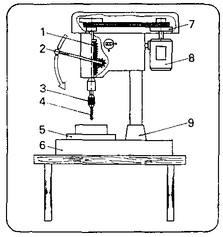
Figure 17.1

Figure 17.2
The instructor must not forget to mention the regulations on labour safety. It is also recommended to show protective devices of the machine (if available).
After having described the design and operation of the machines, the following drills have to be described;
- ‘hard’-type drills
- ‘normal’-type drills
- ‘soft’-type drills
- drills with carbide tips
- drills with double-taper drill point
- drills with flat drill point and centre point.
If the original tools cannot be shown, the illustrations contained in the “Trainnees’ Handbook of Lessons” will be sufficient to impart the necessary knowledge to the trainees.
Transparencies nos. 7.3. and 7.4. can also serve to give an illustrative description of “design and angles at the drill” and of types of drills as well as special kinds of drill point grinding.
The distinctions between the types of drills and their different fields of use have to be explained in detail.
The comprehensive hints contained in the “Trainees’ Handbook of Lessons” can support this instruction.
Subsequently, the trainees should answer the questions contained in the “Trainees’ Handbook of Lessons”.
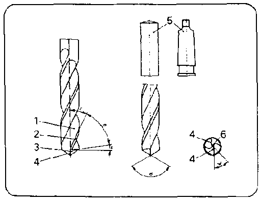
Figure
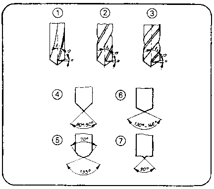
Figure
Action of drilling
The instructor describes the main movements of a drill and describes the interaction of feed and rotary movement during chip removal. He has also to comment on the reduction of friction. The trainees have to understand that permanent cooling extends the life of drills.
In this connection it is advisable to speak about the trends of development in the field of drill materials mentioned in the “Trainees’ Handbook of Lessons”.
Setting of tool values
The instructor has to describe in detail how to determine the correct values for adjusting the rotational speed, cutting speed and feed.
The rules and tables contained in the “Trainees’ Handbook of Lessons” need comprehensive explanation. This can be supported by transparencies or by illustrations on the blackboard.
The rules for automatic feeds are:
|
Low feed - with high rotational speeds and hard
materials |
The rules for rotational speeds are:
|
Low speed - with hard materials and large drill
diameters |
Table of rotational speeds (Gross Survey) at a cutting speed for drilling without automatic feed:
|
Material |
diameters of drills in mm (ranges) | |||||
|
|
1-3 |
3-5 |
5-8 |
8 -10 |
10 - 12 |
12 - 16 |
|
soft materials |
7100 |
5600 |
3500 |
2800 |
2200 |
1800 |
|
Al, Cu |
4500 |
3500 |
2200 |
1800 |
1400 |
1100 |
|
medium-hard steel |
2800 |
2200 |
1900 |
1100 |
900 |
710 |
|
cast steel hard materials |
1800 |
1400 |
900 |
700 |
560 |
450 |
|
Cr, Ni-alloys |
350 |
350 |
350 |
350 |
280 |
220 |
Rotational speed calculation

n = rotational speed in r.p.m.
v = cutting speed in m/min
d = diameter of drill in mm
p = 3.14
After having imparted this knowledge to the trainees exemplary calculations can support this instruction. It is recommended to ask the trainees to determine various rotational speeds. They must learn how to read the table values and how to set the machines accordingly.
Clamping of tools and workpieces
The instructor demonstrates the use of such tool clamping devices as e.g. “three-jaw chuck” and “taper-sleeve”.
The instruction comprises the description of the interactions of drill shank and tool clamping device.
Transparency no. 7.5. can illustrate the process of clamping a workpiece. Subsequently, all the clamping devices available in the workshop (machine vices, clamp dogs, clamps) should be described and their use explained.
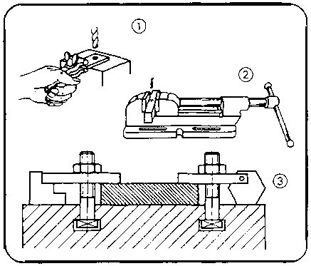
Figure 7.5
Technological sequence of drilling
9 steps of work are described in the “Trainees’ Handbook of Lessons” in order to produce a blind hole. These steps need comprehensive explanation. Such a instruction includes hints about possible errors and their effect on the hole.
Purpose and application of counterboring/countersinkinq
Available workpieces should be used to explain the purpose of counterboring/countersinking operations. Subsequently, the counterbores/countersinks and their different uses should be described:
- (pointed) countersink 60°, 75°, 90°- flat countersink
- three-lipped twist drill (spiral countersink)
- head counterbore or counterboring tool with pilot
- form counterbore or rotary files.
If these tools are not available, the illustrations contained in the “Trainees’ Handbook of Lessons” or transparency no. 7.6. can serve as a model.

Figure
7.6
3.2. Exercises
If it has not been possible to include the necessary demonstrations of drilling actions into the instructions, this shall be done immediately before the start of the practical exercises. After a short practice in setting the machines, the exercises of the “Instruction Examples for Practical Vocational Training” can be carried out,
However, it is necessary to prepare every individual exercise by a job-related instruction during which the trainees are shown a completed workpiece so as to demonstrate aim and object of the exercises.
|
The instructor must have made such a workpiece by himself in order to be familiar with all the problems which might arise in producing such a workpiece. |
The instructor can mention the criteria for evaluation as well as the problems involved. During these lessons of special instruction the sequences of operations and the working drawings of the training examples must be placed on the desks so that the trainees can make notes therein.
|
The trainees must not operate these drilling machines unless they had an instruction in the functions of the controls. |
It must be checked, whether the trainees have had such an instruction in labour safety regulations for drilling machines. (Check, whether there is an entry on labour safety instructions in the control book.) If this is not the case, the trainees must have such instructions right now!
When the trainees carry out these exercises, the instructor must always monitor their work. Special attention must be drawn to the drilling of holes, and you must not forget to check the clamping tightness.
It is advisable for the instructor to demonstrate again to all trainees the operation of the machine, the clamping of the workpiece and of the drill. Special attention must be drawn to the process of centring (alignment of holes and work-spindle), if the workpiece had been unclamped after the drilling and before the counterboring/countersinking stages. As it will not be possible to provide each trainee with a drilling machine, the instructor has to determine the proper succession in which the trainees will operate the machines. This is to be included into the instruction in the actual task (taken from the training examples).
|
During the exercise the instructor has to make sure that only one trainee operates the machine! Several trainees at one machine could distract each other from working and increase the risk of accidents. |
If waiting times occur, caused by using the machines during the exercises, these times should be bridged by performing some other subject-related work.
3.3. Examples for recapitulation and tests
This section comprises questions which are to consolidate and test the acquired skills and knowledge. Each question is accompanied by the respective answers to questions. Questions which are also contained in the “Trainees’ Handbook of Lessons” are marked with the letter “A”.
1. What is the purpose of drilling
(Production of straight
openings and holes.)
2. Name the types of drilling machines!
(Bench-type and
upright drilling machines and portable electric drills.)
3. Which types of drill designs do you know?
“A”
(The drill types are “hard” - “normal” - “soft”
drills with caribide tips.)
4. When do we use a “normal” type
drill?
“A” (When drilling in general structural steel, low-alloy
steel and cast iron.)
5. Name the main parts of a drill!
“A” (Chisel
edge, principal cutting edge, flanks, land, helical flute, shank.)
6. What are the disadvantages of chisel edges and how can we
overcome them?
“A” (They exert pressure and squeezing actions in
the hole and consume about 1/3 of the feed force - therefore, pre-drilling or a
lateral grinding of the chisel edge is recommended.)
7. What is the task of the helical flute?
(Removal of chips.)
8. Which forms of shanks do you know?
(Up to about 10 mm they
are straight, above 10 mm they are tapered.)
9. What is the point angle of “normal” type
drilling?
(116° - 118°).
10. Name appropriate kinds of drill points for drilling hard
materials!
“A” (Point angles from 80° to 90° or
double-taper drill points)
11. Name appropriate kinds of drill points for drilling soft
materials!
“A” (Point angles from 130° to 140° or flat
drill point with centre point.)
12. Where can we use drills with “flat drill point and
centre point”?
“A” (We use them for soft materials, thin sheet
metal and cylindrical counterborings.)
13. What is the correct rotational speed to be selected for
drilling a hole of 5 mm diameter in a workpiece of steel by means of a
bench-type drilling machine and hand feed (manual
feed)?
“A”(
tabular value =
1400 or 2240 r.p.m.)
14. What rules do we apply for selecting the rotational
speed?
(High rotational speed with small drill diameters and soft materials.)
15. Name clamping devices for
1. tools with straight shank
2. tools with tapered shank.
“A” (1. three-jaw chuck; 2. taper sleeve.)
16. Which kinds of clamping workpieces do we know?
(Clamp
dog, machine vice, drilling vee, clamping device for machine table.)
17. What is the sequence of operations of drilling a blind
hole?
(Scribing, prick-punching, spot-drilling, setting of depth, drilling up
to the stop, cleaning, checking.)
18. What do we have to take into account for
counterboring/countersinking?
“A” (Before
counterboring/countersinking operations can begin you must align the hole with
the work spindle. In order to avoid unclean surfaces you must employ low
rotational speeds.)
19. When do we use a 90 countersink?
“A”
(Spot-facing of holes which will be reamed or into which countersunk screws will
be fitted.)
20. When do we use form counterbores?
“A” (We need
them for deburring work and for completing irregular and curved
openings.)
4. Application of the working techniques of “Drilling, Countersinking and Counterboring”
The sequence of exercises can follow the variants mentioned in section 3. The subject can be dealt with comprehensively or subdivided into several stages.
The “Instruction Examples for Practical Vocational Training - Drilling, Countersinking and Counterboring” provide 6 exercises. These “Instruction Examples...” also comprise a list of required materials (initial material, working tools, measuring and testing tools, accessories) as well as the sequence of operations for the exercise and an illustrative working drawing, Thus, the trainees avail of all the information necessary for carrying out their exercises in a task-related way. If the quality of the produced workpieces is considered substandard, the trainee has to carry out comprehensive preliminary exercises. For this purpose, any waste parts may be used. If the respective skill has been practised sufficiently, the envisaged training workpiece can be produced. The following hint should be taken into consideration:
The trainee has to do all the work involved alone - from cutting the initial material to completing the workpiece.
This is the only way to guarantee a just evaluation of the achievements.
If the proposed “Instruction Examples” are not used for practical training, it will be possible to select other parts for practising. In this case, all the working techniques discussed earlier should be also practised on those parts.
4.1. Instruction examples
What follows is a brief description of the individual training examples in order to give a survey of the parts to be produced for practising the knowledge acquired:
Instruction example no. 7.1.
Drilling, countersinking and counterboring training workpiece
This is a component consisting of two clamped square steel bars.
Figure
Along the dividing line the trainee has to drill and counterbore/ countersink several holes. After this process, the two pieces can be separated again and the trainees can optically check the produced bore-hole walls.
Instruction example no. 7.2.
Clamping jaws for round material
Figure
Two pieces of flat steel with a spacer of thin steel sheet will be provided with simple through holes of small diameters. After their completion these clamping jaws can be used as accessories for clamping round materials (similar to vee jaws).
Instruction example no. 7.3.
Rivet set and rivet header
Silver steel round materials are provided with a hole and a counter-bore each in their centre. After their completion and hardening these parts can be used as tools for the working technique of riveting.
Figure
Instruction example no. 7.4.
Drill stand
Channel steel will be provided with small-size blind and through holes (increments of 1/10 mm). The parts produced as instruction examples 2.3. or 4.2. will be employed now.
Figure
After completion, the drill stand can serve as an easy to survey and practical support for drills in the workshop.
Instruction example no. 7.5.
Bottl-opener
Stainless steel plates serve to practise drilling of curved contours and drilling of several parts at a time.
After completion the trainees can use this bottle opener.
Figure
Instruction example 7.6.
Rotary head for threaded spindle
The trainees practise drilling on inclined surfaces of round steel provided with an inserted threaded spindle. As the drilling must be carried out on the lateral area of the cylindrical surface, the workpiece must be turned step by step during this process. This component can be combinde with the components of the instruction examples nos. 2.5., 8.2. and 9.5. to a C clamp.
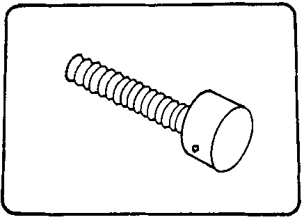
Figure
4.2. Criteria for practical training
It is recommended to determine some major points of observation and evaluation. The following criteria can serve as a guideline:
- Is the hole properly scribed and pre-punched?- Is the drill properly clamped?
- Did the trainee check whether there are grinding flaws on the drill?
- Does the trainee align the workpiece exactly and does he clamp it appropriately?
- Did the trainee protect the workpiece from being pulled up or distorted?
- Does the trainee select the proper rotational speed?
- Did the trainee think of protecting his head and eyes?
- Did the trainee find the correct drilling depth of planned blind hole s?
- Does the trainee use lubricants and coolants during drilling operations?
- Does the trainee properly check hole diameter and hole depth?
- Does the trainee centre the hole exactly below the counterbore/countersink?
- Does the trainee select the exact rotational speed for the counterbore/countersink?
- Does the trainee pay attention to the fact that the counter-bore/countersink must be pressed into the hole care-fully and sensitively?
- Does the trainee clean the hole properly?
5. Captions and legends of the “Drilling, Countersinking and Counterboring” transparencies series
|
Transparency no. 7.1. |
Bench-type drilling machine |
| |
1 drill spindle |
| |
2 hand lever for feed |
| |
3 drill chuck |
| |
4 drill |
| |
5 workpiece |
| |
6 machine table |
| |
7 cone-pulley transmission |
| |
8 motor |
| |
9 column |
|
Transparency no. 7.2. |
Upright drilling machine |
| |
1 spindle head |
| |
2 hand lever for feed |
| |
3 drill spindle |
| |
4 machine table |
| |
5 motor |
| |
6 drive head |
| |
7 machine column |
| |
8 column base |
|
Transparency no. 7.3. |
Design and angles at drills |
| |
1 helical flute |
| |
2 land |
| |
3 flank |
| |
4 principal cutting edge |
| |
5 shank |
| |
6 chisel edge |
| |
a clearance angle |
| |
b wedge angle |
| |
g rake angle |
| |
d point angle |
| |
z complementary angle of the chisel edge angle |
|
Transparency no. 7.4. |
Types of drills and special drill points |
| |
(1) “hard” type 1 = 10° |
| |
(2) “normal” type 1 = 25° |
| |
(3) “soft” type 1 = 35° |
| |
(4) Point angle 80° - 90° (small) |
| |
(5) double-taper drill point |
| |
(6) point angle 130° - 140° (large) |
| |
(7) flat drill point with centre point |
|
Transparency no. 7.5. |
Clamping of workpieces |
| |
(l) holding of flat, small workpieces in a hand vice |
| |
(2) securing of small parts in a machine vice |
| |
(3) securing of large workpieces on a machine table with holding clamps. |
|
Transparency no. 7.6. |
Types and use of counterbores/countersinks |
| |
(1) (pointed) countersink - for fitting of countersunk screws |
| |
(2) flat countersink - for screws on uneven surfaces |
| |
(3) three-lipped twist drill - for enlarging holes by minor dimensions |
|
|
(4) head counterbore or counterboring tool with pilot - for fitting of cylindrical cap screws |
| |
(5) form counterbore - for different forms |
|
| ||||||||||||||||||||||||||||||||||||||||||||||||||||||||||||||||||||||||||||||||||||||||||||||||||||||||||||
Manual Working of Material/Metal - Course: Manual working of metal. Methodical course-guide for instructors (Institut f�r Berufliche Entwicklung, 218 p.)
Manual Reaming
1. Objectives and contents of practical vocational training in the working technique of “Manual Reaming”
By concluding their training, the trainees shall have a good command of the working technique of “Manual Reaming”. Therefore, the following objectives have to be achieved:
Objectives
- Knowledge of purpose and application of the reaming technique.
- Proper command of reaming straight and tapered holes and capability of making pin-type connections.
- Capability of selecting the appropriate reamers and of using them appropriately.
- Capability of carrying out the necessary calculations and quality control independently.
The following contents have to be imparted to the trainees:
Contents
- Purpose of reaming
- Tools for reaming
- Design and action of reamers
- Technological process of reaming
- Special knowledge of straight and tapered fitting holes.
2. Organizational preparations
In order to guarantee a trouble-free development of the instructions, exercises and practical work it is necessary to prepare this training properly:
The following steps have to be taken:
2.1. Preparation for instructions on labour safety
Prior to the exercises a brief instruction on the proper use of tools and equipment has to be given. This comprises also hints for accident-free work.
The main points are similar to that of the working techniques of “Drilling, Countersinking and Counterboring”. The respective hints have to be repeated, and some supplementary points concerning the new working technique have to be added.
Supplementary points:
- Firm clamping of reamer in a tap wrench.
- Never turn a reamer in anticlockwise direction - risk of breakage!
- Use of lubricants and coolants during reaming processes.
- Put down reamers carefully and make sure that they cannot drop!
- Never leave the reamer in a hole when interrupting your work
Familiarity with these hints has to be confirmed by the trainees signatures in a control book.
2.2. Provision of the necessary teaching aids
For demonstration purposes during the instructions a vice should be installed at the place of instruction. The “Trainees’ Handbook of Lessons - Manual Reaming” is to be handed out to the trainees in sufficient numbers. When using the transparencies series of “Manual Reaming”, check whether they are complete (transparencies nos. 8.1. - 8.4.) and whether the overhead projector is functional. (Check the operating conditions at the place of instruction and make sure of the proper mains supply!) Surveys etc. which are to be written on the blackboard have to be completed prior to instruction.
All the tools and accessories for reaming mentioned in section 3 should be kept ready for illustration purposes.
2.3. Provision of working tools and materials
- Sufficient copies of the “Instruction Examples for Practical Vocational Training - Manual Reaming” must be handed out to the trainees to provide them with the theoretical foundations for the exercises to be carried out,
- The initial materials necessary for the exercises have to be prepared and laid out in sufficient numbers according to the materials mentioned in the “Instruction Examples...”- Each trainee is to be provided with a workbench at which a vice is firmly installed (check the proper height of this vice!).
- The trainees’ workbenches have to be fully equipped with tools and accessories according to the planned exercises.
Recommended basic equipment:
- steel rule, vernier caliper, external micrometer- steel scriber, marking gauge, centre punch
- locksmith’s hammer, aluminium hammer, hand hacksaw
- drills - countersinks 90, hand reamers (straight and tapered), rivet hole reamers.
- Bench - and column-type drilling machines and the necessary clamping devices (machine vices, holding clamps, C-clamps) must be provided for the necessary preliminary work (drilling and counterboring/countersinking).
- Prior to the start of the exercises, the drilling machines have to be checked for a good working order according to the points contained in the regulations on labour safety.
2.4. Time schedule
Time planning is recommended for the following training stages
- introduction to the working technique in the form of instructions
- necessary demonstrations
- calculations for the technological process to prepare the exercises
- job-related instructions to prepare the exercises
- carrying-out the exercises
- recapitulations and tests.
The necessary time share depends on the respective training conditions. The instructor has to bear in mind that waiting times will occur at the machines, if there are not enough drilling machines available. Such waiting times should be bridged by minor subject-related tasks.
3. Recommendations for practical vocational training in the working technique of “Manual Reaming”
The following paragraphs comprise proposals on conducting trainee instruction, demonstration of working techniques as well as exercises and tests.
Two course variants are offered:
Variant no. 1
This variant should be used for trainees with previous knowledge and generally good achievements and receptiveness:
1.1. Introductory instruction for the whole subject with demonstrations according to the “Trainees’ Handbook of Lessons”.1.2. Practice in reaming according to the “Instruction Examples nos. 8.1, - 8.5.” and subsequent evaluation.
1.3. Final test of theory knowledge according to the “Examples for recapitulation end tests”.
Variant no. 2
This variant should be used for trainees with only little previous knowledge or poor achievements:
2.1. Introductory instruction for the subject of “straight fitting holes” with demonstrations according to the “Trainees’ Handbook of Lessons”.2.2. Exercises on straight fitting holes according to the “Instruction examples 8.1. and 8.2.” and subsequent evaluation.
2.3. Supplementary instruction for the subject of “tapered fitting holes” according to the “Trainees’ Handbook of Lessons”
2.4. Exercises on tapered and straight fitting holes according to the “Instruction examples 8.3. - 8.5.” and subsequent evaluation.
2.5. Final test on theory knowledge according to the “Examples for recapitulation and tests" .
Practical knowledge and skill should be checked immediately after handing over the completed workpieces. Theory knowledge can be checked constantly, however, it is recommended to have a final written test (item 1.3. or, resp., 2.5.) after the exercises.
3.1. Introductory instruction
If possible, this instruction should be conducted in a classroom, Make sure that the trainees put down necessary and supplementary notes or answers to questions in their “Trainees’ Handbook of Lessons”.
The subject of instruction can follow the main points contained in the “Trainees’ Handbook of Lessons”. A good command of the working techniques of “Drilling, Countersinking and Counter-boring” is an essential prerequisite for learning the working technique of “Reaming”. When imparting knowledge to the trainees it is recommended to repeatedly refer to these working techniques. Instruction in the main subjects of “purpose of reaming; tools; design and action of reamers” is to be heavily supported by all those teaching aids available.
Purpose of reaming
To illustrate the purpose of reaming it is recommended to show to the trainees for comparison cut workpieces which are drilled or, resp., finished with reamers. It would be favourable to demonstrate examples of gears and shafts, machine taper connections and pin-type connections, if available. The findings should be summarised with the help of the descriptions contained in the “Trainees’ Handbook of Lessons”.
Tools, design and action of reamers Practice-related training can be continued based on main points contained in the “Trainees’ Handbook of Lessons”. In addition to the prepared original tools the transparencies nos. 8.1., 8.2. and 8.3. can be used as teaching aids.
The instructor has to give a detailed description of the use of the individual types of reamers so that the trainees will be in a position to conclude the use of a reamer from its design.
Figure 8.1
The following original reamers should be demonstrated:
- shell reamer
- adjustable reamer
- taper reamer (single and set)
- rivet hole reamer (structural reamer)
- straight hand reamer
- straight machine reamer
Figure 8.2
Tap wrench as well as containers for lubricants and coolants (with brush) should be shown as accessories.
The description of the cutting portion of straight hand reamers should be supported by showing machine reamers.
The comparison of the relationship of the cutting portions makes it easy to see and understand where to use these reamers. A demonstration of the action of reamers should be included in the instruction. As it is necessary to have a workbench with a vice for this purpose, the instructor has to check the local conditions in advance so that it will not be necessary to interrupt the instructions by a time-consuming change of place (classroom - workshop).
Figure 8.3
This demonstration has to be carefully prepared:
- A drilled and counterbored steel part must be clamped in the vice.- A straight hand reamer (nominal diameter 8 mm), clamped in a tap wrench, has to be placed close to the vice.
- A small container with cutting oil and a brush has to be placed there too.
The trainees should stand around the vice and the instructor has to see to it that everyone can see this process and that no trainee stands behind him. Now, the reaming demonstration can begin. The trainees must learn that reamers have to be turned clockwise (even when removing the reamer) and that a permanent supply of cutting oil is necessary. It must be made clear that reamers have to be removed from their holes from time to time in order to remove the chips with the bursh.
During this process the instructor has to explain why he handles the reamer in such a way.
The trainees must learn that reaming operations need extreme attention, calmness and experience in order to achieve the required precision.
The trainees, who have to achieve a good command of this skill, will take the instructor as an example. Thus, the example of the instructor becomes decisive for the trainees’ motivation.
After this demonstration the trainees go on working with their “Trainees’ Handbook of Lessons”. Now they should answer the questions in the sections of “design and action of reamers”. The trainees must have the change to put questions.
Technological process of reaming
The technology of this working technique has to be shown in detail and particularly distinctly. Therefore it will be necessary to explain the tables nos. 1, 2 and 3 (written on the blackboard).
Table no. 1 Technology of producing a fitting bore-hole
|
No. operation |
working tools, testing tools and accessories |
tool and machine values |
|
1 clamping |
vice, C-clamps |
- |
|
2 scribing and prick-punching |
steel scriber and prick-punch |
according to drawing |
|
3 drilling |
drill, vernier caliper, lubricant and coolant |
drill diameter, depth of hole, rotational speed |
|
4 counter -sinking |
90° - countersink vernier caliper |
countersink diameter rotational speed 350 r.p.m. |
|
5 reaming |
hand reamer tap wrench |
to fit tolerances |
|
6 cleaning |
compressed air or brush |
- |
|
7 testing |
limit plug gauge |
to fit tolerances |
|
In order to prepare a pin-type connection: | ||
|
7 pinning and testing |
cylindrical pin or tapered pin aluminium hammer |
length of pin |
Table no. 2 Empirical values for undersizes of holes in steel
|
N in mm |
U in mm |
|
up to 5 |
0.1 - 0.2 |
|
5-20 |
0.2 - 0.3 |
|
21 - 31 |
0.3 |
|
33 - 50 |
0.5 |
Table no. 3 Formulae for calculating the tool values for reaming
1. For drilling the hole:
|
D = N - U |
D = diameter of drill |
|
|
N = nominal diameter of a fitting hole |
|
|
U = undersize (empirical value) |
2. For counterboring/countersinking;
|
D = N + 0.2 mm s |
Ds = diameter of countersink/counterbore |
| |
N = nominal diameter of fitting bore holes |
Table no. 1 gives a detailed description of the work cycle.
The individual stages of work can be comprehensively described by using numerical examples.
It is recommended that the trainees do calculations at the blackboard using the data contained in the tables 2 and 3 or enter the values on the blackboard.
During the instructions the trainees should make notes in the margin of the “Trainees’ Handbook of Lessons”.
Testing of straight reamers, designations of fits on straight reamers
If it is quite clear that the exercises will be carried out by standardised reamers according to the “ISA system of tolerances and fits”, the respective sections should be taught on the basis of the “Trainees’ Handbook of Lessons”.
If this is not the case, the designations of reamers and limit plug gauges must be taught in another way.
To consolidate the knowledge acquired, the question in the “Trainees’ Handbook of Lessons” (table) can be answered.
If major problems occur, the instructor has to give and discuss further examples based on the tables.
The trainees must not begin with practical exercises until all the trainees have a good knowledge of this technology.
Special hints as to producing tapered fitting holes
The purpose of tapered connections has to be described once again. Illustrative objects (tools, finished connections with tapered pins, machine taper connections) as well as transparencies nos. 8.2. and 8.4. have to be employed appropriately. The use of rivet hole reamers, serial taper reamers and single taper reamers is to be described clearly. Special attention is to be drawn to single taper reamers for tapered-pin connections.
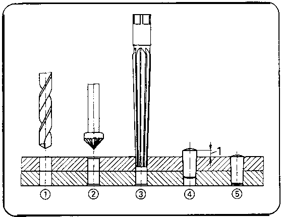
Figure
Table no. 4 and Figure no. 5 (on the blackboard) can serve to show the special features of the stages of this working process.
Table no. 4
Empirical values for prefitting of taper
pins with a taper ratio of 1:50
|
Nominal diameter of taper |
dimension for prefitting |
|
5 |
3 |
|
6 |
4 - 5 |
|
8 |
5 - 6 |
|
10 |
8 |
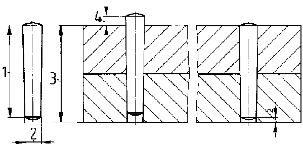
Figure
Conditions for fitting tapered pins:
1 length of tapered pin
2 nominal diameter of tapered pin
3 thickness of the components to be connected
4 dimension for pre-fitting
It is recommended to demonstrate how a taper pin connection can be made. Therefore, a workbench with vice must be available. However, the instructor has to check whether the local conditions make this possible or not. Otherwise the demonstration can be carried out after the instruction in a workshop. The demonstration is to be prepared as follows:
- Two steel parts mounted in a C-clamp and provided with drilled and countersunk hole when mounted together are to be clamped in a vice.- A taper reamer (fixed in a tap wrench) as well as a matching taper pin are to be placed close to the vice.
- A container with cutting oil and a brush as well as an aluminium hammer (or, a locksmith’s hammer) and a non-ferrous metal plug must also be placed close to the vice.
During the demonstration each operation of the instructor has to be described. The instructor has to stress again that the parts are drilled, counterbored and fixed in the vice while being clamped together.
Make sure that the C-clamp is fixed in such a way that it does not interfere with performing the work!
The instructor has to show the interaction of reaming and checking processus in order to achieve a precise pre-fitting result. The driving-in of the pin and the removal of the holding clamp give evidence that the pin holds both parts firmly together. This is the conclusion of the demonstration. Subsequently, the instructor has to demonstrate how such a connection can be detached by the appropriate non-ferrous metal plug. (Demonstration of separability of taper pin connections.) After this demonstration the trainees can answer the respective questions contained in the “Trainees’ Handbook of Lessons” and referring to the process observed before.
3.2. Exercises
If it has not been possible to include the demonstration of the action of reamers in the instructions, this should be done right now before the exercises in the workshop begin. If the trainees avail of little practical skill only, they should carry out some preliminary exercises on any steel parts:
- simple straight fitting holes
- small-size connections with cylindrical pins
- simple taper-pin connections of smaller diameters
- reaming of offset rivet holes.
However, it is also possible to begin with the first exercise immediately - based on the “Instruction examples for practical vocational training”.
However, it is necessary to prepare every individual exercise by a brief “job-related instruction”, during which the trainees are shown a finished workpiece in order to demonstrate the objectives and crucial points of this exercise.
|
The instructor must have finished such a workpiece himself in order to be familiar with all the problems which might arise in producing such a workpiece. |
Thus, the instructor is capable of mentioning the crucial points of evaluation as well as the difficult areas in manufacturing such a workpiece. During these instructions the sequences of operations and the working drawings should be placed on the desks so that the trainees can make notes therein.
|
The trainees must not operate the drilling machines before they are familiar with the function of the control elements. |
The instructor has to check whether the trainees had been given the instruction in operating drilling machines (based on the control book of labour safety instructions). If this is not the case, this must be done now. When giving his instruction the instructor must permanently monitor the trainees: No practice without supervision! Special attention is to be drawn to producing bore holes. It is recommended to check whether the objects are firmly held by the clamping devices.
It is advisable that the instructor demonstrates again the operation of the machine, the clamping of the workpiece and of the drill. Special emphasis is to be laid on the process of centring (alignment of bore hole and work spindle) if the workpiece had been unclamped between the stages of drilling, countersinking and counterboring.
As it will not be possible to provide each trainee with a drilling machine, the instructor has to determine the proper succession in which the trainees will operate the machines. This instruction must be job-related (based on the instruction example).
|
During the exercise the instructor has to make sure that only one trainee operates the machine. Several trainees at one machine could distract each other from working and increase the risk of accidents! |
If waiting times occur, caused by using the machines during the exercise, these times should be bridged by performing some other subject-related tasks.
3.3. Examples for recapitulation and tests
This section comprises questions which are to consolidate and check the previously acquired knowledge and skills. Each question is provided with the respective answer. Questions which are also contained in the “Trainees’ Handbook of Lessons” are marked with the letter “A”.
1. What is the purpose of reaming?
(Precise finishing of bore
holes, production of tapered and fitting bore holes, compensation for offset
rivet holes.)
2. What is the design of a straight hand reamer?
(Long
cutting portion - 1/4 of it is lead; shank with square)
3. Where do we find the nominal diameter on a taper
reamer?
(At the narrow end of the cutting portion)
4. What is the task of leads on straight hand
reamers?
“A” (The lead removes the biggest amount of chips.)
5. Why must a straight hand reamer have a relatively long
lead?
“A” (To ensure better guidance when starting.)
6. Why are relatively short leads on straight machine reamers
possible?
“A” (Because the precise guidance of the reamer is
guaranteed by the machine spindle.)
7. Why can we use the straight hand reamer for through holes
only?
“A” (Because of the long lead the blind hole would not be
reamed at the bottom of the hole.)
8. Why must we never turn a reamer in anticlockwise
direction?
“A” (Because the chips could jam behind the cutting
edges and cause a chipping of the cutting edges.)
9. Why is it necessary to draw out the reamers from the holes
from time to time?
(Because the chips have to be removed, otherwise the chips
would block the flute)
10. What is the effect of using straight-fluted reamers when
reaming a hole with feather keyway?
“A” (The straight cutting edges
collide with the edges of the feather keyway over the whole length, they are
overloaded and can break off.)
11. When do we use reamers with helical flutes?
(In bore
holes with recesses - such as feather keyways etc.)
12. Which steps are necessary for producing a fitting
hole?
(Clamping, scribing, prick-punching, drilling,
counterboring/countersinking, reaming, cleaning, testing.)
13. How can we calculate the drill diameter?
(Nominal
diameter minus undersize.)
14. What is the designation of a limit plug gauge for checking a
bore hole which was reamed with a f 8K7
reamer?
“A” (f 8K7 limit plug
gauge.)
15. Determine the following tool and machine values for
the
“A” production of a fitting straight through hole in steel with
a diameter of f 8K7:
|
diameter of drill: |
(D = 7.8 mm) |
|
rotational speed: |
(n » 1400 r.p.m.) |
|
counterbore diameter: |
(Ds = 8.2 mm) |
|
rotational speed for counterboring: |
(n » 350 r.p.m.) |
Supplement of tables in the “Trainees’ Handbook”: (machine vice; scriber, prick-punch; 90° countersink; brush; limit plug gauge f 8K7.)
16. How is prefitting for making a taper-pin connection
performed?
(Your thumb presses the taper pin into the bore hole. The pin must
protrude from the bore hole by a given measure.)
17. Why must we not hammer directly on the pin with the
locksmith’s hammer?
“A” (The pin is not hardened and it would
bend under the impact of the hammer.)
18. How can we separate pin connections?
“A” (We
place a non-ferrous metal plug mating the nominal diameter of the pin against
the opposite side on which the pin was driven in and begin with hammering on
it.)
19. The length of a taper pin is important for producing a taper
connection. What is to be taken into account when determining its
length?
“A” (It must be 2 mm shorter than the thickness of all
parts to be connected.)
20. Which basic principles of labour safety are to be
considered
“A” when performing reaming work?
|
(Selection: |
- fix the reamer firmly in the tap wrench |
| |
- never turn the reamers counterclockwise |
| |
- put down reamers carefully |
| |
- use lubricant and coolant for reaming.) |
4. Application of the working technique of “Manual Reaming”
Based on the variants described in section 3, the exercises can be designed as a single instruction or divided into two stages. Both variants envisage the production of the same complex workpiece on which the trainees can practise this working technique. Based on the “Instruction examples for practical vocational training - manual reaming”, five workpieces with gradually increasing degree of difficulty can be produced. These “Instruction Examples” also comprise a list of materials (initial materials, working tools, measuring and testing tools, accessories) as well as the sequence of operations for the manufacture of such a workpiece. Also contained is an illustrative working drawing.
Thus, the trainees avail of all the necessary information to begin their exercise-related work.
Due to the high degree of difficulty encountered in the working technique of “Manual Reaming” the selection of instruction examples was mainly restricted to the manufacture of fitting bore holes. Only the instruction examples 2 and 5 are objects which can be used and which are characterised by complex processes (acquisition of new working techniques and consolidation of previously acquired skills).
The following hint for organising the work should be taken into consideration:
|
The trainee has to do all the necessary work alone - from cutting the initial material up to the completion of the workpiece. |
This is the only way to guarantee a just evaluation of the achievements.
If the proposed “Instruction Examples...” are not used for the exercises, it will be also possible to select other workpieces. In this case all the working techniques acquired earlier should be also practised when working on these pieces.
4.1. Instruction examples
What follows is a brief description of the individual instruction examples in order to give a survey of the workpieces on which the previous knowledge can be employed:
Instruction example 8.1.
Training workpiece with straight fitting holes
This is a training workpiece consisting of two square steel bars clamped together to be provided with straight fitting holes on the dividing line of the square steel bars. After this process the two components can be separated again. The trainees will now have an optical impression of the precisely finished bore hole walls.
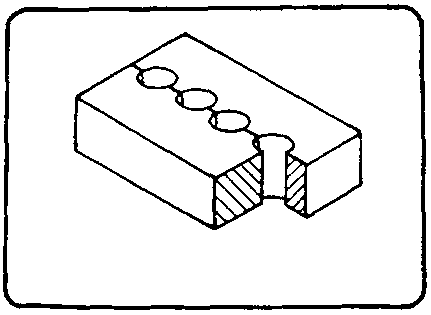
Figure
Instruction example 8.2.
Screw lock
This exercise serves to practise reaming processes for fitting cylindrical pins in a press-fit manner.
This part will be a component of a C-clamp which is to be completed by adding the components mentioned in the instruction examples 2.5., 7.6. and 9.5.
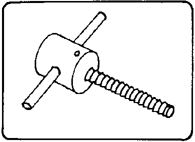
Figure
Instruction example 8.3.
Training workpiece with tapered fitting holes
This is a workpiece consisting of two square steel bars clamped together which are to be connected by means of taper pins. Fitting-in the taper pins is performed pin by pin so that the firm fit can be checked properly,
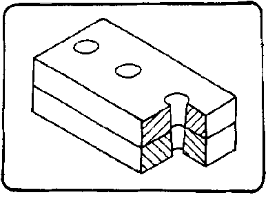
Figure
Instruction example 8.4.
Training workpiece for reaming rivet holes
Two metal sheets will be provided with bore holes and connected by means of a notched nail so that the bore holes are slighlty offset. The trainees are to practise the rivet hole reamer technique in order to ream bore holes in such a way that the appropriate rivets will fit.
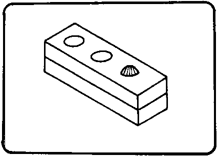
Figure
Instruction example 8.5.
Joint
This exercise serves to practise cylindrical and tapered pin connections. Combined press- and clearance-type fits serve to produce rigid and movable connections which function together.
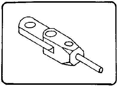
Figure
4.2. Criteria for practical training
It is recommended to determine some crucial points of evaluation and supervision. The following criteria can serve as a guideline
Operation no. 1 - clamping/fixing together
- Did the trainees select the appropriate clamping tool?- Did the trainees prepare a pin connection by means of clamps in such a way that the fixing of the components to be connected will last throughout all the working operations?
Operation no. 2 - scribing and prick-punching
- Is the marking precise?- Is the bore-hole centre sufficiently pre-punched?
Operation no. 3 - drilling
- Did the trainee choose the correct drill?- Is the drill properly chucked and is the correct rotational speed selected at the machine?
- Is a large-size tapered bore hole pre-drilled in steps (considering the taper ratio)?
- Does the bore-hole diameter comply with the specified size?
Operation no. 4 - counterboring/countersinking
- Did the trainee use the 90° countersink?- Did he set the correct rotational speed and were counterbore diameter and depth correct?
- Did the trainee countersink/counterbore both sides of a through hole properly?
Operation no. 5 - reaming
- Did the trainee choose the proper reamer?- Does the trainee use the reamer properly, i.e. perpendicular to the plane?
- Does the trainee always turn the reamer clockwise and exert a slight pressure from above?
- Does the trainee use lubricants?
- Does the trainee observe the principle of cleaning the reamer from time to time?
- Does the trainee interrupt the reaming process in order to perform the preliminary fitting for taper-pin fittings?
Operation no. 6 - cleaning of bore holes
- Does the trainee remove chips and oil residues after reaming or does he try to check the hole without cleaning it?
Operation no. 7 - checking and pinning
- Does the trainee choose the correct limit plug gauge and use it properly for checking cylindrical fits?- Does the trainee check both sides of a straight through hole?
- Does the trainee fix the pin appropriately i.e. using an aluminium hammer or locksmith’s hammer and a non-ferous metal plug?
- Do the pins fit well after pinning?
- Do the pin connections last after the removal of the clamps?
Prior to the start of the exercises the trainees should be made familiar with the main points of evaluating the exercises.
5. Captions and legends of the “Manual Reaming” transparencies series
Transparency no. 8.1. Straight reamers
(1) hand reamer - straight-fluted
(2) hand reamer - helical-fluted
(3) machine reamer - straight-fluted
(4) machine reamer - helical-fluted
(5) adjustable reamer
Transparency no. 8.2. Taper reamers
(1) taper reamer (ratio 1:50) - straight-fluted
(2) taper reamer (ratio 1:50) - helical-fluted
(3) rivet-hole reamer (ratio 1:10)
(4) serial taper reamers
4.1.- roughing reamer
4.2.- semi-finishing reamer
4.3.- finishing reamer
Transparency no. 8.3. Comparison of common reamers
(1) hand reamer (straight)
(2) machine reamer
(straight)
(3) taper reamer (ratio 1:50)
1. lead
2. cutting portion
3. neck
4. shank
5. square
6. nominal diameter
Transparency no. 8.4. Process of producing a taper-pin connection
(1) making a bore hole
(2) using a countersink of 90
(3) reaming with taper reamer
(4) pre-fitting of tapered pin
(5) proper pinning of tapered pin 1, pre-fit dimension.
|
| ||||||||||||||||||||||||||||||||||||||||||||||||||||||||||||||||||||||||||||||||||||||||||||||||||||||||||||||||||
Manual Working of Material/Metal - Course: Manual working of metal. Methodical course-guide for instructors (Institut f�r Berufliche Entwicklung, 218 p.)
Manual Thread Cutting
1. Objectives and contents of practical vocational training in the working technique of “Manual Thread Cutting”
By concluding their training, the trainees shall have a good command of the working technique of “Manual Thread Cutting”. Therefore, the following objectives are to be achieved:
Objectives
- Knowledge of purpose and application of the technique of manual thread cutting.- Proper command of internal and external threading operations and capability of producing bolted connections.
- Capability of selecting and properly using the appropriate tools.
- Capability of making calculations for the working process and of performing quality control independently.
The following contents must be imparted to the trainees:
Contents
- Purpose of thread cutting
- Thread-cutting tools
- Action of thread cutting
- Special hints for designating threads
- Technology of the internal and external thread-cutting operations.
2. Organizational preparations
In order to guarantee a trouble-free development of the instructions, exercises and practical work it is necessary to prepare this training properly.
The following steps have to be taken:
2.1. Preparations for instructions on labour safety
Prior to the exercises a brief instruction on the proper use of tools and equipment has to be given. This comprises hints for accident-free work too.
The main points of the working techniques of “Drilling and Counterboring/Countersinking” should be recapitulated and supplementary hints for the new working technique be given.
Supplementary hints:
- Clamp the tap firmly in the tap wrench.
- Clamp the threading die firmly in the die holder.
- Use lubricants and coolants.
- Prevent the tools from dropping and put them down carefully.
- Break the chips constantly during this process, otherwise you run the risk of tool breakage.
Familiarity with these hints has to be confirmed by the trainees signatures in a control book.
2.2. Provision of teaching aids
- For demonstration purposes during the instructions a vice should be firmly installed at the place of instruction.
- The “Trainees’ Handbook of Lessons - Manual Thread Cutting” is to be handed out to the trainees in sufficient numbers.
- When employing the “Manual Thread Cutting” transparencies series, check whether they are complete (transparencies nos. 9.1. - 9.4.) and whether the overhead projector is in working order. (Check the operating conditions at the place of instruction and make sure of the proper mains supply!)
- Surveys etc. which are to be written on the blackboard have to be completed prior to the instruction.
- All the tools and accessories mentioned in section 3 (for thread-cutting purposes) should be kept ready for illustration purposes.
2.3. Provision of working tools and materials
- The “Instruction Examples for Practical Vocational Training -Manual Thread Cutting” must be handed out to the trainees in sufficient numbers in order to provide them with the theoretical foundations of the exercises to be carried out.
- The initial materials necessary for the exercises have to be prepared and laid ‘out in sufficient numbers - based on the materials mentioned in the “Instruction Examples...”.
- Each trainee is to be provided with a workbench at which a vice is firmly installed. (Check the proper height of the vice!)
- The trainees’ workbenches have to be fully equipped with tools and accessories based on the envisaged exercises. Recommended basic equipment: steel rule, vernier caliper with depth gauge, try square, steel scriber, marking gauge, centre punch bastard and smooth files 200 mm (flat) hand hacksaw, locksmith’s hammer, aluminium hammer, flat chisel serial hand taps and nut taps M3 to M20 for right-hand thread limit plug gauges for threads M3 to M20 matching drills and countersinks dies M6 to M12 ring thread gauges M6 to M12
- Bench- or column-type drilling machines with the necessary clamping tools (machine vices, holding clamps, C clamps) are required for preparatory work, e.g. drilling and counterboring/countersinking operations.
- Before the exercises can be carried out, the drilling machines’ working order and compliance with the regulations on labour safety have to be checked.
2.4. Time schedule
Time planning is recommended for the following training stages
- introduction to the working technique in the form of instructions
- necessary demonstrations
- calculations for the technological process (preparation of exercises)
- job-related instructions to prepare the exercises
- carrying out the exercises
- recapitulations and tests.
The necessary time shares depend on the respective training conditions.
If waiting times occur at the machines (due to the fact that there are more trainees than machines) during practical work, these times can be bridged by minor tasks which are related to the subject.
3. Recommendations for practical vocational training in the working technique of “Manual Thread Cutting”
The following paragraphs comprise proposals on conducting trainee instructions, demonstrations of the working technique and the exercises as well as the tests.
Two course variants are recommended:
Variant no. 1
This variant should be chosen for trainees with previous knowledge and generally good achievements and receptiveness:
1.1. Introductory instruction for the whole subject accompanied by demonstrations which are based on the “Trainees’ Handbook of Lessons”.1.2. Exercises in producing internal and external threads based on the “Instruction Examples 9.1. - 9.6.” with subsequent evaluation.
1.3. Final test of theory knowledge based on the “Examples for recapitulation and tests”.
Variant no. 2
This variant should be chosen for trainees with little previous knowledge or poor achievements:
2.1. Introductory instruction for the subject of “internal thread cutting” (tapping) with demonstrations based on the “Trainees’ Handbook of Lessons”.2.2. Exercises in “internal thread cutting” (tapping) based on the “Instruction examples 9.1, - 9.3.” with subsequent evaluation.
2.3. Supplementary instruction for the subject of “external thread cutting” based on the “Trainees’ Handbook of Lessons”
2.4. Exercises in external and internal thread cutting operations based on the “Instruction examples 9.4. - 9.6.” with subsequent evaluation.
2.5. Final test of theory knowledge based on the “Examples for recapitulation and tests”.
Practical skills should be evaluated immediately after handing in the finished workpieces.
Theory knowledge should be constantly checked. However, it is recommended to have a final test written (item 1.3. or, resp., 2.5.) after concluding the exercises.
3.1. Introductory instruction
If possible, this instruction should be conducted in a classroom. Make sure that the trainees put down necessary supplementary notes or answers to questions in their “Trainees’ Handbook of Lessons”.
Instruction can be carried out on the basis of the main points contained in the “Trainees’ Handbook of Lessons”. In order to acquire the skills of the working technique of “thread cutting” the trainees must have a good command of the working techniques of “drilling and counterboring/countersinking”. This knowledge must be re-trained at an appropriate moment.
The subjects of “purpose of thread cutting, kinds of threads” as the description of the “tools for thread cutting” should be taught by employing all the teaching aids available.
Purpose of manual thread cutting
To demonstrate the purpose of thread cutting by hand it is advisable to show various examples of bolted connections, worn and torn bolts as well as cut workpieces (if available). This may serve to point out the single-piece nature of this working technique. The trainees have to understand that this technique is especially important for repair and maintenance work (when technical and economic reasons run counter to machine operation). The summary should be based on the “Trainees’ Handbook of Lessons”. The instructor has to give a survey of the types of threads. However, he has to restrict his description to fastening screw threads which are the only ones cut by hand. Here, the instructor should employ transparency no. 9.1.
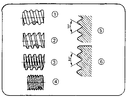
Figure 9.1
Thread-cutting tools
The instructor has to introduce the tools for internal and external thread cutting separately. It is recommended to demonstrate original tools mainly. However, transparency no. 9.2. can also be employed here.
The following original tools should be demonstrated:
- serial tap
- nut tap
- die with holder
- die-stock

Figure 9.2
Tap wrench as well as lubricant and coolant containers (with brush) are shown as accessories to the trainees. The description of the tool design must be structured in such a way that the trainees will understand the ranges of application immediately. To check the knowledge, the questions contained in the “Trainees’ Handbook of Lessons” should be answered subsequently. The trainee must be in a position to infer the use from the shape of the tools.
Action of thread cutting
A demonstration of the tools should be included into the instructions. As it is necessary to have a workbench with a vice for this purpose the instructor has to check the local conditions in advance in order not to interrupt the instructions by a time-consuming change of place (classroom - workshop). This demonstration has to be prepared carefully:
- A steel body with drilled and counterbored holes has to be clamped into the vice.- A nut tap (nominal diameter 8 mm) clamped in a tap wrench is to be placed close to the vice.
- A small container with cutting oil and a brush is also to be placed close to it.
The trainees should stand around the workbench in such a way that they can watch the process. None of them must be standing behind the instructor.
The trainees should carefully watch the process and not distract each other from concentrating on the demonstration. Subsequently, the instructor demonstrates the thread-cutting technique on an internal thread.
The instructor has to show the careful placing of the tool, the sensitive turning in up to the start of the cut and the subsequent permanent forward and backward movements which must be accompanied by a steady supply of lubricant and coolant.
|
The instructor has to explain to the trainees why he operates the tool in such a way. The trainees have to learn that thread-cutting operations need extreme attention, calmness and understanding. The more precisely the demonstration is carried out, the more the role of the instructor will grow in the eyes of the trainees. |
Having completed this demonstration, the instructor has to decide whether he will demonstrate the operation of external thread-cutting now or later.
The next stage is to discuss the main points of action contained in the “Trainees’ Handbook of Lessons” to recapitulate what the trainees have seen during the demonstration. The respective questions in the “Trainees’ Handbook...” can then be answered.
Special hints for the designation of threads
Based on the range of threads employed at the workplace the instructor has to comment on these designations. The “Trainees’ Handbook of Lessons” gives the example of “metric ISO threads” to show the connection between coarse and fine threads on the one hand and between the necessary cutting tools and testing tools on the other hand.
A similar form of instruction can be chosen to describe Whitworth and/or other kinds of threads. To check the trainees’ knowledge they have to answer the questions contained in their “Trainees’ Handbook of Lessons”.
Technology of internal thread cutting (tapping)
The “Trainees’ Handbook of Lessons” contains a very comprehensive description of the individual operations. Optically, this can be supported by employing transparency no. 9.5.

Figure 9.3
It will be necessary to put the tables nos. 1, 2 and 3 on
the blackboard in order to have a detailed discussion of the individual steps of
internal thread cutting operations. These tables contain data and information
which can be used in numerical examples.
Table no. 1
Table no. 2
Table no. 3
Table no. 1
Technological process of producing an
internal thread
|
no. operation |
working tools, measuring tools and accessories |
tool and machine values |
|
1 clamping |
vice, C clamps |
- |
|
2 scribing and prick-punching |
steel scriber, prick-punch |
as per drawing |
|
3 drilling |
drill, vernier caliper lubricant and coolant |
drill diameter, depth of bore hole; rotational speed |
|
4 countersinking |
60 countersink vernier caliper |
countersink diameter, rotational speed |
|
5 thread cutting |
serial or nut tap; tap wrench lubricant and coolant |
as per nominal dimensions |
|
6 cleaning |
compressed air or brush |
- |
|
7 testing |
limit plug gauge |
as per nominal dimensions |
Table no. 2
Pitch and tap runout depth with metric
coarse threads
|
N = nominal |
S = pitch/mm |
TA = tap runout depth/mm |
|
3 |
0.5 |
2.8 |
|
4 |
0.7 |
3.4 |
|
5 |
0.8 |
3.6 |
|
6 |
1 |
4.5 |
|
8 |
1.25 |
5 |
|
10 |
1.5 |
5.5 |
|
12 |
1.75 |
6 |
|
16 |
2 |
6.5 |
|
20 |
2.5 |
7.5 |
|
24 |
3 |
8.5 |
Table no. 3
Formulae for calculating the tool values (internal thread cutting)
1. Making the hole:
|
D = N - S |
TB = TG + TA |
|
D - drill diameter |
TB - depth of hole |
|
N - nominal diameter |
TG - depth of thread of thread |
|
S - pitch |
TA - runout depth |
2. Making a counterbored/countersunk hole:
|
Ds = N |
Ds = diameter of counterbored/countersunk hole |
|
|
N = nominal thread diameter |
Table no. 1 gives a clear and comprehensive description of the working process. Numerical examples will help to illustrate the individual activities.
Based on the tables nos. 2 and 3 and the figures 4-6 the necessary calculations can be made.
dimensions of internal threads
1 nominal diameter (N)
2 minor diameter (D)
3 pitch (P)
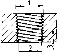
Figure
depths on internal threads
1 depth of hole (dh)
2 depth of thread (dth)
3 runout depth (ds)
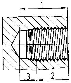
Figure
counterboring/countersinking of internal thread
1 diameter of counterbored/countersunk hole (Ds)
2 minor diameter (D)
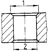
Figure
It is recommended that the trainees do some calculations on the blackboard where they should enter the calculated values in the formulae. In case of mistakes the instructor is in a position to correct them immediately. The respective question contained in the “Trainees’ Handbook of Lessons” must be answered by the trainees independently. Practical exercises should not be started before the trainees have a good knowledge of the technological process.
Technology of external thread cutting.
The instruction should be based on the main points contained in the “Trainees’ Handbook of Lessons” and supplemented by transparency no. 9.4.
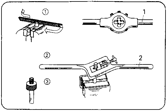
Figure 9.4
A demonstration has to be included now:
- A steel bolt (nominal diameter 8 mm) is to be clamped with appropriate accessories (vee jaws, vee attachments) in a vice.- The appropriate die, a file and container with lubricant/coolant and brush are to be placed close to the vice.
This demonstration is similar to the first one, i.e. all the activities need a comprehensive explanation.
The chamfering operation needs special attention, because a bad start of the cut (due to a bad chamfer) would render a continuation of cutting useless.
After the completion of this process each of the trainees has to hold such a cut thread in his hand and to look for faults.
|
Even a badly cut thread can serve as a teaching aid, if the instructor clearly indicates the faults and their causes. |
In addition to such an “optical inspection”, the hints contained in the “Trainees’ Handbook of Lessons” may serve as a teaching aid.
3.2. Exercises
If it has not been possible to include the demonstration of the action of external and internal thread-cutting tools in the instructions, this should be done right now before the workshop exercises begin.
If the trainees avail of little practical skill only, they should carry out some preliminary exercises at any steel parts:
Cutting of
- simple threaded through holes
- short external threads on bolts.
However, it is also possible to begin with the first simple exercises immediately - based on the “Instruction examples for practical vocational training”.
But it is necessary to prepare every individual exercise by a brief job-related instruction during which the trainees are shown a finished workpiece, in order to demonstrate the objectives and main points of this exercise.
The instructor must have finished such a workpiece by himself in order to be familiar with all the problems which might arise in producing such a workpiece.
Thus, the instructor can mention the crucial points of evaluation as well as the difficult areas of manufacturing such a workpiece. During these instructions the sequences of operations and the working drawings of the instruction examples should be placed on the desks so that the trainees can make notes therein.
The trainees must not operate the drilling machines unless they have been made familiar with the function of the control elements before!
The instructor has to check whether the trainees had been given such an instruction in operating drilling machines (based on the respective entries in the control book of labour safety instructions). If this is not the case, such an instruction has to be given now.
During the exercises the instructor must permanently supervise the trainees - no practice without supervision! Special attention must be drawn to the production of bore holes. The instructor is recommended to check the clamping tools for firm clamping.
It is advisable that the instructor demonstrates again the operation of the machine, the clamping of the workpiece and the proper drilling process. Special emphasis is to be laid on the process of centring (alignment of bore hole and work spindle) if the workpiece was unclamped between the stages of drilling and counterboring/countersinking.
As it will not be possible to provide each trainee with a drilling machine, the instructor has to determine the proper succession in which the trainees will operate the machines during this job-related instruction.
In this exercise the instructor has to make sure that only one trainee operates the machine. Several trainees at one machine could distract each other from working and increase the risk of accidents!
If waiting times occur during the exercises, caused by using the machines, these times should be bridged by performing some other subject-related tasks.
In this case the trainees can prepare the workpieces for the subsequent process of external thread cutting (sawing-off of bolts, chamfering of bolt heads).
3.3. Examples for recapitulation and tests
This section comprises questions which are to consolidate and test the previously acquired knowledge and skills. Each question is provided with the respective answer. Questions which are also contained in the “Trainees’ Handbook of Lessons” are marked with the letter “A”.
1. What is the purpose of manual thread cutting?
(Cutting of
helical turns of thread in tapping-size holes or on bolts in order to provide
bolted connections; manual thread cutting is mainly employed in the fields of
single-piece production and repair work, i.e. in fields where the use of
machines would be too expensive.)
2. What can be the purpose of screw-thread
connections?
(Fastening, movable connections, sealing connections, pipe
connections.)
3. Which kinds of thread are cut by hand?
(Fastening bolt
threads - e.g. metric and Whitworth threads; pipe threads - e.g. Whitworth pipe
threads.)
4. Which tools are used for cutting internal and external
threads by hand?
(Serial and nut taps; threading dies and die-stocks.)
5. How do the applications of serial and nut taps
differ?
“A” (Serial taps used for blind holes; nut taps used for
short through holes.)
6. How do the applications of threading dies and die-stocks
differ?
“A” (Dies are used for diameters of up to 12 mm; die-stocks
are used for diameters exceeding 12 mm.)
7. What kind of movement is involved in the process of thread
cutting?
“A” (Continuous forward and backward movement.)
8. Why must we always move taps or, resp., dies or die-stocks
backwards?
“A” (To break off the chips in the thread grooves.)
9. Why must we use lubricating and cooling
agents?
“A” (To reduce friction at the cutting edges, to protect
the tool from excessive heat, and to make the cutting process more smooth.)
10. What is the designation of a thread limit plug gauge which
is used for checking a hole cut with an M8 nut tap?
“A” (M8 thread
limit plug gauge.)
11. What does the designation “M 6 x 0.5”
mean?
“A” (Metric thread with a nominal diameter of 6 mm and a
pitch of 0.5 mm - fine pitch thread).
12. Which operations are involved in manufacturing an internal
thread?
(Clamping, scribing/prick-punching, drilling,
counterboring/countersinking, thread-cutting, cleaning of hole, testing.)
13. How can we calculate the minor diameter of an internal
thread?
“A” (Nominal diameter minus pitch.)
14. How do we have to consider the chamfer (pointing) of a tap
when determining the depth of a bore hole?
“A” (It has to be added
to the given depth of thread.)
15. How must tapping-size holes be countersunk?
(Through
holes must be countersunk on both sides with a 60° countersink to the
nominal diameter.)
16. Which testing tools are used to test a completely tapped
hole?
(Vernier caliper for depth measurement, thread limit plug gauge, for
true-to-size testing.)
17. Determine the following tool and machine values for producing a 15 mm deep internal thread M 10 in a steel part made of general structural steel:
|
drill diameter: |
(D = 8.5 mm) |
|
rotational speed: |
(n = 1100 r.p.m.) |
|
depth of hole: |
(TB = 20.5 mm) |
|
diameter of counterbored/ countersunk hole: |
(Ds = 10 mm) |
|
rotational speed for counterboring/ countersinking: |
(n = 350 r.p.m.) |
Supplement of table in “Trainees’ Handbook”:
“A” (machine vice; scriber/punch; 60° countersink; serial tap M 10; tap wrench, cutting oil; brush; thread limit plug gauge M 10)
18. Which operations are necessary to produce an external
thread?
(Clamping, chamfering, thread cutting, cleaning, testing.)
19. How do we fix bolts in a vice?
“A” (By means of
vee attachments, insets, vee jaws or clamping jaws for round material.)
20. Why must a bolt be provided with a chamfer?
“A”
(Otherwise it would be impossible to use the tool in an angular position.)
21. What kinds of faults on external threads can we detect by
eyesight?
(Oblique thread, rough and cracky
turns.)
4. Application of the working technique of “Manual Thread Cutting”
Based on the variants described in section 3, the exercises can be designed as a single subject-oriented instruction or divided into two stages. Both variants envisage the production of the same complex workpieces on which the trainees can practice this working technique. Based on the “Instruction examples for practical vocational training - Manual thread cutting”, six workpieces can be produced with a gradually increasing degree of difficulty. These “Instruction examples...” also comprise a list of materials (initial material, hand tools, measuring and testing tools, accessories) as well as the sequence of operations associated with the production of the workpiece. Also contained is an illustrative working drawing.
Thus, the trainees avail of all the necessary information to begin their exercise-related work.
The training examples are of a complex nature: the trainees will acquire new working techniques and consolidate skills acquired in the past.
If the course of the exercises shows that the achieved quality of the workpieces is not sufficient, the trainees have to perform more comprehensive preliminary exercises.
In this case it is possible to use any waste parts to practise the skills. The envisaged complex exercise can only begin when the respective skill has been practised sufficiently.
The following hint should be taken into account:
|
The trainee has to do all the necessary work alone - from cutting the initial material up to the completion of the workpiece. |
This is the only way to guarantee a just evaluation of the trainees’ achievements.
If the proposed “Instruction Examples...” are not used for the exercises, it will be also possible to select any other workpiece In this case care should be taken that all the working techniques acquired earlier in the field of thread cutting will be also practised when working on these pieces.
4.1. Instruction examples
What follows is a brief description of the individual instruction examples, in order to give a survey of the workpieces on which the previous knowledge can be practised:
Instruction example 9.1.
Training workpiece for internal thread cutting
This is a workpiece of two square steel bars clamped together and into which the trainee has to tap through and blind holes on the dividing line of the square steels. After this process both parts can be separated again. The trainee can now get an optical impression of the tapped holes.
Figure
Instruction example 9.2.
Thread holding clamp
This serves to clamp threaded bolts or screws for further processing in a vice. Metric coarse threads M3 to M10 will be produced in short through holes.
Figure
Instruction example 9.3.
Clamping jaws for threaded bolt
This also serves to clamp bolts or screws. However, M12, M16 and M20 threads will be produced now.
Figure
Instruction example 9.4.
Stone bolt
A short thread is to be cut on a bolt. This part can serve as a mounting component for wall installations.
Figure
Instruction example 9.5.
Threaded bushes and threaded bolts for C-clamp
The trainee has to produce central and precisely aligned tapped holes in round material as well as a mating long external thread on a bolt. These components are parts of a C-clamp which has to be completed by adding the components as per instruction examples 2.5., 7.6. and 8.2.
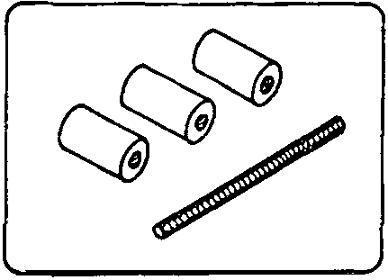
Figure
Instruction example 9.6.
Rope turnbuckle
The trainee has to produce an internal thread in combination with two mating external threads. This component can be used as a connecting and tightening component of rope systems.
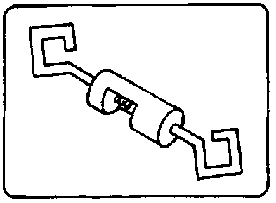
Figure
4.2. Criteria for practical training
It is recommended to determine some crucial points of evaluation and supervision. The following criteria can serve as a guideline
Cutting of internal threads
Operation no. 1 - clamping
- Did the trainee select the appropriate clamping tool?- Are the workpieces firmly fixed and protected from being pulled up or twisted on the machine table?
Operation no. 2 - scribing and prick-punching
- Is the marking precise?- Is the hole centre sufficiently pre-punched?
Operation no. 3 - drilling
- Did the trainee select the correct drill?- Is the drill properly chucked and is the machine set to the correct rotational speed?
- Is the punch mark precisely aligned with the drill?
- Did the trainee use lubricant and coolant during the drilling process?
- Does the drilled hole diameter comply with the given values?
Operation no. 4 - counterboring/countersinking
- Did the trainee use the 60 countersink?- Did he set the correct rotational speed, and is the diameter of the countersunk hole correct?
- Did the trainee countersink both sides of a through hole properly?
Operation no. 5 - thread cutting
- Did the trainee select the proper tap?- Does the trainee use the tap properly?
- Are the forward and backward movements in compliance with the requirements?
- Does the trainee use lubricant and coolant?
Operation no. 6 - cleaning of holes
- Does the trainee clean the hole or does he try to test the hole without cleaning it?
Operation no. 7 - testing
- Did the trainee select the proper thread limit plug gauge and did he employ it correctly?
Cutting of external threads
Operation no. 1 - clamping
- Did the trainee clamp the bolt appropriately in the vice ‘ (using the proper accessories)?
Operation no. 2 - chamfering
- Is the chamfer even and wide enough?
Operation no. 3 - thread cutting
- Did the trainee choose the proper cutting tool?- Is the die correctly inserted into the die holder?
- Is the movement of the die-stock correct, i.e. a movement from bottom to top?
- Is the rotary movement evenly smooth?
- Does the trainee use lubricant and coolant?
Operation no. 4 - testing
- Does the trainee choose the proper measuring and testing tools for checking the quality of the workpiece (ring thread gauge, vernier caliper)?- Is the trainee capable of evaluating the surface quality of the thread by eyesight?
Prior to the start of the exercises the trainees should be made familiar with the main points of evaluation.
5. Captions and legends of the “Manual Thread Cutting” transparencies series
|
Transparency no. 9.1.: |
Kinds of threads | |
| |
(1) round thread (knuckle thread) | |
| |
(2) saw-tooth thread | |
| |
(3) acme thread | |
| |
(4) V-shaped thread | |
| |
(5) Whitworth thread | |
| |
(6) metric ISO thread | |
|
Transparency no .9.2.: |
Serial taps | |
| |
(1) taper tap (No. 1 tap) | |
| |
(2) plug tap (No. 2 tap) | |
| |
(3) finishing tap (No. 3 tap) | |
| |
(4) comparison of length and angle of chamfer | |
| | |
1 - chamfer length |
|
Transparency no. 9.3.: |
Operations associated with internal thread cutting |
|
| |
(1) drilling of tapping-size hole | |
| |
(2) counterboring/countersinking of hole | |
| |
(3) roughing out | |
| |
(4) re-cutting with plug tap | |
| |
(5) finishing | |
|
Transparency no. 9.4.: |
Operations associated with external thread cutting |
|
| |
(1) chamfering of bolt with flat file | |
| |
(2) thread cutting with | |
| | |
1 - die and holder or |
| | |
2 - die-stock |
| |
(3) testing with ring thread gauge | |