Surface Water Treatment by Roughing Filters - A Design, Construction and Operation Manual (SANDEC - SKAT, 1996, 180 p.)
Contents — 9 sections
- Section 1
- Section 2
- Publishers
- Foreword
- Preface
- Executive summary
- Surface Water Treatment by Roughing Filters - A Design, Construction and Operation Manual (SANDEC -
- Surface Water Treatment by Roughing Filters - A Design, Construction and Operation Manual (SANDEC -
- Surface Water Treatment by Roughing Filters - A Design, Construction and Operation Manual (SANDEC -
 | | | Surface Water Treatment by Roughing Filters - A Design, Construction and Operation Manual (SANDEC - SKAT, 1996, 180 p.) | | | (introduction...) | | | Publishers | | | Foreword | | | Preface | | | Executive summary | | | Part 1: General aspects of roughing filter application | | | 1. Historical development and experience with water treatment | | | 2. Water treatment concept | | | 3. Raw water quality | | | 3.1 Raw water characterisation | | | 3.2 Catchment area | | | 3.3 Water quality analysis | | | 4. Solid matter separation | | | (introduction...) | | | 4.1 Sedimentation | | | 4.2 Roughing filtration | | | 5. Bacteriological water quality improvement | | | (introduction...) | | | 5.1 Slow sand filtration | | | 5.2 Chlorination | | | 6. Layout of a water supply scheme | | | 6.1 General considerations | | | 6.2 Hydraulic profile | | | 6.3 Treatment steps | | | 6.4 Water distribution | | | 7. Roughing filtration application | | | 7.1 Historic use | | | 7.2 Development of roughing filters | | | Part 2: Design, construction and operation of roughing filters | | | 8. Classification of roughing filters | | | 9. General aspects of roughing filter design | | | 9.1 Main features | | | 9.2 Basic filtration theory | | | 9.3 Design variables and guidelines | | | 9.4 Flow and headloss control | | | 9.5 Filter drainage system | | | 9.6 General design aspects | | | 10. Detailed filter design | | | 10.1 Intake Filters | | | 10.2 Dynamic filters | | | 10.3 Vertical-flow roughing filters | | | 10.4 Horizontal-flow roughing filters | | | 11. Roughing filter efficiency | | | 11.1 Practical experience | | | 11.2 Pilot plant tests | | | 12. Selection criteria for roughing filters | | | (introduction...) | | | 12.1 Raw water quality as selection criteria | | | 12.2 Layout and operational aspects as selection criteria | | | 13. Construction of roughing filters | | | (introduction...) | | | 13.1 Filter box | | | 13.2 Filter material | | | 13.3 Inlet and outlet structures | | | 13.4 Drainage system | | | 13.5 Gravel and sand washing facilities | | | 14. Operation and maintenance of roughing filters | | | (introduction...) | | | 14.1 Caretaker training | | | 14.2 Treatment plant commissioning | | | 14.3 Flow control | | | 14.4 Water quality control | | | 14.5 Filter cleaning | | | 14.6 Filter maintenance | | | 15. Economic aspects | | | (introduction...) | | | 15.1 Construction costs | | | 15.2 Operating and maintenance costs | | | 15.3 Overall costs of water supply schemes | | | 16. Design examples | | | (introduction...) | | | 16.1. Treatment of an upland river | | | 16.2 Treatment of a lowland stream | | | 16.3 Treatment of reservoir water | | | 16.4 Rehabilitation of a slow sand filter plant | | | 16.5 Standard designs for compact water treatment plants | | | 17. Final remarks | | | (introduction...) | | | References | | | Abbreviations | | | Annexes | | | Simple methods for water quality analysis | | | Simple methods for discharge measurements | | | Salient data and features of slow sand filters | | | Roughing filter theory | | | Pilot plant design examples | | | Roughing filter design examples | | | Outline for caretaker training | | | Monitoring of filter operation | | | Acknowledgements and credits |
|
| | | Surface Water Treatment by Roughing Filters - A Design, Construction and Operation Manual (SANDEC - SKAT, 1996, 180 p.) | | | (introduction...) | | | Publishers | | | Foreword | | | Preface | | | Executive summary | | | Part 1: General aspects of roughing filter application | | | Part 2: Design, construction and operation of roughing filters | | | Annexes |
|
by Martin Wegelin
SANDEC
Duebendorf, October 1996
This publication presents the concept, design and field
experience of roughing filters applied as pretreatment prior to slow sand
filters. It describes treatment and purification processes which convert turbid
surface water into safe drinking water. The presented treatment methods are
simple, efficient and reliable and, therefore, appropriate for rural water
supply schemes.
Surface water treatment generally requires at least two
treatment steps. The first step, also called pretreatment, concentrates mainly
on the removal of solids. Prefiltration by roughing filters is a simple and
efficient process for solid matter separation. However, roughing filters also
contribute to a bacteriological water quality improvement. The second step,
commonly considered as main treatment, is applied especially to remove or
destroy the remaining microorganism by slow sand filtration and chlorination.
This manual mainly focuses on the design, construction and
operation or prefilters and roughing filters. It is recommended as textbook for
teachers and students, as design manual for engineers and as operation and
maintenance guidelines for technicians. The manual draws its valuable
information from a vast field experience documented by the small stories
scattered throughout the
text.
| | | Surface Water Treatment by Roughing Filters - A Design, Construction and Operation Manual (SANDEC - SKAT, 1996, 180 p.) | | | (introduction...) | | | Publishers | | | Foreword | | | Preface | | | Executive summary | | | Part 1: General aspects of roughing filter application | | | Part 2: Design, construction and operation of roughing filters | | | Annexes |
|
Publishers
|
Text Revisors: |
Sylvie Peter |
|
Brian Clarke |
|
Script Processing: |
Brigitte Hauser |
|
Illustrations: |
Heidi Bolliger |
|
Lydia Zweifel |
|
Wey Photo Atelier |
Copyright © by SANDEC (Water & Sanitation in Developing
Countries) at EAWAG (Swiss Federal Institute for Environmental Science and
Technology), CH-8600 Duebendorf, Switzerland.
Permission is granted for reproduction of this material, in
whole or part, for education, scientific or development related purposes except
those involving commercial sale, provided that
- full citation of the source is given
- written request is
submitted to SANDEC
ISBN: 3-908001 -67-6
Publisher: Swiss Centre for Development Cooperation in
Technology and Management (SKAT), CH-9000 St. Gallen, Switzerland
Distributor: Intermediate Technology Publications (it),
103-105 Southampton Row, London WC1B 4HH, England E-mail: itpubs@gn.apc.org;
Fax.: +44-171 -436 2013

SANDEC
SANDEC's Roughing Filter Project was substantially cofinanced by
the Swiss Agency for Development and Cooperation
(SDC)
| | | Surface Water Treatment by Roughing Filters - A Design, Construction and Operation Manual (SANDEC - SKAT, 1996, 180 p.) | | | (introduction...) | | | Publishers | | | Foreword | | | Preface | | | Executive summary | | | Part 1: General aspects of roughing filter application | | | Part 2: Design, construction and operation of roughing filters | | | Annexes |
|
Foreword
SANDEC, the Department for Water and Sanitation in
Developing Countries (formerly IRCWD) at EAWAG, has been involved
in the development and promotion of roughing filters for over a decade.
Horizontal-flow roughing filtration was originally studied in the laboratory,
then field tested by our cooperation partners in developing countries and
finally implemented in demonstration projects. A manual containing a description
of this treatment process was published in 1986 as IRCWD Report No. 06/86.
However, the roughing filter technology continued to be
developed in the following years, and different types of prefilters and roughing
filters were studied and tested. Some of the field staff, not aware of this
development, continued to apply exclusively horizontal-flow roughing filters
also in places where other filter types would have been more appropriate.
This new manual has been compiled to bridge this information
gap. It is based on a complete revision of the old manual, on a draft presented
at the International Conference on Roughing Filtration held in Zurich,
Switzerland, in June 1992 and on SANDEC's field experience in the implementation
of roughing filters. This manual received valuable information from our
cooperation partners in developing countries.
SANDEC is grateful for the collaboration and support provided by
all the institutions and persons involved in this project. I should like to
express my gratitude to the Swiss Development Cooperation, particularly to
Messrs Armon Hartmann and Paul Peter who have strongly supported EAWAG's
roughing filter project. Last but not least, I extend my thanks to the reviewers
of this manual for their valuable comments.
Duebendorf, October 1996
Roland Schertenleib
Director
SANDEC
| | | Surface Water Treatment by Roughing Filters - A Design, Construction and Operation Manual (SANDEC - SKAT, 1996, 180 p.) | | | (introduction...) | | | Publishers | | | Foreword | | | Preface | | | Executive summary | | | Part 1: General aspects of roughing filter application | | | Part 2: Design, construction and operation of roughing filters | | | Annexes |
|
Preface
This publication, which is divided into two parts,
presents water treatment alternatives particularly applicable to rural water
supplies in developing and newly industrialised countries, and describes
processes for solid matter separation.
|
Part 1 |
contains a general introduction to the subject of rural water
treatment. It describes the water treatment concept and raw water quality of
different types of surface water, summarises the various water treatment
processes used for solid matter separation, gives a brief account of
bacteriological water quality improvement, provides a general layout of water
supply schemes, and presents the development of roughing filter application
|
|
Part 2 |
elucidates design, construction and operation characteristics
of different prefilters and roughing filters. It provides comprehensive
information on filter layout, presents practical experience with different
filters, describes selection criteria and procedure for adequate treatment plant
design, discusses construction, operational and economic aspects, illustrates
some design examples, and discloses valuable information on the practical
implementation of the prefiltration technology. |
Part 1 thus focuses on general aspects of rural water treatment
and allows the interested reader to get a glimpse of the different challenges
posed by the water treatment technologies. In Part 2, the reader will get a
comprehensive view of the pretreatment processes applied to solid matter
separation and a detailed description of the application of this technology.
This publication may be used as general textbook by
teachers interested in rural water treatment technologies, by engineers
who have to select and design appropriate treatment installations, and by
operation and maintenance technicians who have to train treatment plant
operators.
A technical publication is rather rational and dry. However,
efforts have been made to formulate and illustrate this manual in a lively,
easily understandable and attractive manner. Unexpected problems and challenges
are often encountered with filter design, construction and operation. The
"hardware information" is complemented with "software stories" on the
complexity of rural water treatment implementation, which have been scattered
as inserts throughout the text. I hope you will not only enjoy this book but
relax and also find my adventures as rural water treatment promoter interesting.
The practical experience contained in the book is especially
the result of the efforts made by our cooperation partners in numerous
developing countries. During the last decade, I had the opportunity to develop
with them efficient solid matter separation processes, to apply them in
full-scale treatment plants, to find adequate solutions in difficult situations
- but mainly, to learn from them. My special thanks therefore go to the
numerous caretakers, training staff, design engineers and project officers who
shared their experience with me. I also wish to thank the reviewers listed
in Annex 10 for their helpful comments and suggestions. I take this opportunity
to express my gratitude to the various institutions and to the Swiss Development
Cooperation which strongly supported the development and implementation of the
roughing filter technology.
Duebendorf, October 1996
Martin
Wegelin
| | | Surface Water Treatment by Roughing Filters - A Design, Construction and Operation Manual (SANDEC - SKAT, 1996, 180 p.) | | | (introduction...) | | | Publishers | | | Foreword | | | Preface | | | Executive summary | | | Part 1: General aspects of roughing filter application | | | Part 2: Design, construction and operation of roughing filters | | | Annexes |
|
Executive summary
Slow sand filtration applied as surface water treatment is
particularly effective in improving the microbiological water quality. However,
efficient application of this treatment process requires raw water of low
turbidity. Pretreatment of surface water containing solid matter loads is
therefore necessary. Chemical flocculation in conjunction with sedimentation for
solid matter separation is generally inapplicable in rural water supplies of
developing countries for a number of reasons, such as unavailability of
chemicals, inadequate dosing equipment, difficult operation and maintenance
procedures, as well as lack of local technical skills and trained operators.
Prefiltration is not only a simple, efficient and chemical-free
alternative treatment process applied mainly for solid matter separation, it
also improves the microbiological water quality. As different fractions of rough
filter material are generally used in prefilters, they are called roughing
filters. Similar to slow sand filters, they make ample use of local resources
and hardly require mechanical equipment. Hence, roughing filters are generally
an appropriate pretreatment technology for rural and small urban water supply
schemes.
Various filter types have been developed to meet the different
raw water qualities. Intake and dynamic filters are often used as first
pretreatment step, followed by roughing filters operated either as vertical or
horizontal-flow filters. These filters are usually cleaned hydraulically by fast
filter drainage. In accordance with the multiple barrier concept, the series of
different prefiltration steps applied is frequently the most cost-effective
option for solid matter separation and also an efficient method for improving
the microbiological water quality.
Prefilters and roughing filters are currently used extensively
in water supply schemes in numerous developing countries and also in artificial
groundwater recharge plants in industrialised countries. Practical experience
shows that intake filters are capable of reducing the solid matter content by 50
-70 %, and roughing filters can achieve a particulate matter reduction of 90 %
or more. Furthermore, prefilters and roughing filters can improve the
bacteriological water quality; i.e., a 1-2 log reduction of faecal coliforms has
often been recorded. The filters also reduce colour to some extent, dissolved
organic matter and other substances found in surface water. However, stable
suspensions with a large amount of colloidal matter are difficult to treat with
roughing filters and will usually require the addition of coagulants.
Prefilters and roughing filters combined with slow sand filters
provide a reliable, sustainable and particularly appropriate treatment method
for developing countries. However, implementation of the technology alone may
possibly fail, as hardware always has to be complemented by software. It is,
therefore, very important to involve future users as much as possible in the
planning phase, to adequately train treatment plant operators and to provide a
post-project support which will contribute to enhancing a sustainable use of the
treatment processes
developed.
| | | Surface Water Treatment by Roughing Filters - A Design, Construction and Operation Manual (SANDEC - SKAT, 1996, 180 p.) | | | Part 1: General aspects of roughing filter application | | | 1. Historical development and experience with water treatment | | | 2. Water treatment concept | | | 3. Raw water quality | | | 3.1 Raw water characterisation | | | 3.2 Catchment area | | | 3.3 Water quality analysis | | | 4. Solid matter separation | | | (introduction...) | | | 4.1 Sedimentation | | | 4.2 Roughing filtration | | | 5. Bacteriological water quality improvement | | | (introduction...) | | | 5.1 Slow sand filtration | | | 5.2 Chlorination | | | 6. Layout of a water supply scheme | | | 6.1 General considerations | | | 6.2 Hydraulic profile | | | 6.3 Treatment steps | | | 6.4 Water distribution | | | 7. Roughing filtration application | | | 7.1 Historic use | | | 7.2 Development of roughing filters |
|
Surface Water Treatment by Roughing Filters - A Design, Construction and Operation Manual (SANDEC - SKAT, 1996, 180 p.)
Part 1: General aspects of roughing filter application
1. Historical development and experience with water treatment
" In the earliest days of the human race, water was taken as
found. It might be pure and abundant, plentiful but muddy, scarce but good, or
both scarce and bad. To get more or better water, man moved to other sources
rather than transport better water to his own location or to try to improve the
quality of water at hand". This cited text marks the beginning of Baker's
epilogue in "The Quest for Pure Water" [1], a reference book he started
compiling at the beginning of this century and which was finalised in the 1940s.
Baker continues by saying " Man's earliest standards of quality were few:
freedom from mud, taste and odour". However, an increase in man-made water
pollution, the development of technical and public health science, as well as
the consumers' greater need for clean water contributed to the development of
the water purification technology.
At the beginning of the 19th century, the first water
treatment plants for public water supplies were constructed in Britain and
France. They generally comprised settling basins followed by gravel and sand
filters. In the course of time, slow sand filters were developed as an
efficient water treatment process, and used by many water authorities at the end
of last century. By this time however, the Industrial Revolution came up with
the "mechanical" filters as rapid sand filters were initially called. The
growing water demand and the subsequent discovery of chlorine to
disinfect the water enhanced the use of rapid sand filters. In 1940, there were
about 2,275 rapid filter plants in the United States as opposed to about 100
slow sand filter plants. Another outstanding feature with regard to the water
treatment technology was the use of aluminium and iron salts as coagulants
in water treatment. Since the beginning of this century, coagulation and
flocculation combined with sedimentation, rapid filtration, and final
chlorination are now commonly used in water treatment. This treatment
combination is now usually regarded as conventional.
Water treatment plants are either built in situ, usually as
reinforced concrete structures, or installed as package plants manufactured by
the water industry. Fig. 1 illustrates the extensive use of chemicals in
conventional water treatment. Colloidal matter has to be destabilised by
coagulants, such as aluminium sulphate or ferrous sulphate, possibly in
combination with lime dosage for pH adjustment and polymers or polyelectrolytes
to improve flocculation. As rapid filters do not significantly improve the
microbiological water quality, chlorine has to be used as final treatment step
to produce water which is safe for consumption. Finally, the numerous chemicals
added may also have changed the chemical water characteristics. The treated
water, which may either be corrosive or deposit-forming, could greatly harm the
distribution system. Consequently, the treated water often has to be stabilised
with a final dose of lime.
Conventional water treatment also requires a substantial
input of energy and mechanical equipment. Frequently, the raw water has to
be pumped through the different treatment stages. Flocculation requires energy
inputs for hydraulic or mechanical mixing, sludge removal in sedimentation tanks
is often carried out with mechanical scrapers, and rapid sand filters are
backwashed for filter cleaning. Dosing pumps are necessary for adequate chemical
application. In brief, conventional treatment calls for an extensive use of
power-driven, mechanical and often sophisticated equipment.

Fig. 1 Operational Problems in
Conventional Water Treatment Plants
A reliable and efficient operation of a conventional water
treatment plant is a demanding task. A continuous supply of different
chemicals must be guaranteed, spare parts of mechanical equipment must be
stocked or easily available, and the treatment plant operated by well-trained
and skilled personnel. The local infrastructure should support maintenance and
repair of treatment plant components. However, these criteria are hardly ever
met by local conditions prevailing in rural areas of developing countries.
Wagner states in the preface of the manual "Upgrading Water
Treatment Plants" [2], which is the result of a WHO working group on operation
and maintenance established in the 1990s: "In the majority of plants, especially
in the less developed countries, much of the expensive equipment does not
operate properly due to lack of understanding or disregard of maintenance and
operation recommendations". Only a few plants are designed on the basis of bench
and pilot plant testing. The need for careful design is most urgent in countries
with the least resources. However, design studies are in fact considered a
luxury rather than a necessity in these countries. The most widely encountered
deficiency in water treatment is the application of coagulants to raw water.
Incorrect dilution of the solution, inadequate doses and inappropriate dosing
are the most common mistakes. Difficulties are also experienced with the
flocculation step. Uncontrolled energy inputs result in small floes of low
settleability. Sedimentation tanks are often not well-designed; short circuiting
and incorrect water abstraction lead to poor clarification and overloading of
the subsequent filters. These in turn cannot be backwashed properly and produce
filtered water of high turbidity. Finally, poorly or inoperative chlorination
equipment is commonplace in rural water treatment plants in developing
countries, as the equipment usually originates from industrialised countries
and, hence, foreign exchange is required to purchase these installations and
spares. The described difficulties encountered with conventional water
treatment will result in the production of water of erratic quality which is
often unsafe for consumption.
Objectiveness demands that earlier experienced operational
difficulties with slow sand filters have to be mentioned at this point.
Initially, slow sand filters were developed to combat the cholera and typhus
epidemics in Europe last century. On account of its simplicity and low-cost, the
slow sand filter concept was then indiscriminately exported to developing
countries in the early days of technical cooperation. Slow sand filters operate
perfectly well with raw water of low turbidity as generally encountered in
European surface waters. However, raw water quality in tropical climates can
vary considerably, especially as regards turbidity and solid matter load.
Therefore, this direct transfer of technology has proved inadequate. The
inability of slow sand filters to sustain adequate filter runs when subject to
high turbidity loads became obvious. Worldwide practical experience revealed
that the slow sand filter design concept was often misunderstood, the use of
pretreatment processes, such as plain sedimentation or flocculation and
sedimentation, were either inefficient or unreliable as well as inappropriate,
and that operation and maintenance deficiencies contributed to the poor
performance of slow sand filters. In the early 1960s in Brazil, for example, the
communities were not adequately trained in slow sand filter operation, thus
causing a high failure rate of the slow sand filters [3]. In Cameroon on the
other hand, slow sand filters were operated adequately twenty years ago.
However, due to the raw water quality deterioration caused by progressive
deforestation of the catchment areas, these filters faced increasing operational
difficulties which required treatment plant rehabilitation [4]. Finally, an
evaluation of the performance of four slow sand filter plants carried out in
India in 1993 revealed that its current design, construction and operation,
including source protection, is far from being satisfactory and often leads to
poor filter performance [5].
Successful projects call for a multidisciplinary approach
requiring various types of inputs. Sociocultural, institutional, and natural
conditions must be considered along with financial and technical aspects. The
synthesis of all these inputs lead to appropriate and sustainable solutions.
This manual focuses mainly on technical aspects and gives answers to perhaps the
least difficult problems. From the technical viewpoint, development of the
roughing filter technology has contributed towards an efficient and reliable
slow sand filter operation appropriate for rural water supply schemes in
developing countries.
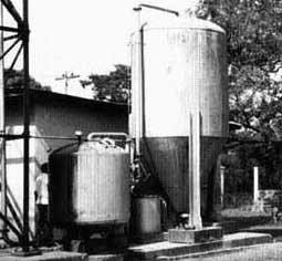
Photo 1 Compact Plant An Example of
Conventional Water Treatment
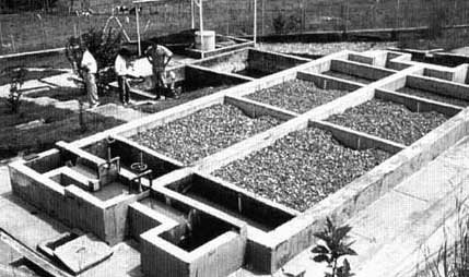
Photo 2 Roughing and Slow Sand
Filter - An Alternative Treatment Option
|
A Blue "White Elephant"

A Blue "White Elephant"
William, the driver of the project car, and I were heading
north of the capital of a country in West Africa. The midday sun was beating
down on the paved road, the air was vibrating and I felt drowsy from the heat.
We were nearing Ndikinimeki, a small administrative centre of the province.
Suddenly, I spotted a few dark blue dots in a banana plantation about 150 m off
the main road. I ordered William to stop the car at once, which he did some 30 m
further on. We drove back to a small path leading to the plantation where some
people were waiting for transport to Ndikinimeki I asked them to see the
treatment plant manager but he was in town.
The first 100 m we drove to the treatment plant, but had
to leave the car next to a bridge and walk the last 50 m. The main gate was
locked, so we climbed over it and stood on a plot which had originally been the
treatment plant premises but had now been partly converted into farmland. Nice
banana trees were growing on the fertile and humid soil located along the
river.
The treatment plant consisted of about seven large ship
containers standing on small concrete foundation blocks. All the containers were
painted blue and had large doors. We climbed on one of the containers to study
the treatment scheme. The plant was apparently designed as conventional
treatment scheme comprising prechlorination, aeration, coagulation, pH
correction, flocculation, sedimentation, rapid sand filtration, pH control, and
disinfection. However, wafer was not flowing through the different treatment
stages. Only the cascades and the sedimentation tanks were partly filled with
rain water which had collected during the wet season and had ended a few weeks
ago.
We rejoined the ground and tried to fight our way through
the vegetation and pipe fittings scattered all over the plot. We managed to
reach one of the side doors which we opened and were horror-stricken by what we
saw. Corroded dosing pumps were still on the containers, some were falling to
pieces, electric cables from the switchboard were hanging loosely from wall to
wan and, in the far end of the container, we discovered a pair of sandals
focally called flip flop. As we opened another container used as storeroom for
the chemicals, a few lizards disappeared through corroded holes and two meagre
bags of alum sulphate were lying in a corner. The last container contained the
general switchboard. Two red bulbs were still burning and the small display
indicated 004 382 pumping hours. Hence, the plant was about two years in
operation if water was pumped for six hours a day.
William was rather angry as we left this place of "quick
money". He realised that this represented a big loss to his country. He
calculated that with the same amount of money about fifty sturdy roughing and
slow sand filter plants could have been constructed, providing some income to
local contractors as well as a good and durable investment for public welfare.
At this point, we passed a large European-style villa with blue window shutters,
located in a large lawn and enclosed in high walls ... |
2. Water treatment concept
Water Treatment is usually a complex process which is
often bound to fail if the objectives are not defined, the raw water properties
not closeIy examined and the treatment methods inadequate. With a clear
treatment concept, including a reasonable appreciation of the raw water
characteristics and seasonal variations of the water quality, logically combined
with the most appropriate treatment processes, failures can be avoided.

Fig. 2 Solid Matter Content in
Surface Water

Fig. 3 Multiple Barrier Water
Treatment Concept
A bucket filled with turbid river water, as illustrated
in Fig. 2, often contains floating matter, such as debris of wood, leaves and
grass, fine and coarse sand, which has settled at the bottom, and some fine
suspended matter in the form of silt and clay particles or algae. However,
harmful microorganisms, carriers of so many infectious diseases transmitted
by consumption or contact with polluted water, cannot be detected with the naked
eye. The size of such organisms, such as protozoa, bacteria and viruses,
range within a few micrometers (1 mm is a thousandth of a millimetre) or even
less. Removal or inactivation of these pathogenic organisms should, however, be
given first priority in any water treatment concept. A difficult task,
considering their small size and possibly low concentration in such a large
volume of water. Slow sand filtration and chlorination are thus the two
most widely used treatment processes, as they are capable of improving, in
particular, the microbiological water quality.
The efficiency of chlorination and slow sand filtration is
strongly influenced by the level of turbidity of the water to be treated.
Turbidity mainly reflects the amount of fine suspended solids present in the
water. A large number of microorganisms, tired of swimming around, attach
themselves like "boat people" to the surface of these solids. The solids protect
the microorganisms from the deadly chlorine. In slow sand filters, the pathogens
will triumphantly observe how the fine particles block the sand surface. Hence,
an efficient use of chlorine and slow sand filters is only possible with a
low water turbidity virtually exempt from sol id matter.
As illustrated in Fig. 3, water has to undergo a step-by-step
treatment, especially if it contains differently sized impurities. The first
and easiest step in sound water treatment schemes is coarse solids separation.
Finer particles are separated in a second pretreatment step and, finally, water
treatment will end with the removal or destruction of small solids and
microorganisms. These different pretreatment steps will contribute to reducing
the pathogenic microorganisms. The '´boat-people" or pathogens attached to
the surface of suspended solids will get stranded when the solids are separated.
Some of the microorganisms floating in the water might also get pushed to the
surface of the treatment installations and adhere to biological films. Solid
matter and microorganisms, therefore, face a multitude of treatment barriers.
Since treatment efficiency of each barrier increases in the direction of
flow, it becomes increasingly difficult for the impurities to pass through each
subsequent treatment barrier.
Surface water treatment thus requires generally at least two
treatment steps as shown in Fig. 4. The first step, also called pretreatment,
concentrates mainly on the removal of solids. Screens, grit chambers,
sedimentation tanks, gravel and coarse sand filters are typically used as
pretreatment units. The second step, commonly considered as main treatment, is
used especially to remove or destroy the remaining microorganisms and the last
traces of solid matter. Slow sand filtration and chlorination are the most
commonly applied treatment processes in this second step.

Fig. 4 Surface Water Treatment in Two
Stages
3. Raw water quality
3.1 Raw water characterisation
Surface water must generally be treated before it is used as
drinking water as it is highly exposed to natural and man-made pollution.
The extent of treatment depends, however, on the degree of water pollution
to be assessed prior to designing any treatment facility. The design of a
rural water treatment plant is based mainly on the following important water
quality parameters:
· turbidity
· true colour
·
solids concentration
· degree of faecal
pollution
Quite often, however, hardly any information is available on
the surface water quality of a raw water source meant for a rural water
supply system. In such a case, the following preliminary surface water
quality assessment steps can be used:
· sanitary inspection of the
catchment area
· water quality analysis of
the raw water
Reference [6] contains a detailed description of these two main
rural water quality assessment steps. The information obtained through a
sanitary inspection is more of a qualitative or descriptive nature and
reflects the long-term situation of an assessed water course. The results of
a water analysis present a quantitative assessment of the examined water
source, and might only reflect the actual water quality at the time of sampling.
Both methods complement each other, however, a thorough sanitary
inspection of the catchment area often provides a more reliable and practical
method of risk identification and general water quality assessment. Several
water analyses have to be carried out to determine extent, duration and
frequencies of water quality fluctuations. However, such information is rarely
available prior to treatment facility design. Water quality analysis is often
performed at a later stage to monitor only the performance of constructed
treatment plants.
Detailed information on raw water quality will ease filter
design. Nevertheless, accurate prediction of filter performance is hardly
possible due to the complexity of filter
processes.
3.2 Catchment area
An overall characterisation of the catchment area and its
hydrology, along with a sanitary inspection of the area, can provide relevant
information on the raw water quality. The specific characteristics of the
catchment area, such as climate, hydrogeology, topography, vegetation, as well
as human and animal activities greatly influence the qualitative and
quantitative levels, as well as the surface water variations. Total rainfall and
its annual distribution, together with soil conditions and topography, are
significant criteria influencing the natural characteristics of a flowing
surface water. Human activities, (deforestation, agriculture and settlements) in
the catchment area will induce qualitative and quantitative changes in the
natural regime of the surface water.
Turbidity level and suspended solids concentration are often
correlated with the seasonal fluctuations of a river discharge. The size of
the catchment area usually influences the period of high discharges; short heavy
storms normally affect the discharge of small highland rivers to a greater
extent than of large lowland streams. Inspection of the river bed and its
embankments will certainly provide first-hand information on flow
characteristics of the river. Closer inspection of the bed sediments and
embankments will supply some details on the type of solids carried by the river
at different periods of discharge. Information provided by the locals
will focus more on frequency and length of turbidity peaks rather than on
absolute turbidity levels, which can only be determined with measuring
equipment.
Faecal pollution is not visible in a water sample. Even
clear and pleasant water may carry harmful and disease-causing microorganisms.
Population density, wastewater disposal practice and general public health
condition will influence the bacteriological quality of a surface water. This
quality varies widely, e.g. a highland river draining a well-protected,
unpopulated area has probably a low public health risk level when used as
drinking water, whereas a surface water draining wastewater from a slum area
without proper sanitation facilities will certainly have an extremely high
public health risk level even when used as washwater. Points of surface water
pollution have to be detected by a sanitary inspection of the catchment area.
Source protection is the first step in water treatment. Hence, remedial
actions must be taken when such pollution points are identified. A survey of
the public health condition is necessary to assess the presence of endemic
diseases. Such a survey might also determine the need to improve the
situation with the construction of a water supply system and, particularly, with
the installation of water treatment facilities. Nevertheless, surface water
remains unprotected and is, therefore, permanently exposed to human and animal
faecal contamination and other man-made pollution. As a result it will generally
have to be treated before it is used as drinking water.
|
Water Treatment Starts in the Catchment Area

Water Treatment Starts in the
Catchment Area
Jacob, caretaker of Guzang's water supply scheme fore more
than 20 years, points to the barren hills of the watershed. His sunny nature
becomes serious and he looks quite demoralised. The situation has changed
considerably since the water project was inaugurated. Formerly, the raw water
was tapped from a small clear river which was well-protected by a dense forest.
A sedimentation tankard two slow sand filters were installed right from the
beginning to treat the raw water. Operation of these installations did not pose
any problems in the first few years. It then became increasingly more difficult
and, for the past three years, slow sand filter operation has become very
cumbersome. Now the filters have to be cleaned every two weeks, which leads to
water shortages in the village. The community is blaming the caretaker for this
state of affairs, however Jacob always tries to do his level best to supply
water to the growing number of villagers. This increase in population puts great
pressure on the available land, which is rapidly transformed from water
reservation areas to agricultural plots. plots. Over the years, the community
has expanded into the water catchment area, and deforestation, careless farming
and grazing methods have negatively affected quantity and quality of the small
river.
The delegation from the District Office is aware of
Jacob's dilemma and has promised to tackle the problem from two sides: as
immediate solution, roughing filters will replace the sedimentation tank,
however, in the long run, Guzang's water supply can only be secured by a more
comprehensive protection programme of the catchment area. Farmers in the
watershed will not be sent away from the area but motivated to change to
improved land use methods, such as agroforestry and pasture improvement.
Treatment plant rehabilitation and watershed conservation are essential to
ensure a more sustainable water and food supply to Guzang. |
3.3 Water quality analysis
In rural areas, the main surface water treatment objective is
to improve its bacteriological quality. Drinking water should not contain
any pathogenic organisms, which are often difficult to detect analytically.
Therefore, the bacteriological water quality is analysed for faecal indicators.
The bacteria used for such analysis are faecal coliforms, Escherichia coli and
faecal streptococci present in large concentrations (10 - 1,000 million conform
bacteria are found in 1 gram of faeces) in the faeces of humans and warm-blooded
animals. If waters contain faecal indicators, pathogenic microorganisms are also
considered to be present.
Faecal conform analyses are performed either by the
membrane filtration technique or by the multiple tube method. Field test kits
(e.g. manufactured by DelAgua Ltd. [7] ) are available and generally use the
membrane filtration technique. The multiple tube method is often applied in
central laboratories. The use of field test kits requires some basic training in
test procedures, initial supervision of field analysis and, at a later stage,
correct and careful handling during routine work. To obtain reliable data, the
analysis of faecal coliforms should be carried out by specially trained people.
Type and amount of solid matter is the second most
important aspect in surface water characterisation. Expensive and very sensitive
laboratory equipment has been developed for the analysis of size, shape and
concentration of solid particles. However, such equipment is hardly available
nor necessary for the design of treatment facilities. Even the standard routine
method of determination of the suspended solids concentration is often not
possible as it requires a highly accurate scale, a vacuum pump and a drying
furnace installed in an air-conditioned room. Such equipment is often
unavailable or has fallen into disrepair. Hence, determination of the physical
characteristics of the solids, to be separated by adequate treatment processes,
requires sturdy and simple field test methods.
The physical characteristics of the solid matter can be
assessed by different simple analytical methods easily applied by any treatment
plant operators. These simple tests are described in Annex 1 and include the
following:
- turbidity test by means of a simple tube
- determination of
the settleable solids volume with a test cone
- determination of the
filterability by means of a filter paper
- suspension stability test using a
vessel and turbidity readings
- solid classification test using a common
bottle
- particle size characteristics by sequential membrane filtration
Chemical water quality parameters should be determined on
a case by case basis if water pollution levels caused by hydrogeological
conditions, agriculture or industry are likely to occur. Simple field test
equipment, as described in [8, 9], could be used for preliminary chemical water
quality assessment. Especially, manganese, true colour and water aggressivity
are important parameters which need to be examined. Furthermore, the amount of
dissolved organic matter should be determined as it will greatly influence the
extent of biological activity and oxygen demand in the
filters.
4. Solid matter separation
Let us now examine the first treatment step; i.e., the
separation of solid matter. We might be confronted with a great variety of
solids as observed in our bucket filled with turbid river water. The
variety, illustrated in Fig. 5, is greatly dependent on the type of surface
water and whether natural purification processes can separate part of the solids
or possibly generate undesirable particulate matter by organic growth.
Natural purification should largely be integrated into the treatment
design when determining surface water source and intake location.
Fig. 5 Solid Matter Content for
Separation
Sedimentation and filtration processes are mainly applied for
solid matter separation. These shall be discussed in detail in the next two
sections.
Yet, let us focus first on the peculiarities of the various
types of surface water and their impact on the different solids in the raw
water:
· The properties of the
drained catchment area and the characteristics of the surface water
influence the type and concentration of solid matter in the raw water. Flow
velocity and rate of erosion determine the amount of settleable solids carried
by the water. Flowing and still surface waters greatly differ with
respect to the encountered type of solid matter. The turbulent flow of a water
course may carry coarse settleable solids, which settle in gently flowing or
impounded surface water. Algae found in ponds and lakes contribute to the
suspended solids concentration of the water.
· Flowing surface water
is often subjected to drastic quantitative and qualitative changes. The
annual rainfall distribution influences the seasonal surface water fluctuation
mainly with regard to turbidity and solids concentration. Flowing surface water
will usually carry settleable solids at varying concentrations during different
periods of time. During the dry season, small upland rivers are generally low in
turbidity, however, they can exhibit high short-term turbidity peaks during
heavy rainfalls. Larger lowland rivers may be of moderate turbidity throughout
the year but with relatively long periods of increased turbidity levels.
· In still surface water,
amount and type of solid matter change only gradually in the course of a
year. In fact, the large volume of stored water in lakes, reservoirs and ponds
preconditions the water quality. Coarse inorganic particles settle at the bottom
of the receiving water body, light organic solid debris tend to float on the
water surface, and dissolved organic matter may be transformed by photosynthetic
processes to algae and plankton. Hence, each still water source acts as a
first pretreatment step since the incoming and stored water is exposed to
natural purification. As a result, impounded water is generally characterised by
smaller water quality fluctuations. This higher stability of the raw water
quality usually facilitates treatment plant operation.
· Flowing surface water
carries solids of different sizes, such as coarse sand and silt to fine
clay. Due to the irregular flow conditions, the solids are unevenly distributed
over the cross section of a river bend. Coarse solids drift towards the outer
side of the bend whereas the fine solids are washed to the inner side of a river
bend and form a silting zone. Selecting an appropriate location for the
intake structure contributes to reducing the levels of fine particles which
are difficult to remove in treatment processes. The intake should, therefore, be
placed at the outer or erosion side of a river bend in order to reduce the
abstraction of fine matter and to avoid the silting of intake works.
· Surface water can also
carry coarse floating matter which may block or even damage part of the
water supply installations. The undesirable material is thus retained right from
the beginning either by screens or by a scumboard. Fixed screens (e.g. a
coarse screen followed by a finer one) are most commonly used to avoid
blockage and excessive headlosses.
In short, if surface water is used as raw water source in a
water supply scheme, preference should be given to still water provided excess
amounts of algae or colour do not create special treatment problems. Natural
purification processes reduce in particular the solid matter concentration by
sedimentation, and smaller water quality variations often decrease and simplify
the required degree of treatment. Flowing surface water frequently exhibits
rapid water quality changes which render water treatment more
difficult.
4.1 Sedimentation
Small pebbles or sand particles will undoubtedly settle in still
water. This process, called sedimentation, is dependent on the physical
properties of the solid matter and water. The settling velocity is influenced by
density, size and shape of the particle, as well as by viscosity and hydraulic
conditions of the water. Stilling basins and sedimentation tanks are quite
efficient in removing relatively heavy and coarse solids, such as sand and
silt particles. Inorganic matter larger than about 20 mm (0.02 mm) can usually
be removed by plain sedimentation and without the use of chemicals.
Stilling basins can often be installed in small rivers.
As shown in Fig. 6, a small weir is placed in the water course to raise the
water depth and to reduce the flow velocity. Easily settleable matter can now be
separated in the backwater of the weir equipped with a small gate to ease
periodic removal of the settled material. The intake of the water supply scheme
may be integrated into the sidewall of the weir, in a zone with sufficient water
current to achieve removal of floating matter retained by the scum-board.
Sedimentation tanks are either rectangular, square, or
circular in shape. The tanks are operated on a continuous or intermittent basis.
In continuously operated tanks, the flow direction is either horizontal or
vertical. In circular tanks, the flow pattern is complex, and the conditions are
unstable in vertically operated tanks. Therefore, rectangular tanks operated
on a horizontal flow and continuous basis are recommended for rural water
supply schemes.

Fig. 6 Layout and Design of a
Stilling Basin
Fig. 7 Layout and Design of a
Sedimentation Tank
Sedimentation tanks separate finer solids, such as silt, clay
and part of the suspended solids. The raw and turbid water enters on one
side of the tank and is evenly distributed over the entire tank cross section.
The solids then settle under laminar flow conditions to the tank bottom, and the
clarified water is abstracted uniformly over the full width on the opposite side
of the tank. In order for the particles to separate, each solid particle has
to overcome a settling distance equal to the tank's depth, e.g. around 1 to 3 m.
The accumulated sludge is periodically removed from the tank bottom. The
solids removal efficiency of a sedimentation tank depends mainly on the
hydraulic surface load, tank depth, and retention time. Some general design
values fore sedimentation tank are given in Fig. 7, however, they should be
chosen according to the settling characteristics of the solids. These can be
determined in a sedimentation test using a transparent test tube; for additional
information consult Annex 1. The recorded time necessary to attain a certain
clarification level in the test has to be multiplied by a factor three to allow
for unfavourable flow conditions in a full-sized tank. Low surface loads should
be applied with raw water of poor settling properties, and in small plants with
variable operating conditions.
Even properly designed and operated sedimentation tanks will
separate only part of the suspended solids. With the help of coagulants,
such as alum or iron salts, suspensions can be destabilised. The small particles
lose their repulsive force, cluster together and coalesce to larger floes of
improved settling characteristics. Coagulants are extensively used in
conventional water treatment systems. However, the flocculation/sedimentation
process is already an advanced treatment technique requiring qualified
personnel and well-equipped facilities; both scarce in rural areas of developing
countries. Chemicals often have to be imported from abroad and paid for in
foreign currency. Since transport problems are pertinent to many developing
countries, the adequate and reliable supply of chemicals to remote treatment
plants is yet another stumbling-block. Dosage is also an art in itself, as it
must be adapted to the varying raw water quality and thus requires professional
water quality monitoring. Accurate and sensitive dosing instruments are attacked
by the corrosive action of the chemicals. Chemical water treatment calls for
skilled personnel trained in water quality monitoring, dosage adjustment, as
well as in maintenance and repairs of dosing equipment. Finally, use of
chemicals often greatly increases operating costs. In practice, rural water
supplies often face considerable problems with chemical water treatment. A
reliable and successful application of chemical flocculation is, therefore,
rather unrealistic for many small water supply schemes. The chemical coagulation
and sedimentation process applied in conventional water treatment schemes for
separation of suspended solids and colloidal matter will generally fail in rural
water supply schemes and is therefore not recommended.
To conclude, it can be said that stilling basins and
sedimentation tanks are quite efficient in removing coarse and easily settleable
solids. They are used as preliminary treatment step, especially to treat raw
water drawn from running water courses containing high solids concentrations. In
rural water supply schemes, use of chemicals to enhance sedimentation by
flocculation is difficult and, therefore, quite
unreliable.
4.2 Roughing filtration
The water quality of contaminated surface water can be
improved significantly when filtered through gravel and sand layers.
Therefore, favourable hydrogeological conditions allow polluted and turbid
river water to be drawn as clear and safe groundwater from a shallow well
located next to a river. However, local soils are quite often impervious for
lack of gravel and sand layers. Nevertheless, why should nature's excellent
purification capacity be ignored just because of unfavourable hydrogeological
conditions at the site of a new water supply scheme? Let us then copy nature and
construct an artificial aquifer by filling a sedimentation tank with gravel. As
illustrated in Fig. 8, the solids removal efficiency of such a tank will
drastically increase due to the greatly reduced settling distance in the gravel
material. In other words, the fine solids crossing an ordinary sedimentation
tank have to overcome a vertical settling distance of 1 to 3 m before coming
into contact with the tank bottom. The same solids flowing through a filter will
fortunately touch the gravel surface already after a few millimetres. Thus,
filtration becomes a more effective process for solids removal since the
settling distance is drastically reduced by the filter material. Presence of
a small pore system and large internal filter surface area enhances
sedimentation and adsorption, as well as chemical and biological activities.
Design and application of prefilters vary considerably.
The different filter types are classified according to their location within
the water supply scheme, their main application and flow direction. Intake and
dynamic filters, which often form part of the water intake structure, differ
from actual roughing filters which are generally located at the water treatment
plant. As illustrated in Fig. 9, roughing filters are further subdivided into
down, up and horizontal-flow filters. Finally, vertical-flow filters can be
classified according to the manner in which the gravel layers are installed. The
different gravel fractions of roughing filters "in series" are installed in
separate compartments, while those of roughing filters "in layers" are placed on
top of each other in the same compartment.
Fig. 8 Particle Removal in a
Sedimentation Tank and a Roughing Filter
Roughing filters usually consist of differently sized filter
material decreasing successively in size in the direction of flow. The bulk
of the solids is separated by the coarse filter medium located next to the
filter inlet. The subsequent medium and fine filter media further reduce the
suspended solids concentration. The filter medium of a roughing filter is
composed of relatively coarse (rough) material ranging from about 25 to 4 mm in
size. Gravel is generally used as filter material. Significant solids
removal efficiencies are only achieved under laminar flow conditions since
sedimentation is the predominant process in roughing filtration. Therefore,
roughing filters are operated at small hydraulic loads, which have been
defined as flow rate Q divided by the filter area A perpendicular to the
direction of flow. Filtration velocity, synonymous with hydraulic load, usually
ranges between 0.3 and 1.5 m/h. The coarse filter material and the small
hydraulic load limit filter resistance to a few centimetres.

Fig. 9 Classification of Prefilters
Filter cleaning is carried out manually and hydraulically
depending on the pattern of solids accumulated in the filter. Intake and
dynamic filters separate the solids mainly at the inlet zone of the filter and,
thus, act as surface filters. These filters are therefore manually cleaned by
scouring the top of the filter bed with a shovel or rake. Compared to intake and
dynamic filters, roughing filters act as space filters on account of the deep
penetration of the solids into the filter medium. The accumulated solid matter
is periodically flushed out of roughing filters by hydraulic filter cleaning. If
necessary, these filters can be cleaned manually by excavating the filter
material from the filter compartment, washing and refilling it into the filter
boxes.
Sedimentation is the main process in roughing filtration.
It is responsible for solids separation from the water as observed in
laboratory tests conducted with roughing filters [10, 11, 12, 13,14]. The
filter acts as multi-storage sedimentation basin since it provides a large
surface area to accumulate the settled matter. As shown in Fig. 10 and
illustrated in Photo 3, the deposits are retained on top of the collectors where
they grow to dome-shaped aggregates with advanced filtration time. Part of the
small heaps drift to the filter bottom when the loosely accumulated aggregates
become unstable. In horizontal-flow roughing filters, this drift regenerates
filter efficiency of the upper gravel layers and allows accumulation of a
considerable amount of retained material at the filter bottom. Depending on the
organic characteristics of the raw water, other processes such as biological
oxidation or adsorption of solid matter at the slimy filter surface may occur.
Under these circumstances, enhanced aggregation and consolidation of deposits
have been reported [12]. This poses inherent difficulties during hydraulic
cleaning and filter regeneration.
Fig. 10 Solid Removal in a
Horizontal-flow Roughing Filter
Filter regeneration can be enhanced by filter drainage.
The loosely accumulated aggregates collapse and are washed down to the
filter bottom if the water table in the filter is lowered. Part of the
accumulated solids can be flushed out of the filter with high filter drainage
rates and adequate installations.

Photo 3 Accumulation of Kaolin in a
Horizontal-flow Roughing Filter after 24h, 100h, and 300h of Filter
Operation
5. Bacteriological water quality improvement
The water in our bucket is now clear but still unsafe for
consumption. The turbid river water has changed its appearance as the solid
matter has been separated by the pretreatment processes discussed in the
foregoing chapter. The water has lost its brownish tinge and turned into a clear
and pleasantly looking liquid. However, the water is still not as pleasant and
safe as it looks. As schematically shown in Fig. 11, disease-causing pathogenic
microorganisms are usually not visible to the naked eye of the consumer who
could get a severe attack of diarrhoea a few hours after drinking this water.
Hence, the pretreated water still needs further treatment for final
removal or inactivation of pathogens. Slow sand filtration and chlorination
are the two most commonly applied treatment processes for bacteriological
water quality improvement.
Fig. 11 Microorganisms for
Separation
5.1 Slow sand filtration
Slow sand filtration plays a key role in rural water treatment.
Design and application of this treatment process is well-documented in the
available literature [15, 16, 17]. Since slow sand filters reduce the number of
microorganisms present in the water, they improve the bacteriological water
quality. In addition, fine organic and inorganic matter is separated, and the
organic compounds dissolved in the water are oxidised. Since the effluent of a
well-designed and operated slow sand filter is virtually free from pathogenic
microorganisms, water treated by such a slow sand filter is safe for
consumption. Furthermore, a comparative evaluation [18] of slow sand and rapid
sand filter efficiencies revealed that slow sand filters are more efficient in
the removal of several commonly occurring pesticides. In contrast, they were
found to be poorer than coagulant-assisted rapid sand filters for the removal of
dissolved organic carbon and organic colour. However, slow sand filtration is
one of the most efficient processes for the production of hygienically safe
drinking water with a possibly small bacterial regrowth.
The slow sand filter technology copies nature. The sand
layers of aquifers convert unsafe surface water into good quality drinking
water. Especially the harmful bacteria, viruses, protozoa, eggs, and worms are
most effectively removed by physical and biochemical processes to a level which
no longer endangers human health. These natural purification processes are also
used by the slow sand filters - a technology which was introduced last
century. At that time, Europe was struck by cholera epidemics, which forced
the waterworks to take quick action. The advantages of slow sand filtration were
then discovered. This water treatment technique proved to be efficient against
water-borne diseases and, in combination with other public health improvements,
these epidemics were eradicated in Europe. Numerous water supplies in
industrialised countries are still using slow sand filters. Thames Water
supplies for instance two thirds of London's population with slow sand filter
treated surface water drawn from the River Thames which carries a very high
percentage of sewage effluent from upstream settlements during drought years.
This is a tribute to the efficiency and reliability of the slow sand filter
technology.
The layout of slow sand filters is simple and
straightforward. As shown in Fig. 12, a slow sand filter contains an open
box filled with a sand layer of a depth of about 0.8 to 1.0 meter. The upper
part of the filter box is filled with water flowing by gravity through the sand
bed. The filtered water is then collected by an underdrain system and conveyed
to the clear water tank. The well-graded sand of the filter bed is relatively
fine; i.e., its effective size ranges between 0.15 and 0.30 millimetre, but
recent field experience revealed that also somewhat coarser sand can be used
[4].
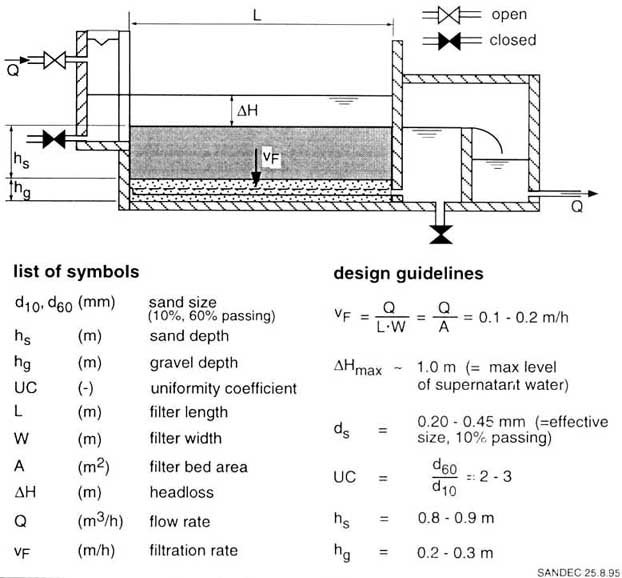
Fig. 12 Layout and Design of a Slow
Sand Filter
Slow sand filter operation is easy and reliable. Slow
sand filters are usually operated at 0.1 to 0.2 m/h filtration rates.
Consequently, an area of 1 m² sand produces about 2.5 to 5 m³ of water
per day. The flow rate is preferably controlled at the filter inlet, and the
water level is maintained at a minimum level above the sand bed by means of a
weir or effluent pipe located at the filter outlet. Effective biological
treatment can only be achieved if a reasonably steady throughput is maintained.
Therefore, a 24-hour operation is recommended as it makes maximum use of the
available filter installations. The initial filter resistance of a clean sand
filter ranges between 0.20 and 0.30 meter. The headloss gradually increases with
progressive filtration time. The sand filter has to be cleaned when filter
resistance amounts to about 1 meter.
Slow sand filters act mainly as surface filters. The
water quality changes at the surface of the sand bed, in the so-called
"Schmutzdecke" and, to a lesser extent, in the first 20 to 30 centimetres of the
send bed. A thin layer on the surface of the sand bed, formed by retained
organic and inorganic matter, and a large variety of biologically active
microorganisms, are responsible for the physical, chemical, and biological
improvement of the water. This thin biological layer must first develop in a new
slow sand filter. The initial ripening period normally requires two to four
weeks. Cleaned filters will regain their full biological activity within two to
four days, provided shut down time for filter cleaning is short; i.e., not more
than 6 - 12 hours.
Filter cleaning must be carried out once the supernatant
water has reached its maximum permissible level; i.e., when maximum filter
resistance of about 1 meter is attained for the designed filtration rate. Filter
cleaning starts with drainage of the supernatant water and dewatering of the top
part of the sand bed. Subsequently, the biological skin and 1 to 2 centimetres
of sand are removed from the sand bed as shown in Photo 4. Resanding is possibly
performed after removal of the top sand layer. Thereupon, filter operation is
immediately restarted to avoid disrupting biological filter activity more than
is necessary. The filter bed is refilled with water introduced via the
under-drainage system. This drives the air out of the pores of the sand and
completely saturates the filter bed. Normal operation is then reassumed by
opening the inlet valve and adjusting the filtration rate.
Well-operated slow sand filters should at least achieve more
than 1 to 3 months of filter runs. The term "filter run" is defined as the
time between two subsequent filter cleanings. In order to realise such long
filter runs, slow sand filters have to be supplied with relatively clear water.
Reasonable filter operation can only be expected with inlet water turbidities
below 20 to 30 NTU. Higher turbidities, with consequently higher solids
concentrations, will rapidly clog the sand surface and interfere with the
biological processes. Hence, it is strongly recommended that surface water is
pretreated prior to slow sand filtration.

Photo 4 Cleaning of a Slow Sand
Filter
Design deficiencies will cause problems to slow sand filters.
In the past, several slow sand filter plants in developing countries have
faced operational problems or had to be closed down. Serious design faults,
inadequate operation and poor water quality supplied to the slow sand filters
are the main reasons for the problems and failures experienced. As illustrated
in Fig. 13, a lack of flow control equipment, inadequate pipe installations, a
soiled and poorly graded sand which does not conform to the recommended size, or
missing water level control systems, are the most common design errors
encountered. Random filter operation under variable and often too high
filtration rates by insufficiently trained caretakers, are generally the causes
of inadequate filter efficiency.
Poor quality raw water, inadequately pretreated, also
contributes to poor slow sand filter performance. Frequently, slow sand
filters are directly fed with raw water or are often combined with inefficient
or inappropriate pretreatment processes. Slow sand filters usually face serious
operational problems when chemical flocculation and sedimentation are used as
pretreatment. The local caretaker might not be able to control flocculation as
it is an unstable pretreatment process difficult to operate. Light floes often
get washed onto the slow sand filters, or a lack of chemicals greatly reduces
the solid removal efficiency of the sedimentation tank. Premature, rapid filter
clogging and frequent filter cleaning are the resulting consequences. Therefore,
efficient pretreatment of the surface water, such as for instance by roughing
filters, is necessary to avoid serious operational difficulties with slow sand
filters. Small slow sand filter units receiving raw water of moderate turbidity
can also be protected by layers of non-woven synthetic filter fabrics [19,20] or
by a layer of gravel [21 ] installed on top of the sand bed.

Fig. 13 Common Design Faults of Slow
Sand Filters
In summary, slow sand filtration can thus be regarded as a
safe, stable, simple and reliable treatment process. Filter construction makes
extensive use of local material and skills. Filter operation neither requires
sophisticated mechanical parts nor the use of chemicals. Construction, operation
and maintenance of the filters are easy and require only limited skills.
However, adequate filter operation is only possible with raw water of low
turbidity; i.e., virtually free of solid matter. Pretreatment of surface water
is therefore necessary. In combination with adequate pretreatment methods, slow
sand filtration is considered a most appropriate water treatment technology for
developing countries.
|
Defective Slow Sand Filter Next to the Cemetery
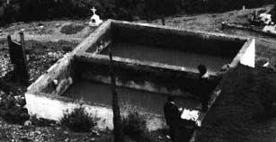
Defective Slow Sand Filter Next
to the Cemetery
The photograph is self-explaining. From the slope of a
steep valley in the Andean highlands we can see two slow sand filter units
filled with chocolate coloured water, a large heap of sand deposited on the soil
next to the structure and, slightly further down, the cemetery of the village
whose population is supplied by the water of these defective filters. Mist is
climbing from the valley and will soon engulf this gloomy vision .....
In 1985, DelAgua evaluated the 18 treatment plants in two
departments of the Andean country. Two of the plants had inoperative rapid sand
filters. The study also revealed that all the slow sand filter and disinfection
units had major deficiencies and operating problems. Technical and institutional
problems were responsible for these failures. The main technical problems were
associated with the flow control and raw water quality. Absence of a flow
control at the raw water intake caused unstable or intermittent filter
operation. The highly turbid and contaminated raw water was not adequately
pretreated and led to short filter runs and operational problems. Consequently,
filter efficiency was considerably reduced and, according to the survey, more
than half of the plants could reduce only marginally or not at all turbidity and
bacterial contamination. As regards institutional aspects, the caretakers and
administrative committees had not received adequate training in treatment plant
operation and maintenance. The users were not given professional supervisory
support from the responsible national authorities which had no incentive to
providing a reliable water supply. The described problems were tackled by a
rehabilitation and technology transfer programme for rural water treatment.
Effective and appropriate pretreatment processes, such as roughing filtration,
were introduced, and institutional development as well as community education
were supported.
To ensure a reliable and sustainable treatment plant
operation, appropriate treatment processes and local development of technical
and managerial skills are required. |
5.2 Chlorination
Chlorination aims at destroying or, at least, inactivating
harmful microorganisms, such as pathogenic bacteria, viruses, and cysts present
in the water. Chlorine is a strong oxidant, which not only reacts with
the enzymes vital to the metabolic processes of living cells, but is also
responsible for other chemical reactions. Dissolved organic matter, for
instance, depletes by fast chemical reaction the available chlorine that will
then be unavailable for water disinfection. Or chlorine reacts with nitrogen to
form the more stable chloramines often purposely generated by the addition of
ammonia to the water so as to cope with any type of pollution problems in the
distribution system.
The advantages why chlorination is widely used in water
treatment practice are the following:
- Chlorine is a strong disinfectant when applied to low water
turbidity with a small dissolved organic content.
- Residual chlorine content is extremely simple to determine by
calorimeters, which is not the case for other disinfection processes such as
ozone or UV radiation.
- Since chlorination installations are relatively small, they do
not require large civil engineering structures and their investment costs are
relatively low.
- Chlorine is often applied as a safeguard (especially in the
form of stable chloramines) against secondary water pollution. Although small
quantities of chlorine may deal with minor contaminations resulting from
incorrect water handling at household level, they will never be able to combat
heavily contaminated water caused by cross-connections or wastewater
infiltration in intermittently operated water supply systems.
Numerous disadvantages of chlorination, however, question
the application of this water treatment process in rural water supply schemes.
Chlorination is associated with the following problems:
- Chlorination requires a reliable water treatment system. It is
neither applicable to turbid water nor to water of high organic content.
- With inadequately pretreated water, chlorine forms by-products
(e.g. trihalomethanes) that are considered carcinogenic.
- Chlorine is usually an unstable and corrosive chemical that
loses its disinfecting power during storage, and attacks the delicate
installations in the dosing room.
- Dosing equipment and chemicals must often be imported, which
leads to a foreign currency demand and high operating and maintenance costs.
- Consumers frequently refuse to drink chlorinated water for
reasons of taste and odour.
Accurate chlorine dosage is essential to attain efficient
disinfection. Only partial disinfection is achieved with chlorine dosages lower
than the chlorine demand of the water. Water containing a too high chlorine
concentration might not be accepted by the consumers, as chlorinated water has a
distinct odour. A strong smell develops when chlorine reacts with ammonia to
form chloramines. People often reject chlorinated water even when
chlorine is carefully handled and dosed at low concentrations.
Chlorine is available in gaseous, solid, and liquid form.
Chlorine gas is extremely toxic, difficult to handle and, therefore, usually
inappropriate for rural water supplies. Chlorinated lime, commonly known as
"bleaching powder", calcium hypochlorite powder, or sodium hypochlorite
solution, also called "Javel water", are used as chlorine derivatives. Since
a chlorine solution is preferably added to the water, chlorinated lime and
calcium hypochlorite should be dissolved in the water to a stock solution
containing usually 1 to 3 percent active chlorine. Chlorine solutions require
careful preparation; i.e., it is extremely dangerous to spill water on dry
hypochlorite. Fig. 14 summarises the different chlorine applications. Please
note that adequate disinfection is attained not only with a sufficient chlorine
concentration C (mg/l), but also requires an appropriate contact time T (min) as
the inactivation of mircroorganisms is dependent on the product C x X.
A constant rate of chlorine solution is added to the water by
dosing devices. The relatively small doses of chlorine call for accurate
dosing equipment. These are, however, exposed to the corrosive action of the
chlorine and often get damaged. The dose has to be adjusted to the chlorine
demand of the water to be disinfected. In practice, a limited chlorine dosage
adjustment is possible, e.g. on a day-to-day basis. Reliable water treatment
prior to chlorination is consequently necessary. Adequate water disinfection
is generally feasible only with water virtually free of solid and organic
matter.
Fig. 14 Application of Chlorine
A reliable supply of chlorine is often difficult to obtain.
Chlorine must be purchased on a regular basis as its unstable nature does
not allow lengthy storage. Chlorine generally has to be imported and, thus,
requires foreign currency; an often scarce amenity in developing countries. In
addition, these countries usually face other difficulties, such as communication
and transportation problems. Finally, chemical water treatment requires skilled
personnel often unavailable in rural areas. All these aspects are a stumbling
block to a reliable and efficient chlorine application and, more generally,
to the use of chemicals in rural water supply schemes in developing countries.
This observation is endorsed by numerous cases of malfunctioning or abandoned
chemical water treatment installations.
Since conventional disinfection methods are generally
unsuccessful in small rural water supply schemes, simple, robust and easily
maintained low-cost, reliable methods of disinfection are thus necessary.
New water disinfection techniques have already been
developed and field-tested [22]. The use of iodine instead of chlorine bound
onto resins housed in a cartridge is but one alternative. By placing this
cartridge in the water, the microorganisms are rendered non-viable by oxidative
reaction with iodine. Compared to chlorine, iodine does not react so easily with
organic compounds in the water. However, this disinfection method requires
further development before it can be used on a larger scale, especially with
regard to fixing the iodine on an adequate supporting material. Furthermore,
dosing of iodine must be well-controlled - at high dosage, it may pose a health
hazard, particularly to pregnant women.
The use of an electrolytic cell which produces an oxidising
gas when an electrical current is passed through a saturated sodium-chloride
solution is a second water disinfection alternative. The Moggod method ("mixed
oxidant gas generated on demand") requires salt, water and electric current to
produce a strong oxidising gas. This method, however, is sensitive to the use of
normal salt as it creates substantial problems when associated with calcium and
magnesium deposits on the membrane. Further investigations on the nature of the
gas produced and on operational aspects regarding the use of low-quality salt,
are necessary before this disinfection method can be recommended for wider use.
The described methods suggest different processes rather than
real disinfection alternatives to replace or produce chlorine at the site. Other
processes (e.g. the MIOX method) are being developed and field-tested. A
comprehensive description of chlorination and alternative disinfection methods
is beyond the scope of this manual, however, reference is made to the relevant
literature [23, 24, 25].
To conclude it can be said that an efficient and reliable
disinfection with chlorine requires pretreated water virtually free of solid and
organic matter. The use of chlorine in rural water supply schemes often creates
enormous problems and is, therefore, frequently bound to fail as documented by
numerous treatment plants. Furthermore, the rural population often rejects
chlorinated water. Thorough technical, institutional and sociocultural
investigations are necessary before chlorination is introduced in rural water
treatment.
|
Chlorinated Water "Not for Drinking"
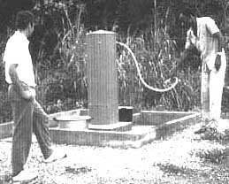
Chlorinated Water "Not for
Drinking"
One could almost smell the paint on the recently
constructed public standpost. Its design differs from the many other thousands
used around the world. The local standpost uses water siphons with flexible
tubes. A floating valve maintains the water at a constant level in the closed
steel cylinder. This prevents leaks or broken down taps due to frequent public
use. However, the interest of our group, composed of representatives of the
foreign consultant and supplier and led by a Desk Officer of the national water
company and the local Director of the water supply, was not only restricted to
this special standpost design but to the entire water supply system. The system
visited was the first of four which had just started operation. Construction of
an additional twelve schemes was under discussion. All the water supply schemes
were identical in design; i.e., a surface water intake, water treatment
consisting of pre-chlorination, pH-control, aeration, coagulation with alum
sulphate, flocculation, tilted plate settlers, rapid sand filtration, and final
disinfection, as well as a clear water pumping station supplying the reservoir
and distribution scheme. A module system for the treatment plant allowed rapid
and efficient construction. However, we had some doubts whether the river water
draining dense and unpopulated woodlands would require such extensive treatment
in this location. The abstracted raw river wafer was quite clear even during our
visit in the rainy season. Nevertheless, the water, which ran through the
different treatment stages, was still treated with chemicals.
Two girls passing by the standpost were asked by the Desk
Officer of the water company if they enjoyed the new water supply. Their answer
was unexpected and also depressing as they declared that the water supply was
used for many other purposes than for drinking. On account of its artificial and
strange taste, the distributed wafer was not consumed by them, their families
nor by the villagers. This is why they still draw water from the nearby
river. |
6. Layout of a water supply scheme
6.1 General considerations
From the technical point of view, the following three main
questions have to be answered during the planning phase of a water supply
scheme:
· which raw water source
should be used for the water supply scheme?
· if treatment is necessary, what type of
treatment scheme should be favoured?
· how
much water should be distributed to the consumers, and at what service
level?
Source selection is a very basic decision entailing
numerous consequences for the future water supply scheme. The different local
water sources have to be evaluated with respect to their quantity, quality
and accessibility. The future water demand must be covered by the selected
source with the best possible water quality, and located as close as possible to
the supply area.

Fig. 15 Layout Possibilities of water
supply Schemes Using Surface Water
Since water treatment is usually the most difficult
element in any water supply scheme, it should be avoided whenever possible. The
general statement that no treatment is the best treatment especially
applies to rural water supply schemes which generally exhibit a poor
infrastructural and institutional framework to adequately maintain water
treatment facilities. The use of better water quality sources is, therefore, an
alternative which will always have to be taken into serious consideration. If no
other alternative is available, rural water treatment must concentrate on
improving the bacteriological water quality by locally sustainable treatment
processes.
Water distribution systems depend on the type of water
source used, on the topography, and on the provided supply service level.
Individual water supplies, e.g. rainwater harvesting and shallow groundwater
wells equipped with hand pumps usually do not need piped supply systems. Treated
surface water, however, is normally distributed by a piped system. A suitable
topography often allows the installation of a gravity system which will
improve reliability and supply continuity. Since pumped water supply schemes
depend on the reliable supply of energy and spare parts, they are very
susceptible to temporary standstills. Finally, the service level of water supply
strongly governs water demand. Water usage increases drastically with the
provided service level, e.g. public standpost, yard connection, multiple tap
house connection. Water supply is always interlinked with wastewater
disposal. The health situation of a community supplied with treated water
does not necessarily improve, especially if public health and wastewater
disposal issues are neglected. The main components necessary to significantly
improve the public health situation of a community are therefore a reliable and
safe water supply, an adequate waste disposal system and a comprehensive hygiene
education programme.
As schematised in Fig. 15, surface water has to be collected,
treated and stored before it reaches the consumer. These activities can be met
by different water supply layout options. Figs. 15 and 16 only illustrate some
arrangement
examples.
6.2 Hydraulic profile
Selection of the hydraulic profile is a basic criteria when
planning a water supply scheme. First choice must be given to gravity supply
systems since they guarantee reliable operation at low running costs.
Schemes, which integrate the use of handpumps, are given second choice. The
installation of mechanically driven pumps should be chosen as last option and
only applied in special cases where a reliable and affordable energy supply is
guaranteed, including the infrastructure for pump maintenance and repair work.
Hydraulic rams making use of the potential energy of a large water volume to
pump a small fraction of this water volume to a higher level [26] may be an
appropriate option where surface water gravity is available and water volume
abundant. Under special local conditions, collection and pretreatment of the raw
water may be combined in a single installation such as infiltration galleries.

Fig. 16 General Layout of Pumped
Water Supply Schemes
Water treatment plants should, whenever possible, be
operated by gravity and with a free water table to minimise water pressure on
the structures. The total headloss through the treatment plant will amount to 2
or 3 m. In general, any type of water lifting, except through handpumps, should
be avoided as the supply of energy and sophisticated spare parts is generally
unreliable. If water lifting is absolutely necessary for topographical reasons,
the number of pumping steps must be limited. As illustrated in Fig. 16, a
one-stage pumping scheme should be chosen for raw water to be pumped to an
elevated site where the treatment plant and reservoir are located. Such a
one-stage pumping scheme has greater advantages over a two-stage scheme as it
increases its reliability by a factor of 2. Moreover, the risk of flooding in
lowland areas can often not be excluded entirely. Protecting a high-lift pumping
station against floods is easier than a full-sized treatment plant. However, a
two-stage pumping system is unavoidable for a piped supply on a flat area devoid
of natural elevation and in case of serious raw water quality fluctuations, e.g.
heavy sediment loads during the monsoon. In such a situation, installation of a
low lift raw water pump is recommended. It may consist of an irrigation unit of
low efficiency but of simple repair to limit high lift pumping for treated water
and protect impellers and seals from damage. Hence, high lift pumps should be
used for treated water or raw water pumped from infiltration galleries or
similar intake systems.
Fig. 17 Treatment of Surface Water
|
Spring for Minimum Water Supply
Iringa, a town in East Africa of 80,000 inhabitants is
pleasantly located at the edge of an escarpment. The citizens have a beautiful
view of the valley where the Little Ruaha river is gently meandering through
maize and cassava fields. This turbid river is also the main water source of the
town. The river water is pumped to an adjacent conventional treatment plant,
collected in a clear water tank and, in a second step, lifted over the steep
escarpment to the reservoir located in the town. Iringa often faces water
shortage, mainly due to the frequent breakdown of the raw water pumps. The
silt-loaded river water claims its victims in the form of rubber seal wear outs,
impeller grind offs and shaft blockages, which put a great strain on the plant
manager. Quite frequently, none of the raw water pumps are working.
Fortunately, a gravity pipe conveys wafer to the clear
wafer tank from a tapped spring 10 km across the river valley. The powerful
clear water pump can therefore at least be operated for a few hours a day to
lift the clear spring water to the poorly supplied town.
The spring water supply is obviously more reliable not
only for its single pumping step, but also for its better water quality.
Rehabilitation of the intake could significantly reduce the operational
difficulties of the raw water pumps. The intake suction pipes hanging loosely in
the river should be replaced by a grit chamber, or even better by intake filters
or infiltration galleries, which would remove a large fraction of the solids
that considerably reduce the life of any pump. |
6.3 Treatment steps
As discussed in Chapter 2, surface water has to undergo a
step-by-step treatment. Coarse solids and impurities are first removed by
pretreatment, whereas the remaining small particles and microorganisms are
separated by the ultimate treatment step. Under special local conditions, raw
water collection and pretreatment may be combined in a single installation, such
as intake or dynamic filters or, alternatively, by infiltration galleries. Fig.
17 illustrates different schemes for surface water treatment. The required water
treatment scheme is mainly dependent on the degree of faecal pollution,
characteristics of the raw water turbidity and on the available tvpe of surface
water.
6.3.1 Removal of Coarse Material
Separation of coarse solids from the water is preferably
carried out by a high-load sedimentation tank (grit chamber) or by a
plain sedimentation tank, since sludge removal from such tanks is less
troublesome than from roughing filters. Simple sedimentation tanks can be
designed according to the layout and guidelines given in Fig. 7, or constructed
as earth basins as illustrated in Fig. 18.
Use of one sedimentation tank should be sufficient for a
small-scale water supply scheme. The accumulated sludge can be removed during
periods of low silt load. A bypass is required to maintain operation of the
treatment plant during cleaning periods. In order not to interfere too much with
normal operation of larger water treatment plants, two or more sedimentation
tanks operating in parallel should be provided to allow cleaning, maintenance
and repair of one tank.
6.3.2 Aeration
The water's dissolved oxygen content plays a key role in the
biology of the slow sand filtration process. The activity of the aerobic biomass
decreases considerably if the oxygen concentration of the water falls below 0.5
mg/l. Furthermore, nitrification of ammonia is associated with a significant
consumption of oxygen, e.g. 1 mg NH4-N/I requires 4.5 mg
O2/l. Hence, an adequate oxygen content in the water to be filtered
is of prime importance. Physical processes are the main mechanisms in roughing
filtration. However, biochemical reactions might also occur in the prefilters,
especially if the raw water contains high organic loads.

Fig. 18 Design of an Earth Basin as
Sedimentation Tank
Fig. 19 Layout and Design of an
Aeration Cascade
Since turbulent surface waters are generally well oxygenated,
they do not require additional aeration. Still water, however, can exhibit low
oxygen contents, especially when drawn from the bottom of polluted surface water
reservoirs. Multi-level drawoffs are recommended as intake structures for
stratified water bodies to allow abstraction of best raw water quality. However,
stagnant raw surface waters are preferably aerated.
Cascades are simple but efficient aeration devices. A
submerged cascade aerator, as illustrated in Fig. 19, should be installed in
gravity systems with sufficient hydraulic head. The cascade should preferably
precede filters to meet the possible oxygen demand. The different weirs, used
for flow control, are an additional source of oxygen supply.
6.3.3 Roughing Filtration as Pretreatment
Roughing filtration mainly separates the fine solids
which are not retained by the preceding sedimentation tank. The effluent of
roughing filters should not contain more than 2-5 mg/l solid matter to comply
with the requirements of the raw water quality for slow sand filters.
Coarse gravel filters mainly improve the physical water
quality as they remove suspended solids and reduce turbidity. However, a
bacteriological water improvement can also be expected as bacteria and
viruses are solids too, ranging in size between about 10 - 0.2 mm and 0.4 -
0.002 mm respectively. Furthermore, according to the specific literature [27],
these organisms get frequently attached by electrostatic force to the surface of
other solids in the water. Hence, a removal of the solids also means a reduction
of pathogens (disease-causing microorganisms). The efficiency of roughing
filtration in microorganism reduction may be in the same order of magnitude as
that for suspended solids, e.g. an inlet concentration of 10 - 100 mg/l can be
reduced by a roughing filter to about 1 - 3 mg/l. The bacteriological water
quality improvement could amount to about 60 - 99%, or the microorganisms
are reduced to about 1 - 2 log. Larger sized pathogens (eggs, worms) are removed
to an even greater extent.
Roughing filters are used as pretreatment step prior to slow
sand filters. Slow sand filtration may not be necessary if the
bacteriological contamination of the water to be treated is absent or small,
particularly in surface waters draining an unpopulated catchment area, or where
controlled sanitation prevents water contamination by human waste. However,
physical improvement of the water may be required with permanent or periodic
high silt loads in the surface water. Excessive amounts of solids in the water
lead to the silting up of pipes and reservoirs. For technical reasons,
roughing filtration may therefore be used without slow sand filtration if the
raw water originates from a well-protected catchment area and if it is of
bacteriologically minor contamination; i.e., in the order of less than 20 50
E. coli/100 ml.
For operational reasons, at least two roughing filter units
are generally required in a treatment plant. Since manual cleaning and
maintenance may take some time, the remaining roughing filtration unit(s) will
have to operate at higher hydraulic loads. A single prefilter unit may be
appropriate in small water supply schemes treating water of periodically low
turbidity.
6.3.4 Slow Sand Filtration as Main Treatment
The substantial reduction of bacteria, cysts and viruses by
the slow sand filters is important for public health. Slow sand filters also
remove the finest impurities found in the water. For this reason they are placed
at the end of the treatment line. The filters act as strainers, since the small
suspended solids are retained at the top of the filter. However, the biological
activities of the slow sand filter are more important than the physical
processes. Dissolved and unstable solid organic matter, causing oxygen depletion
or even turning to fouling processes during the absence of oxygen, is oxidised
by the filter biology to stable inorganic products. The biological layer on
top of the filter bed, the so-called "Schmutzdecke", is responsible for
oxidation of the organics and for the removal of the pathogens. A slow sand
filter will produce hygienically safe water once this layer is developed.
Unlike roughing filters, the time for slow sand filter
cleaning is determined by maximum available headloss level, and not by
deterioration of effluent quality. This offers some advantages as recording of a
hydraulic criteria is easier than measuring water quality parameters.
Further information on slow sand filtration is summarised in
Annex 3, and detailed information on design and construction of slow sand
filters is provided by different technical manuals [15, 16,17] and proceedings
[28, 29, 30].
6.3.5 Water Disinfection
Water from a slow sand filter with a well-developed
biological layer is hygienic and safe for consumption. Any further
treatment, such as disinfection is, therefore, not necessary. As documented by
numerous examples in many developing countries, provision of a reliable
chlorine disinfection system in small rural water supply schemes is often not
practicable. A regular supply of mostly imported chemicals, and accurate
dosage of the disinfectant, are the two main practical problems encountered.
However, as regards disinfection, one has to differentiate
between small (rural) and large (urban) water supply schemes. Large
distribution systems with often illegal connections present a risk of
recontamination, especially if the supply of water is intermittent. In large
urban water supply schemes, final water chlorination is recommended as a
safeguard. However, residual chlorine will be too low and contact too short
to deal with serious contamination introduced by infiltration of highly
contaminated shallow groundwater in intermittently operated water supply
systems. In rural water supply system, implementation of a general health
education programme with special emphasis on correct water handling is a more
effective measure than preventive d is infection.
An example of a water treatment plant operating without any
foreign chemicals or energy inputs is illustrated in Fig. 20. The pipe layout of
this 60 m³/d capacity plant provides the necessary flexibility to run the
plant uninterruptedly also during the required cleaning and maintenance
activities.
6.4 Water distribution
6.4.1 Water Storage
To make full use of the treatment capacity and to avoid
interference of the treatment process by intermittent operation, water
treatment installations should preferably be operated uninterruptedly on a
24-hour basis. Particularly slow sand filters should be operated continuously
to provide the biological layer with a permanent supply of nutrients and
oxygen. Roughing filters are less sensitive to operational interruptions,
although careful restarting of filtration should be observed in order not to
resuspend the solids accumulated in the filler. Water supply schemes, operated
entirely by gravity, can easily handle a 24-hour operation. However, pump
operation is often reduced to 6 -16 hours a day in water supply systems
requiring raw water lifting. In pumped schemes, construction of a raw water
tank may offer an economically and technically sound option since it enables
continuous operation of the treatment plant and also acts as presedimendation
tank. Fig. 21 illustrates possible installations for a controlled and constant
raw water supply of the treatment plant.
Water storage capacity must be provided to compensate for
daily water demand fluctuations. In rural water supply schemes, daily water
consumption occurs more or less in the morning and evening hours. Therefore, a
storage volume of at least 30 to 50% of the daily treatment capacity
should be provided to compensate for the uneven daily water demand
distribution.
6.4.2 Distribution System
Water accessibility and not so much water quality is the most
important criteria for the consumer as his main concern is the walking
distance between his home and the water point. Consequently, treated or
better quality water has to be brought nearer to the homes than the traditional
water sources. Treated river water as a new water source is likely for
instance to be more readily accepted if the original walking distance to the
river can be reduced substantially by the installation of a water supply system.
A water distribution system will therefore have to be
constructed. The service level of a piped system is dependent on the economic
situation construction costs of a distribution system normally amount to 50 -
70% of the total investment costs of a water supply scheme, including a water
treatment plant. Gravity schemes should be installed whenever possible.
In many instances, however, topography is unfavourable and differences in
altitude must be overcome by water lifting. Pumps require, however, relatively
high investment and operating costs, spare parts and, particularly, energy, an
aspect which will, in future, gain increased importance. In rural water
supply schemes, pumped systems should therefore be introduced only after careful
consideration and in exceptional cases.
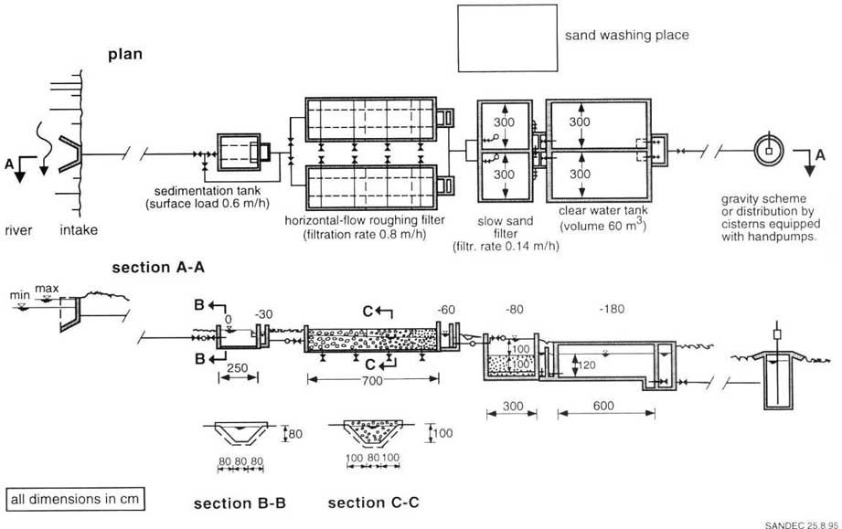
Fig. 20 Example of a Water Treatment
Layout
Fig. 15 on page Vl-1 illustrates different hydraulic layout
possibilities. On the raw water side, the water flows by gravity directly to the
treatment plant or, if pumped, preferably first to a raw water balancing tank.
After passing through the treatment plant it is stored in a reservoir and later
distributed to the consumers by a piped gravity scheme close to the houses.
In a semi-piped scheme, the water flows by gravity through the treatment
plant into the reservoir equipped with handpumps, or, as an extended
alternative, the reservoir is connected to a system of cistern located between
treatment plant and village. Treated water is now supplied by gravity to these
cisterns equipped with handpumps. Each cistern acts as reservoir and water
point.
Such distribution systems may increase sustainability and
reliability of a water supply as the energy supplied by the consumers when
operating the handpump keeps the water supply system running at low operating
costs and at village maintenance level. The proposed system of storage tanks
equipped with handpumps can best control excess water usage, prevent
contamination and avoid wastewater disposal problems.
However, the consumer may require higher service levels than the
aforementioned "handpump option". On the one hand, higher service levels run
parallel with increased water consumption and wastewater disposal problems, on
the other, collection of water charges may become easier if the distribution
level is shifted from public to individual supply.
Concerning the different service levels, the following per
capita daily water demand values are generally used:
|
supply with public handpumps |
q = 15 - 25 I/c.d |
|
supply with public standpipes |
q = 20 - 30 I/c.d |
|
supply with yard connections |
q = 40 - 80 I/c.d |
|
supply with multiple tap house connections |
q = 80 - 120 I/c.d |
The effective q values for the supply with public handpumps or
standpipes are greatly influenced by transport distance, ranging from a few
dozen to 300 and more metres. For yard and house connections, water use will be
influenced by the level and manner in which the water charges are levied (e.g.
as a monthly lump sum or on an effectively used water volume basis recorded by
water metres). Furthermore, use of drinking water for backyard garden irrigation
leads to an enormous water demand and should therefore be prohibited.

Fig. 21 Raw Water Supply and Flow
Control
|
The Handpump Handle Keeps the Water Supply
Operational
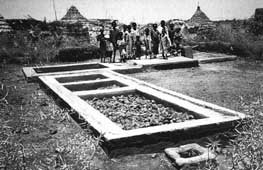
The Handpump Handle Keeps the
Water Supply Operational
A large number of irrigation canals supply water to the
Gezira/Managil zone where cash crops, such as cotton, corn and vegetables are
grown. The fertile soil and sufficient water drawn from the river Nile are the
base for profitable agriculture. However, the income of the farming community,
which has settled along the irrigation canals in modest straw huts, is very low.
Since malaria, bilharzia and diarrhoeal diseases are also widespread among the
population, the Blue Nile Health Project was launched to improve the health
situation of the people living in the project area.
Absence of infrastructure, energy and low income of the
population placed severe constraints on the water supply improvement scheme. The
villagers, which live in settlements of 200 - 500 people, drew their water from
the irrigation canals contaminated by human excreta. Use of groundwater drawn
from a well has always been favoured. However, since groundwater was often
unavailable, the polluted irrigation canal water had to be treated.
In the implemented standard design of the project area,
the water flows by gravity from the canal through a horizontal-flow roughing
filter and a slow sand filter into the clear water tank. A simple handpump was
installed on top of this tank to allow the drawing of treated water from the
installation. The operating costs are kept minimal and mainly used for new
handpump rubber seals which have to be replaced every two months and for filter
cleaning carried out by the community twice a year. The daily energy input of
the water drawers at the handle of the handpump keeps the system running and
provides clean water even to an underprivileged society. |
7. Roughing filtration application
7.1 Historic use
The natural water treatment potential was adopted long before
chemical water treatment methods, such as chlorination and flocculation,
were discovered and applied. Gravel and sand used as filter media are key
components in natural treatment processes. Although sand was able to
maintain its important role since the development of the first slow sand filters
at the beginning of the last century, the use of roughing filters was
successively replaced by chemical water treatment processes. A comprehensive
review of gravel filter application is far beyond the scope of this manual.
However, a few examples presented hereafter will document that the roughing
filter technology is an old water treatment process used in the past and
rediscovered in recent years.
Numerous castles and forts were constructed in Europe during the
Middle Ages. They were often located at strategically important points,
difficult to conquer and also to supply with water. Ingenious water supply
installations were therefore constructed. A good example is the former castle
of Hohentrins located on top of a steep rocky reef in the Swiss Alpine
valley of the river Rhine. During periods of war, the people who sought
protection in this castle depended on rainwater collected in the yard and stored
in a cistern. In this extensively used area, it was, however, not possible to
avoid water pollution caused by man and animal. Therefore, in order to treat the
water, a gravel pack was installed around the inlet of the cistern. This
is probably one of the first roughing filters used to treat surface water [31].
In 1804, John Gibb constructed the first water filtration
plant for a public water supply at Paisley in Scotland. ln order to pretreat
the muddy river water, John Gibb designed and constructed an intake filter
described as follows:
"Water from the River Cart flowed to a pump well through a
roughing filter about 75 feet long, composed of "chipped" freestone, of smaller
size near the well than at the upper end. This stone was placed in a trench
about eight feet wide and four feet deep, covered with '´Russian mats" over
which the ground was levelled." (cited from [1]).
The pretreated raw water was then lifted by a steam
engine-driven pump to a place 16 feet higher than the river from where it flowed
by gravity to the water treatment plant. This installation consisted of three
concentric rings each six feet wide and arranged around a central clear water
tank measuring 23.5 feet in diameter. The water flowed in horizontal direction
from the outer ring, which was used as settling basin, through the two other
rings towards the centre into the clear water tank. The two inner rings
contained coarse and very fine 9 ravel or sand as filter material respectively.
John Gibb applied, already then, the multi-stage treatment approach; i.e.,
the intake filter, the settling basin and the gravel filter were used as
pretreatment processes prior to sand filtration. Many other water treatment
plants in England followed the example of Paisley and applied coarse gravel and
slow sand filtration. In the last century, the general water treatment practice
in Great Britain comprised the use of multiple filtration in form of roughing
filters placed in front of slow sand filters. It was only in 1925 that rapid
sand filters were slowly introduced to increase the capacity of slow sand
filters. In the US, however, the clay content in the raw water prohibing
adequate slow sand filter operation was one reason for developing rapid sand
filters at the turn of the century.
Puech-Chabal filters, constructed in France in 1899 to
treat part of the water supplied to the city of Paris, are another example of
roughing filter application. The treatment scheme consisted of a series of
filters and cascades to treat turbid surface water. The water flowed through
four downflow roughing filters and one so-called prefilter before being treated
by a finishing filter. Cascades were used to aerate the water in between the
different filter stages. The filter material decreased successively in size, and
the filtration rate was also reduced from filter to filter. The Puech-Chabal
treatment system was used extensively in Europe. By 1935,125 plants were built
in France, nearly 20 in Italy and some in other European countries [1].
After some time, the roughing filters were virtually
converted into rapid or mechanical filters. Coagulation, combined with
sedimentation, was introduced as a pretreatment method and, more recently,
direct filtration (coagulation, flocculation and solids removal are carried out
in filter units only) replaced the prefilter technology. In recent years,
however, the roughing filter technology has been revived in Europe through
its use in artificial groundwater recharging plants. In the early 1960s, the
waterworks of Dortmund, Germany, constructed horizontal-flow roughing filters of
50-70 m filter length which are operated at about 10 m/h filtration rate [32].
The raw water falls over an aeration cascade, crosses a sedimentation trough
before entering the roughing filter at the top of the gravel bed. The filter
inlet zone is progressively impounded with increasing running time, and the
entrance area of the water thus slowly shifts in direction of the filter outlet.
After prefiltration, the water falls over a second cascade, percolates through
the sand filter bed and finally reaches the aquifer. Other waterworks in Europe
(e.g. in Switzerland and Austria) followed the example of Dortmund with modified
horizontal-flow roughing filter designs as shown in Fig. 22.
European rivers usually exhibit low turbidity, however,
filter operation is stopped during the short periods of high turbidity. A
continuous supply of water to the consumers is guaranteed by the use of the
aquifer's water storage capacity. In contrast to filter plants in moderate
climates, roughing filters in tropical countries usually have to handle raw
water of permanent or seasonable high turbidity. Since aquifers are often
unavailable due to unfavourable hydrogeological conditions, the water supplies
have to draw the water directly from surface water, treat it and supply it to
the consumer throughout the year and even during periods of extremely poor raw
water quality. Reliable operation is especially required during the rainy
season, at the beginning of the wet period when the risk of epidemic outbreaks
of diarrhoeal diseases increases as a result of rain washing poorly disposed
faecal material into surface waters, and later on to cope with heavy sediment
loads when the faecal pollution may be reduced by high dilution. Efficient and
reliable water treatment is nevertheless also required in the dry season when
surface waters in arid areas may discharge poorly diluted wastewater. The need
for reliable and simple water treatment processes initiated the development of
roughing gravel filtration which received considerable attention in recent
years. Studies on design and performance of prefilters functioning under
tropical water quality conditions have been, and are still being, conducted by
various research groups.

Fig. 22 Different Layouts of
Horizontal-flow Roughing
Filters
7.2 Development of roughing filters
Motivated by the simplicity of horizontal-flow roughing
filters, different institutions em barked on laboratory and field studies in
order to assess the potential of horizontal-flow roughing filters in reducing
the solid matter concentration of highly turbid surface water. In 1977, the
Asian Institute of Technology (AIT) in Bangkok, Thailand, conducted
laboratory tests with a prefilter composed of seven gravel layers [33]. Three
full-scale water treatment plants applying the AIT prefilter design were later
constructed in combination with slow sand filter units. The treatment plants,
monitored for about half a year, revealed a good performance of the prefilters
and enabled slow sand filter runs of several months [34]. These investigations
were, however, discontinued and, therefore, marked the end of the project in
Thailand. Since 1979, the Pan American Centre for Sanitary Engineering
(CEPIS/PAHO) conducted an experimental programme that concluded in a
comprehensive review and design manual introducing/he roughing filter technology
[35].
The University of Dar es Salaam, Tanzania, embarked on
laboratory filtration tests in 1980. Initially, investigations on vertical-flow
roughing filters revealed short filter runs of a few days only. Subsequently,
the horizontal-flow roughing filter concept was developed and the design tested
with a 15-m long open channel filled with three gravel fractions ranging in size
from 16-32, 8-16 and 4-8 mm. The laboratory tests clearly indicated that
significant solids removal is achieved only under laminar flow conditions, as
sedimentation is the predominant process in roughing filtration [36]. Field
tests were then conducted to assess the applicability of the horizontal-flow
roughing and slow sand filter treatment combination. The pilot plant
investigations compared the developed filter resistance of different slow sand
filters fed either with untreated or with prefiltered turbid river water. A
significant increase in slow sand filter runs was achieved with prefiltration.
The field tests revealed that horizontal-flow roughing filtration combined with
slow sand filtration could be a viable system for turbid surface water treatment
[37].
From 1982 to 1984, extensive filtration tests were conducted by
the Department of Water and Sanitation in Developing Countries (SANDEC),
formerly IRCWD, at the laboratories of the Swiss Federal Institute for
Environmental Science and Technology (EAWAG) in Duebendorf, Switzerland. A
model suspension of kaolin was used to investigate the mechanisms of
horizontal-flow roughing filtration. Two important laboratory test results
established that filter efficiency is hardly influenced by the surface
properties of the filter medium, and that filter regeneration can be enhanced by
drainage. The results of the research are summarised in a scientific paper [38],
and the more practical aspects on implementation of horizontal-flow roughing
filtration are compiled in a design, construction and operation manual [39]. In
a collaborative effort, the University of Surrey, the DelAgua Organisation and
CEPIS/PAHO developed and implemented vertical roughing filtration in Peru in
1985. Implementation and evaluation of horizontal roughing filters [12] were
extensively supported by SANDEC in subsequent years.
Financially supported by the Swiss Development Cooperation
(SDC), which already cofinanced SANDEC's laboratory tests, promotion and
dissemination of the horizontal-flow roughing filter technology started in
1986. Under the technical assistance of SANDEC, engineers of local institutions
designed full-scale demonstration plants in order to study this technology and
gain practical experience with the treatment process. Frequently, horizontal-f
low roughing filters were constructed in order to rehabilitate deficient slow
sand filter plants. In the past ten years, the promoted filter technology has
spread to more than 20 countries and, according to SANDEC's knowledge, over 80
horizontal roughing filter plants have been constructed during this period
[40]. Fig. 23 indicates the countries where these filters have been
constructed. Basic information on roughing filtration, as well as new approaches
and designs developed by local engineers and practical field experience with the
filter technology are presented in the following chapters of this publication.
Furthermore, several institutions conducted additional studies,
usually in the form of postgraduate research work [41, 42, 43, 44, 45, 11, 12],
on the horizontal-flow roughing filter process. The University of Dares
Salaam, Tanzania, the Tampere University of Technology in Finland, the
University of Surrey in Guildford, England, the International Institute for
Hydraulic and Environmental Engineering in Delft, the Delft University of
Technology in the Netherlands, and the University of Newcastle upon Tyne in
England, as well as the University of New Hampshire in Durham, USA
conducted, among other institutions, laboratory or field tests with roughing
filters. Furthermore, laboratory tests on pebble bed filtration were carried out
at the Imperial College in London, England [46].
Different pretreatment methods, including horizontal-flow
roughing filtration, are currently field tested on a comparative basis by an
extensive research programme in Cali, Colombia, where the Instituto de
Investigaci�n y Desarrollo en Agua Potable, Saneamiento B�sico y Conservaci�n
del Recurso H�drico (CINARA) investigates, in collaboration with the
International Water and Sanitation Centre (IRC) in The Hague, The Netherlands,
and different other international technical institutions and supporting
agencies, the potential to optimise and simplify pretreatment processes [47].

Fig. 23 Geographical Distribution of
Horizontal-flow Roughing Filter Use
|
"Hot Water" for Filter Promotion
Sadig, Manager of the Water Supply Programme, can be proud
of the progress of his project. A map on the wall behind his desk is covered
with small pins indicating the location of the filter projects. All the pins are
arranged along irrigation canals used as raw water source for the water supply
systems of the small villages. The programme has started three years ago and
since then over 30 schemes have been put into operation. A success which is not
shared by the progress of other development projects carried out in the
region.
The pins on the map were of different colours; i.e., red,
green and blue depending on the year of construction. The pins were not evenly
arranged on the map. Some were scattered along the canals, but an important
number of pins were clustered around a limited area of the map. All but one pin
were green and blue, the single red pin was marked "Hariga", the name of the
village.
Neither the project office, nor the workshop or the
training centre were located near Hariga. Nonetheless, this spot seemed to be
the focal point of the project. A large smile covered the manager's face when he
revealed the secret of Hariga. The village was well-known to everybody for its
illegal production of alcohol. Customers from neighbouring villages came to
purchase the distilled alcohol at night and the purchase was quite often
combined with cheerful social activities. Since distillation was not yet quite
refined, the alcohol had to be diluted with clear water produced by the recently
installed filter. The nocturnal customers saw the treatment plant, enjoyed the
crystal clear water and wanted a similar installation in their village.
Sadig deliberately selected Hariga as demonstration site
to introduce the new treatment process, as Hariga means hot water in the local
language ..... |
| | | Surface Water Treatment by Roughing Filters - A Design, Construction and Operation Manual (SANDEC - SKAT, 1996, 180 p.) | | | Part 2: Design, construction and operation of roughing filters | | | 8. Classification of roughing filters | | | 9. General aspects of roughing filter design | | | 9.1 Main features | | | 9.2 Basic filtration theory | | | 9.3 Design variables and guidelines | | | 9.4 Flow and headloss control | | | 9.5 Filter drainage system | | | 9.6 General design aspects | | | 10. Detailed filter design | | | 10.1 Intake Filters | | | 10.2 Dynamic filters | | | 10.3 Vertical-flow roughing filters | | | 10.4 Horizontal-flow roughing filters | | | 11. Roughing filter efficiency | | | 11.1 Practical experience | | | 11.2 Pilot plant tests | | | 12. Selection criteria for roughing filters | | | (introduction...) | | | 12.1 Raw water quality as selection criteria | | | 12.2 Layout and operational aspects as selection criteria | | | 13. Construction of roughing filters | | | (introduction...) | | | 13.1 Filter box | | | 13.2 Filter material | | | 13.3 Inlet and outlet structures | | | 13.4 Drainage system | | | 13.5 Gravel and sand washing facilities | | | 14. Operation and maintenance of roughing filters | | | (introduction...) | | | 14.1 Caretaker training | | | 14.2 Treatment plant commissioning | | | 14.3 Flow control | | | 14.4 Water quality control | | | 14.5 Filter cleaning | | | 14.6 Filter maintenance | | | 15. Economic aspects | | | (introduction...) | | | 15.1 Construction costs | | | 15.2 Operating and maintenance costs | | | 15.3 Overall costs of water supply schemes | | | 16. Design examples | | | (introduction...) | | | 16.1. Treatment of an upland river | | | 16.2 Treatment of a lowland stream | | | 16.3 Treatment of reservoir water | | | 16.4 Rehabilitation of a slow sand filter plant | | | 16.5 Standard designs for compact water treatment plants | | | 17. Final remarks | | | (introduction...) | | | References | | | Abbreviations |
|
Surface Water Treatment by Roughing Filters - A Design, Construction and Operation Manual (SANDEC - SKAT, 1996, 180 p.)
Part 2: Design, construction and operation of roughing filters
8. Classification of roughing filters
As shown in Table 1, filters can be classified according to
filter material size and filtration rate into the following categories: rock
filters, roughing filters, rapid sand filters and slow sand filters. Roughing
filters, using mainly gravel as filter medium, are operated without chemicals
and do not require sophisticated mechanical equipment for operation and
maintenance. Nevertheless, their design and application vary considerably.
The different roughing filter types are classified according to:
- location within the water supply
- scheme main
application purpose
- flow direction
- filter design
- filter cleaning technique
Construction of infiltration galleries in the river bed
or next to the river embankment is an old technique used to draw surface water
and pretreat it at the same time. Infiltration galleries basically consist of an
excavated trench filled with gravel and sand layers surrounding a perforated
pipe. However, construction work in water bearing aquifers might prove difficult
unless extensive alluvial deposits and high seasonal flow variations prevail as
may be the case in South-East Asia. There, the infiltration gallery could be the
inlet technology of choice as it is almost maintenance free and may easily be
installed during the dry season, provided the aquifer characteristics prevent
clogging as well as breakthrough of fine material. Maintenance and cleaning of
infiltration galleries are hardly possible unless installed in the river banks
or in the bed of irrigation canals where the flow can be regulated or even
interrupted. Such flow regulations allow a controlled operation, protect the
installed gravel layers from being washed away, and enable maintenance work,
e.g. cleaning or replacement of the filter layer.
Table 1 Filter Classification
|
Filter Type |
Size of Filter Material dig [mm] |
Filtration Rate VF [m/h] |
|
rock filter |
> 50 mm |
1 - 5 m/h |
|
roughing filter |
20 - 4 mm |
0.3 - 1,5 m/h |
|
rapid sand filter |
4 - l mm |
5 - 15 m/h |
|
slow sand filter |
0.35 - 0.15 mm |
0.1 - 0.2 m/h |
However, due to the limited application and briefly mentioned
operational inconveniences, infiltration galleries will not be further presented
in this manual. Intake and dynamic filters are usually the first
components of a treatment scheme. Similar to infiltration galleries, their
structure often forms part of the water intake installation. Intake filters are
used as first treatment step, mainly for separation of solids. The reduced
solids concentration in the pretreated water allows a more economical layout and
operation of the subsequent filter units. Dynamic filters are applied to
safeguard the treatment plant from sudden solids concentration peaks. Hence,
they are usually used not so much for water quality improvement, but to protect
the treatment plant from heavy silt loads and cumbersome filter cleaning work.
Roughing filters are generally located at the treatment
plant and used as last pretreatment process prior to slow sand filtration. These
filters can be operated either as upflow, downflow or horizontal-flow filters.
The different gravel fractions of roughing filters are installed either in
separate compartments and hence operated in series, or the differently sized
gravel is placed in succeeding layers in the same compartment.
Filter cleaning, which is carried out manually or
hydraulically, is dependent on the pattern of the retained solids in the filter.
Intake and dynamic filters separate the solids usually within the inlet zone of
the filter and thus act as surface filters. The relatively fine gravel of
these filters is cleaned manually by scouring the top of the filter with a
shovel or rake, and flushing the resuspended solids from the filter bed.
Roughing filters containing differently sized filter material act as deep bed
filters and allow deep penetration of the solids into the filter medium.
Removal of the accumulated solids is carried out by periodic filter flushing.
Roughing filters might gradually get silted up if the retained solids are not
completely removed by hydraulic filter cleaning. Such undesirable filter
clogging calls for tedious manual cleaning and should thus be avoided whenever
possible by regular and efficient filter drainages. Construction of shallow beds
in upflow roughing filters minimises construction and maintenance work and,
finally, also manual cleaning. However, such shallow upflow roughing filters
should be used only with raw water of moderate turbidity.
A general layout of different prefilters is given in Fig. 24,
the main differences in use and configurations of the prefilters are summarised
in Table 2, and the detailed filter design and operation explained in Chapters
10 and 14 respectively.
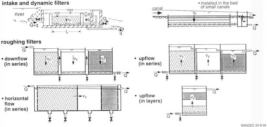
Fig. 24 Classification of Prefilters
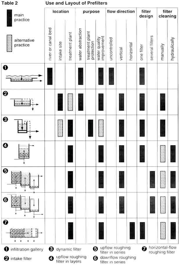
Table 2 Use and Layout of Prefilters
|
Children as Promoters of an Infiltration Gallery
Project

Children as Promoters of an
Infiltration Gallery Project
Different East African countries suffer from civil war.
This situation causes enormous misery and drives thousands of people away from
their native villages and towns. They become helpless refugees frying to escape
cruelty and starvation. The homeless often settle next to larger settlements
where they try to survive, as in the case of an old tracing and border town. In
the last few years, the population of this town has rapidly grown to 15,000
people due to refugees and migrants. Owing to the totally inadequate water
supply and sanitation facilities, the town council faces enormous problems which
could suddenly lead to cholera epidemics.
The town uses the rather large river as its water supply.
The raw water used to be pumped to a hill some 1500 m away where a compact
treatment plant, donated by a European aid agency, was never put to use due to
its high degree of sophistication. The paint is peeling off the containers and
some of the moving parts are gradually disappearing. This is why the population
collects water from the river heavily polluted by human excreta.
Mesfin, a dynamic local sanitary engineer, aware of the
inadmissible and dangerous situation, approached external support agencies and
asked them to finance a water supply project in his town. He invited desk
officers from the capital to the town and went with them to the bridge across
the river. From there, the delegation saw children digging a hole into the river
bed. Clear water started to seep into the shaft when the hole reached a depth
equal to the length of a child's arm. This gave Mesfin the idea of installing an
infiltration gallery in the 2-m deep gravel and sandy river bed and of
constructing a pumping platform next to the river bank. After witnessing this
simple display, the delegation approved Mesfin's unconventional but appropriate
project.
A year later the project was inaugurated by the officials
from the region and invited guests from the capital. The 500 NTU turbidity of
the raw river wafer was reduced to 15 NTU by the infiltration gallery, a value
similar to the one achieved by the children and their hole. |
9. General aspects of roughing filter design
9.1 Main features
Different installations are required for controlled and adequate
filter operation and maintenance. However, the main part of the filter is the
section containing the filter material. A filter comprises the following six
elements as schematically illustrated in Fig. 25:
- inlet flow control
- raw water
distribution
- actual filter
- treated water
collection
- outlet flow control
- drainage system
The inflow to a filter has to be reduced to a given flow
rate and maintained thereafter at this rate as constant flow conditions are
essential for efficient filter operation. In order to simplify flow control
during operation, the adjusted constant flow rate can remain unchanged even
during filter cleaning. However, intake filters require a controlled increase of
the flow rate in order to provide sufficient washwater to flush the resuspended
solids out of the filter surface.
The raw water distribution on a filter should be
homogeneous to achieve uniform flow conditions in the filter bed. Therefore, the
flow emerging from a pipe or a channel ought to be evenly distributed over the
entire filter surface. Submerged filter beds, inlet weirs covering the full
filter width, or perforated walls supplying the entire filter cross section are
used for this purpose. To avoid scouring effects of the filter material, the
hydraulic energy of fast flowing water has to be reduced by baffles positioned
in the inlet zone. For the same purpose, concrete slabs or large flat stones
should be placed on top of the filter material next to overfalls.
The actual filter consists of a watertight structure
containing filter material. The shape of the filter box is normally rectangular
and the walls vertical. However, depending on the local construction techniques,
circular tanks and inclined walls may also be built. Round river bed gravel or
broken stones with sharper edges are generally used as filter material, although
any type of inert material resistant to mechanical forces, insoluble, and not
impairing the water quality with respect to odour or colour, can be used as
filter material.
Collection of the treated water also has to be uniform
over the entire filter bed. Uneven water abstraction would reduce the overall
filter efficiency and create undesirable hydraulic short circuits. Provision of
a free water table on top of the filter bed is the best option to achieve even
collection of the treated water for upflow filters, or the construction of a
false filter bottom (see Fig. 47) for downflow filters. A second but less
favourable option is the installation of perforated pipes in downflow filters.
For horizontal-flow filters, construction of a perforated wall in the outlet
chamber is necessary for even abstraction of the treated water.
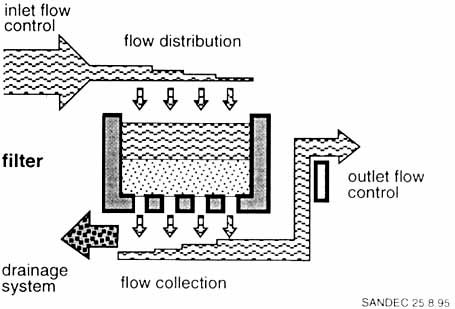
Fig. 25 Main Features of a Filter
The outlet flow control prevents the filter bed from
drying out. Hydraulic cleaning of a dried up roughing filter filled with
accumulated solids is a very difficult if not impossible task. Therefore, all
roughing filters must be operated under saturated conditions. A weir or a raised
and aerated effluent pipe maintains the water above the filter bed level.
Furthermore, a V-notch weir might be installed to allow flow rate measurements
at the filter outlet.
The drainage system of roughing filters serves two
purposes: it is used for hydraulic filter cleaning and allows complete during
maintenance or repair work. Hydraulic filter bed cleaning calls for high
discharge rates and, therefore, requires rather large pipes and fittings. For
complete water removal, additional but smaller drains in inlet and outlet
compartments can be installed.
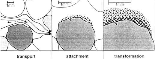
Fig. 26 Solid Separation Mechanisms
in Roughing
Filters
9.2 Basic filtration theory
The following explanations aim at providing some information
about the filtration mechanisms and at elucidating the process in more details.
Removal of suspended solids by roughing filters is a rather complex process
that includes sedimentation, adsorption and biological as well as
biochemical activities. Basically, as illustrated in Fig. 26, solid particles
have to be transported to a surface and remain attached to that
surface before they are possibly transformed by biological and
biochemical processes. The latter are also important for the removal of
dissolved impurities.
Let us now follow the path of a small 4 µm (0. 004 mm)
clay particle through a roughing filter. Please note that the following
described journey of our clay particle through a roughing filter is not a
science fiction story but a popular description of particle removal mechanisms
taking place in roughing filters. Annex 4 provides additional analytical details
of the processes described more scientifically in [38]. The small clay particle
is exposed to different transportation, attachment and transformation
mechanisms.
Transportation mechanisms
Screening removes particles larger than the pores of the
filter bed. The smallest pore sizes are roughly one sixth of the gravel size.
Since our clay particle is travelling unhindered through the
large pores of the coarse, medium and even fine filter gravel, as shown in Fig.
27, it will never be retained by screening mechanisms.
Sedimentation separates settleable solids by gravity. The
settling velocity is influenced by mass density, size and shape of the particle,
as well as by viscosity and hydraulic conditions of the water.
Let us now assume that our clay particle has reached the
finer gravel fraction of our roughing filter operated at 0.5 m/h filtration
rate. Even at this low filtration rate, the time of flow through a pore of 4 mm
length and 1.25 mm height is only 10 seconds whereas the settling velocity of
the clay particle amounts to 0.01 mm/s. Hence, our clay particle would need 125
seconds to overcome only half of the pore height and will, therefore, hardly
touch the surface of a gravel grain but continue to drift deeper into the filter
bed as shown in Fig. 28.
Interception is described as the process which enhances
particle removal through gradual reduction of the pore size caused by
accumulated material.
Our floating clay particle wants to settle on the filter
medium and desperately calls his friends already resting on the gravel surface
for help. He knows that hundreds of million of colleagues have already entered
the roughing filter before he started his hopeless journey, and that the filter
load (weight of accumulated solids per unit filter volume) has reached a value
of 5 g/l. However, the initial filter bed porosity of 35% can only be reduced by
0.25% if his resting clay particle colleagues are packed like sardines.
Fortunately, they are building up on the gravel grains and form structured
pyramids, thereby increasing the occupied filter volume by a factor 10. As
illustrated in Fig. 29, they are thus able to reduce porosity by 2.5%. However,
our desperate clay particle is missing his colleagues since the settling
distance is still far too big.

Fig. 27 Screening

Fig. 28 Sedimentation
Fig. 29 Interception

Fig. 30 Hydrodynamic Forces
Hydrodynamic forces are responsible for the water in the
filter to flow continuously through the pore system and not to turn stagnant.
The water has to surround each single gravel grain on its way through the
filter. The flow lines are, therefore, not straight but curved around the gravel
grains. The water has to change even its velocity, since restrictions require
flow accelerations, and large pore volumes even force the water to take a short
rest.
As illustrated in Fig. 30, our old clay particle is also
exposed to this flow pattern and hydraulic shear forces which drive him on a
twisted trail. He gets thrown off track by these hydrodynamic forces that lead
him into a filter compartment with stagnant water where he has time to settle
and join his waiting colleagues.
Hence, our clay particle had to be grateful to the flow
pattern and hydrodynamic forces which transported him closer to the filter
grains or to a quiescent zone where he could settle on the filter material. On
his way through the filter he noticed that some very tiny particles, known as
colloids, had slightly changed their direction when compared to the bulk of the
solids, and had diffused due to molecular forces (Brownian movement) in some
other directions. However, these forces did not affect him in the least.
Attachment mechanisms
Our clay particle, glad to have escaped the flow is still
exposed to the water current which tries to drag him away. In this delicate
situation, the clay particle can count on the help of his colleagues and on the
support of the grain surface.
Mass attraction and electrostatic force - a combination
of these two forces is frequently called adsorption, enable the particles to
keep in contact with other solids and the filter material. Mass particle
attraction (van der Waals force) and the attraction between opposite
electrically charged particles (double layer forces) very much decrease with
increasing distance between the particles. In roughing filters, these forces are
important only to hold the settled particles together on the grain surface.
Biological activity will develop in the filter when
particles of organic origin are deposited on the filter material. Bacteria and
other microorganisms will form a sticky and slimy layer around the gravel or may
build a large chain of organic material floating in the pores of the filter
material.
This biological microcosm is alive. A forest composed of
microbes is inhabited by monsters in the form of larvae and smaller
microorganisms such as bacteria. The forest is subjected to constant changes,
the micro-inhabitants are eaten up by their macro-residents, thus making a
prediction of the behaviour pattern almost impossible. Particles readily adhere
to this organic material and are retained in the filter.
Electrostatic and mass attraction as well as biological
activity allow particles to remain on the deposited material.
Transformation mechanisms
As time goes by, new particles settle on top of our small
clay particle and slowly turn it into a firm structure of accumulated material.
However, he is no longer alone with his clay particle colleagues since other
material of organic origin and biological matter have started to invade the
pyramid-like structure. He also notices the change in water quality within the
structure as he is no longer exposed to fresh water flowing on the surface of
the accumulated material.
Biochemical oxidation starts to convert organic matter into
smaller aggregates and finally into water, carbon dioxide and inorganic salts.
Also part of the dissolved matter is subjected to these chemical and biochemical
reactions. Turbidity and colour also undergo changes, while iron and manganese
traces are precipitated and removed.
Microbiological activity also play an important part in
roughing filters. The back of our old clay particle started to itch and he
realised that three tiny microorganisms had attached themselves to his surface.
He then remembered that some faecal coliforms, which were tired of swimming
around, had asked him for a lift before entering the roughing filter He /lad
agreed to give them a ride and they therefore started their journey through the
filter like boat-people on the back of the clay particle. They also remained
together as the particle settled on the filter material. But as time went by,
these faecal coliforms started to starve and were attacked by other
microorganisms. It was their last twitch just before they passed away which
disturbed our clay particle colleague.
Hence, biologically active roughing filters are not only
efficient in removing solid matter but also in improving significantly the
chemical and microbiological water quality.
The "1/3 - 2/3 Filter Theory"
Our old clay particle still did not feel comfortable even
after the death of the three faecal coliforms as he was embedded in a large clay
deposit. Conversation with his colleagues became boring and he started to ponder
on how to change his present unsatisfactory situation. He remembered seeing a
lot of clay fellows sitting cheerfully on the larger grains while he had to
travel through the filter uncomfortable and squeezed in. Thanks to his quick
mind he developed the "1/3 - 2/3 filter theory".
He knew by experience that a particle can bypass a gravel
grain either on the left or on the right or settle on its surface. Hence, the
chances to fall on the grain is 1/3. However, the game continues as there is a
second, third and many other gravel grains to settle on. At this point our clay
particle started making some calculations. He assumed that if about 300 clay
particles enter the filter 100 clay particles would settle on the first layer of
grains and 200 clay particles would have to continue their journey to reach the
second layer of grains. Here again, 1/3 or 67 particles would attach themselves
to the second line, and 2/3 or 133 particles remain in the water flow.. The next
line of particles would be split in 44 to 89 particles. He continued his mental
arithmetic and was glad that someone was writing it down in Annex 4.
Proud of himself, the clay particle evaluated his calculation
and came to the conclusion that 90% of the 300 particles which enter a filter
are removed already after the 5th or 6th gravel layer. The remaining 10% have to
travel through another five to six gravel layers in order to achieve a 99%
particle separation. Hence, compared to an efficiency of only 1.5% per layer in
the second filter section, the first part of the filter is apparently more
efficient in particle removal, since every layer of this filter section retains
about 16% of the particles. The following filter sections are obviously less
efficient in particle removal. However, our clay particle found it hard to
believe that a gravel grain in the inner part of the filter with the exact same
size and shape as a gravel grain located in the filter inlet should be less
efficient in particle removal. He then remembered that filter efficiency is
dependent on particle concentration: the higher the concentration of impurities,
the greater the apparent efficiency.
Nevertheless, the clay particle was not yet satisfied with
his filtration theory as it would mean that the number of particles found on the
gravel would continuously decline on his journey through the filter.
Nevertheless, he remembered that the has encountered a sudden increase of
settled particles at some specific points in the filter. He quickly concluded
that these places were identical with the changes in the gravel fractions.
Furthermore, he recalled that his finer clay particle fellows did not have the
same settling pattern; i.e., they penetrated deeper into the roughing
filter.
And finally he had the feeling that the settling conditions
were not always the same. There was a crowd at the filter inlet and it was hard
to find a free space to rest. However, the inner filter part provided more
space, and settlement on the gravel grains was even supported by a sticky layer
built on the gravel surface. Hence, filter efficiency not only depends on the
size of the filter medium and particles, but also on the actual filter load and
biological filter activity.
Our clay particle was pleased that his filter theory and
conclusions were endorsed by some researchers carrying out filtration tests.
Their results and developed correlations between the different parameters on
horizontal roughing filtration are summarised in Annex 4. However, based on his
own experience and reflections, our small filtration expert was convinced that
this filter theory is basically also valid for upflow and downflow roughing
filters. Hydrodynamic forces are present in all roughing filters where quiescent
conditions allow particles to settle. Nevertheless, he was frustrated that his
"1/3 - 2/3 filter theory" did not fit this ratio. Recorded filter efficiencies
are much smaller on account of the numerous flow lines curving around the gravel
grains.
Sudden liberation
Our puzzled clay particle became aware that his environment
was deteriorating during his reflections on filtration. Together with his
colleagues he was densely packed in a structure made of decomposing organic
matter and hungry microorganisms. The water around them was also foul-smelling.
However, this liquid hardly mixed with the water that was flowing gently at a
very constant rate and under laminar flow conditions through the filter. The
clay particle had the strong urge to dive into this fresh water, or even to swim
away.
All of a sudden, the quiescent and dull conditions stopped.
The filter was filled with tremendous noise which felt worse than a giant
earthquake. The water was shooting downwards through the gravel to the filter
bottom, and all the clay particles were anxiously holding each other. A side of
his structure was flushed away. Our terrified particle then saw a clump of
particles roll down like an avalanche. The dragging forces grew stronger, his
structure collapsed and then everything went very fast. Under very turbulent
flow conditions, he was flushed to the filter bottom, pressed through a pipe
where a valve nearly broke his neck, and was finally discharged into a lagoon.
Our old fellow gained his liberty and felt like a new-born. However, he was not
used to the bright sunshine and decided to settle again, but this time under
different conditions.
Closing remark: since the complex mechanisms of hydraulic
filter cleaning are not yet fully explored, our clay particle had no time for
further philosophical contemplation on this matter. This is where our excursion
through the basic filter theory comes to an
end.
9.3 Design variables and guidelines
The main objective of roughing filters is the reduction of solid
matter in the raw water from a specific, in many cases however unknown
concentration, to a level which allows a sound slow sand filter operation. A
turbidity value of about 10 20 NTU, or a suspended solids concentration of 2 - 5
mg/l, is generally considered an adequate pretreated water standard for slow
sand filtration. Furthermore, since the roughing filters have to treat a certain
volume of water per day, a reasonable operational period is necessary between
two filter cleanings. Explicitly, roughing filters have to meet the following
three design targets:
- reduce turbidity and suspended solids concentration by DC
(mg/l) to a level required for adequate slow sand filter operation
- produce a specific daily output Q (m³/d)
- allow adequate operation during a determined filter running
period Tr (days or weeks).
Filter design has to meet these targets and is defined by the
following six design variables which can be selected within a certain
range:
- filtration rate or filter velocity vF
(m/h)
- average size dgi (mm) of each filter
medium
- individual length Ii(m) of each specific filter
medium
- number ni of filter fractions
- height H
(m) and width W (m) of filter bed area A (m²).
Filtration rate VF generally amounts to 0.3 -1
m/h. Filters are occasionally operated at a filtration rate of up to 1.5-2
m/h or even 9 m/h as in intake and dynamic filters. However, the applied
filtration rate significantly influences filter performance although removal
efficiency does not seem very much affected in between varying filtration rates
of 0.3 and 0.6 m/h [48]. Filtration rate or filter velocity expressed in (m/h)
is defined as the hydraulic load (m³/h) applied to the filter and divided
by the area (m²) of the filter bed perpendicular to the flow direction.
Table 3 Gravel Fraction Sizes for Roughing Filters
|
Filter Material |
Size of Filter Material dg [mm] |
|
Characteristics |
1st Fraction |
2nd Fraction |
3rd Fraction |
|
coarse filter |
24 - 16 |
12 - 18 |
8 - 12 |
|
normal filter |
12 - 18 |
8 - 12 |
4 - 8 |
|
fine filter |
8 - 12 |
4 - 8 |
2 - 4 |
Size dgi of the filter material usually ranges
between 20 and 4 mm. The gravel should be rather uniform to achieve large
porosity. The uniformity coefficient U, defined here as quotient between the
largest and smallest size of a filter fraction (U = dgi max/dgi
min), should be in the order of 2 or less. Filter medium fractions as
listed in Table 3 would meet the recommended uniformity.
Since length Ii of the filter material is
dependent on the filter type, it may vary greatly. Dynamic and intake
filters acting as surface filters require a smaller filter depth of about 40 -
60 cm, compared to roughing filters operated as deep bed filters. The depth of
upflow and downflow roughing filters is limited by structural constraints,
however, it is generally between 80 and 120 cm. The length of horizontal flow
roughing filters is, in this respect, not limited. However, overall length
normally lies within 5 and 7 m.
Number ni of filter fractions is also dependent on
filter type. Surface filters might only need one fraction whereas roughing
filters are usually composed of three gravel fractions. The required overall
filter length can substantially be reduced with the use of differently graded
filter fractions as illustrated in Fig. 31. The bulk of the solid matter is
removed by the coarse filter fraction, the medium sized gravel has a polishing
effect, and the finest gravel ought to remove only the remaining traces of solid
matter. Therefore, individual filter length li of roughing filters
are often designed in a 3:2:1 ratio.

Fig. 31 Turbidity Reduction along a
Roughing Filter
Height H (m) and width W (m) are dependent on structural and
operational aspects. Shallow structures of about 1 - 2 m are recommended to
avoid problems with respect to water tightness. In view of a possible manual
filter cleaning, 1-m deep structures are even recommended for easy removal of
filter material. The width of the filters should also be limited to allow
efficient hydraulic cleaning and avoid washwater disposal problems. Therefore,
filter width should generally not exceed 4 - 5 m, and filter surface area A for
vertical flow filters should not be larger than 25 - 30 m² or 4 - 6
m² (cross section area) for horizontal-flow roughing filters. Since
these recommended maximum sizes limit hydraulic filter capacity, several filter
units operated in parallel are required to meet the requested treatment plant
output.
Construction of at least two parallel filter units is anyhow
advisable to allow continuous treatment plant operation even during major
maintenance and repair
work.
9.4 Flow and headloss control
The hydraulic conditions in roughing filters are determined
by the filtration rate VF (m/h), calculated as flow rate Q
(m³/h) divided by the active cross-sectional filter area A (m²), e.g.:
VF (m/h) = Q (m³/h) / A (m²)
For adequate filter performance, flow control is essential
and must meet the following targets:
- maximum flow through the treatment plant should be
limited in general, and through the filter units in particular
- total flow should be distributed evenly over the
parallel running filter units
- controlled water levels should be maintained within the
filter units.
Weirs, overflow pipes and valves are used to control the flow
through the treatment plant and the different filter units. Maximum flow
through the treatment plant is limited by an overflow generally located at the
intake. At the treatment plant, the flow is equally divided by a distributor box
or channel into the different filter units. The simplest flow control device
is a V-notch weir. Finally, maximum flow through the filter unit is limited
by an overflow located upstream of the V-notch weir.
The outlet structure controls the water level in roughing
filters. Installation of a V-notch weir to maintain a fixed water level is the
simplest flow control option. Even a normal effluent pipe can keep this water
table at a constant level. However, such an effluent pipe, without weir but
connected to adjacent pipe installations, does not allow discharge measurements
necessary for detection of possible leaks in the filter structure.
Filter resistance increases with progressive filter operation.
Final headloss in a roughing filter is usually small; i.e., 10 to 20 cm, or 30
cm at the most. Headloss variation in the filter can be recorded by the water
level in the inlet filter compartment. A general layout of inlet controlled
filter is illustrated in Fig. 32. More details on discharge measurements are
contained in Annex 2.
A variable water level on the effluent side is achieved
with the installation of a manually operated valve, a self-regulating floating
weir or a constant flow device as suggested in [49]. However, since final
headlosses for horizontal-flow roughing filters are relatively small, use of a
variable effluent level is not recommended.
Fig. 33 contains the main details of self-regulating flow
rate devices. Such installations are useful to maintain a constant flow
throughout the treatment plant in pumped raw water supply schemes,
particularly at night, provided a raw water balancing tank is installed for
continuous raw water supply.

Fig. 32 Layout of an Inlet-Controlled
Roughing
Filter
9.5 Filter drainage system
Accumulation of large volumes of solids in the filter media
decreases filter porosity and ultimately also filter efficiency and increases
filter resistance. To maintain adequate filter performance and limit filter
headloss, periodic removal of the accumulated solids from the filter media is
essential.

Fig. 33 Layout of Flow Rate
Controlling Devices
Roughing filters are cleaned either manually or hydraulically.
Manual filter cleaning (excavation, washing and refilling of the filter media)
is labour-intensive and cumbersome. Therefore, hydraulic filter cleaning
plays a key role in long-term and efficient roughing filter operation.
Hydraulic filter cleaning entails fast filter drainage of the
accumulated solids, which are flushed down to the filter bottom, dragged to the
drainage system and washed out of the filter. The following are most
important design variables for hydraulic filter cleaning:
- filter drainage velocity vd (m/h)
-
inlet area Ad of the drainage system
- horizontal distance
Ld (m) between the drains or openings in the filter
bottom
- washwater volume Vw
- cleaning frequency
1/Tr or filter running period Tr.
Filter drainage velocity is identical with the dropping rate of
the water table in the filter. High initial filter drainage velocity
vd is recommended for efficient cleaning. Turbulent flow
conditions are absolutely necessary for resuspension and transport of the
accumulated solids through the filter. Therefore, a drainage velocity of at
least 30 m/h, or preferably 60 - 90 m/h, is required for efficient hydraulic
cleaning.
Maximum drainage rate velocity is very much influenced by
minimum cross section area avail able for washwater flow. The cross section of
the drainage pipes constitutes a bottleneck, the other limiting factor is the
overall inlet area Ad of the drainage system, which should be
designed as large as possible. Perforated false filter bottom systems
provide a larger inlet area than a perforated drainage pipe system.
After having been flushed to the filter bottom, the resuspended
solids have to be transported to the inlet of the drainage system. The
horizontal distance Ld between the openings of the drainage system
should be as small as possible to prevent gradual accumulation of sludge at
the filter bottom. Here again, the installation of a false filter bottom is
recommended since the washwater can be collected more evenly than in a
perforated drainage system, which should be installed with a small horizontal
distance Ld of maximum 1 - 2 m between the drains.
Hydraulic filter cleaning is carried out with the washwater
volume Vw stored in the roughing filter. Normal filter operation
is interrupted and the drains opened. Hence, compared to rapid sand filters,
hydraulic roughing filter cleaning does not require additional equipment, such
as backwash pumps or even air compressors. To prevent loss of washwater, fast
opening valves and gates are necessary to make best use of the washwater
stored in the filter bed. Since such devices of relatively large diameter (about
150 - 250 mm) are rather expensive, alternative installations, as presented in
Fig. 34, have been developed by local institutions. Fast opening devices must
be simple in design, sturdy and easy to operate as well as watertight.
Furthermore, they should be fitted with a closing device to save washwater
during drainage. Locally manufactured devices need to be carefully field-tested
prior to their use in full-scale filter units.

Fig. 34 Layout of Fast Opening
Devices for Filter Drainage
Cleaning frequency or filter running period Tr of
roughing filters is dependent on solid matter load and biological activity in
the filter. General recommendations are not possible since each filter
operates under specific local conditions. Nevertheless, periodic hydraulic
cleaning is advisable to prevent gradual accumulation of solids in the filter
that filter drainage cannot remove due to agglomeration and consolidation.
Cleaning frequencies could amount to once every one to two weeks during the
rainy season, and once every one to two months during the dry season. However,
very high solid loads with turbidities > 1000 NTU call for daily hydraulic
flushes. Furthermore, excessive biological activities could hinder efficient
hydraulic cleaning or affect taste and odour of the water. Such conditions would
also require frequent hydraulic cleaning. Research in the laboratory [11] with
biologically ripened roughing filters suggests that a drying period will have a
positive impact on hydraulic filter cleaning. However, this observation is in
contrast with the general recommendation on keeping roughing filters always wet.
Safe disposal of the washwater is important. Filter
flushing generates relatively large washwater volumes (up to 10 m³) within
a short time (about 1 - 2 minutes). To prevent erosion in steep regions,
intermediate storage in a small, separately constructed pond may be necessary.
Such an installation would allow gradual and controlled discharge of the
washwater in a water course or its agricultural use. Furthermore, the solids
washed out of the filter and settled in the pond are a valuable soil conditioner
and fertiliser.
The drainage system used for hydraulic filter cleaning might not
be designed to drain the entire filter structure. However, complete drainage is
required during maintenance and repair of the filter. Additional small
drainage installations are thus necessary for complete removal of the water
stored in the filter. For this purpose, small drainage pipes equipped with
taps or plugs can be used in large roughing filters. Small structures can,
however, be dewatered with buckets or a tube used as
siphon.
9.6 General design aspects
Treatment facilities have to be dimensioned for extreme
loads; i.e., in terms of solids removal for maximum solids concentration in
raw waters. However, it is preferable to pretreat the raw water in a sequence
of different treatment units. Gradual reduction of suspended solids,
turbidity or pathogenic microorganisms by a sequence of different pretreatment
units probably offers the most economic option with respect to investment and
operating costs. Small pretreatment units, such as intake filters or
sedimentation tanks, can significantly reduce solid matter concentrations or
turbidity peaks. Furthermore, cleaning of these installations is generally
easier than roughing filters. Hence, roughing filters should preferably not be
designed to handle maximum water peaks, but pre-conditioned water that has
already been subjected to pretreatment.
Filter length and permissible filter running period are
correlated. Horizontal-flow roughing filters in particular were originally
designed to provide a large silt storage capacity at low headloss, as filter
cleaning was carried out manually. Relatively important filter lengths of 9 to
12 m were the consequence of this original design approach, permitting filter
runs of several months, similar to those of well-operated slow sand filters.
However, importance and benefits of hydraulic cleaning have meanwhile been
recognised.
Current design practice tends to reduce filter lengths and
incorporate efficient hydraulic cleaning facilities. Regeneration of filter
efficiency through frequent hydraulic cleanings has to counterbalance shorter
filter lengths.
The use of smaller filter material can improve filter
efficiency. However, besides efficiency in suspended solids separation,
other criteria such as terminal headloss, filter running time and filter
cleaning aspects have to be taken into consideration. Use of only a uniform and
fine filter material allows sufficient pretreatment of the raw water, but at the
expense of high head losses, short filter runs and filter cleaning difficulties.
The roughing filter technology requires the use of coarse filter material
sizes between 20 - 4 mm graded in different fractions. However, the use of
filter material coarser than 20 mm with lower removal efficiencies is not
advisable as it would require longer filters to achieve the same treatment
efficiency. Furthermore, the filter material should not be smaller than about 4
mm to facilitate hydraulic filter cleaning. These recommendations are not
applicable to intake and dynamic filters as these operate differently. Since
intake and dynamic filters are basically surface filters, they require small
filter material sizes between 2 - 8 mm. These filters act as surface
filters, and their filter depth therefore has no great influence on the overall
efficiency.
Filtration rate greatly influences filter efficiency.
Sedimentation is the main solids separation process in roughing filters.
Therefore, roughing filters must be operated under laminar flow conditions to
achieve adequate solids removal efficiencies. Flow conditions are described by
the Reynolds Number. At a value of less than 10, laminar flow can be expected
(see also Fig. 35). As the Reynolds Number is directly proportional to the
filter material size, maximum allowable filtration rate for laminar flow
conditions will be determined by the coarsest gravel fraction in a roughing
filter. Hence, for optimum filter use, coarser filter material requires
smaller filtration rates. However, filtration rate can only partly be
increased by applying smaller filter material, as particle size distribution of
the solids and suspension stability also determine the fillers' solids
separation efficiency.
Fig. 35 Roughing Filter Efficiency in
Correlation to Flow Conditions
|
African Killer Bees Supported Sustainability
The rapid sand filters of Salaga, a district centre
located in West Africa, were never filled with filter media and the population
of the town was therefore exposed to unsafe water. The old treatment plant had
to be extended and replaced by an appropriate treatment scheme. Roughing and
slow sand filters were thus tested in a pilot plant shaded by a large baobab
tree. The location was chosen by the external experts suffering from the
Ghanaian sun. The pilot plant was constructed by the local water authority, and
the expatriates supervised the start of the field tests. However, African killer
bees also chose the same large baobab tree as their habitat and were very much
attracted by the white skin of the foreigners. Under remote supervision by the
expatriates, the field tests were continued by the local staff which gained
experience and confidence in a treatment scheme they wit/have to run in future
at full scare and without foreign assistance. Thus, the African killer bees
somehow contributed to developing local sustainability. |
10. Detailed filter design
10.1 Intake Filters
Intake filters are combined with water abstraction structures
and installed next to small and narrow river beds as illustrated in Photo 5
and Fig. 36. Intake filters are often used as first pretreatment unit in
a water treatment scheme. A small weir regulates the water level of the surface
water and channels part of the flow into an adjacent filter compartment. This
filter box is filled with two gravel layers. The top layer consists of
relatively fine gravel of less than six millimetres in diameter.
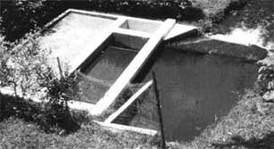
Photo 5 Example of an Intake Filter
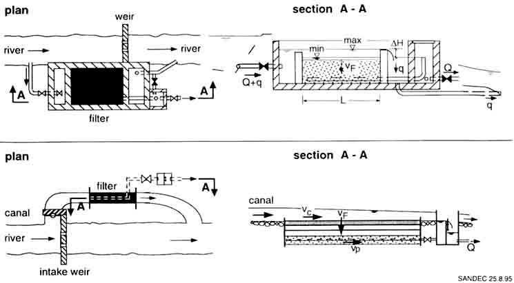
Fig. 36 Layout of Intake and Dynamic
Filters
The lower coarser gravel layer acts as filter support and allows
an even abstraction of the prefiltered water through perforated drainage pipes.
The abstracted raw water, after being distributed evenly by a small weir over
the entire width of the filter box, flows gently over the gravel bed surface.
Part of this water percolates through the gravel layers and the remaining water
is discharged over an outlet weir back to the river. Intake filters are
constructed along rivers and not directly in the river bed, as the filter
material would be washed out during periods of high river discharge.
Construction of a separation wall between river bed and filter box is
recommended to prevent the filter from being washed out.
Intake filters can also be installed in the bed of small
canals. Upland rivers with a steep river bed and a suitable topography might
allow the accommodation of a small diverting canal. The filter bed, comprising
different gravel layers, is installed over a small stretch in the canal. Part of
the canal water is filtered through the series of fine to coarse gravel layers,
while the remaining water is returned to the river. The prefiltered water is
collected by perforated drainage pipes laid at the bottom of the coarse gravel
layer, and the discharge rate regulated by a valve placed at the filter control
box. The flow velocity in the canal must be regulated by the canal's
intake structures to protect the filter bed from being washed out during periods
of high river discharge. The flow velocity in the canal should actually range
between 0.10 and 0.30 m/s to prevent fine matter from settling and remaining on
top of the gravel bed, and also to avoid fine filter material from being washed
out. This layout may also be applied to irrigation canals, provided they are
continuously supplied and regulated through out the year. However,
construction of intake filters along rivers is strongly recommended as these
filters allow a more reliable operation than intake filters installed in canal
beds.
Finally, "intake" filters may be located directly at the
treatment plant site and function as pretreatment facility. This particular
location is recommended in gravity water supply schemes with a raw water intake
located in a remote area of difficuIt access. Such a layout will facilitate
monitoring and regular filter cleaning.
Filtration rates of intake filters range between 0.3 and 2
m/h. However, significant solids removal rates can be expected only at
filter velocities smaller than 1 m/h, Design of the hydraulic structures should
be based on maximum filter resistance of 20 to 40 cm. This figure will not be
exceeded if regular filter cleaning, (e.g. once a week), is observed.
Relatively small filter material of less than 6 mm is used in
intake filters which act as surface filters as the solids mainly accumulate
on top of the filter bed. Since filter cleaning is carried out manually, the
different gravel layers might be disturbed and mixed up if filter material of
different sizes is used in intake filters. A filter cloth is sometimes placed
in-between the different gravel layers to avoid mixing of the filter fractions
and possibly reducing filter porosity and efficiency. However, coarser gravel
hardly contributes to solids removal, but allows an even abstraction of the
pretreated water. Nevertheless, regular filtered water collection is also
possible with a single filter bed layer, moderate filtration rates, medium-sized
filter structures and reasonable layout of the perforated drainage pipes. Design
guidelines are summarised in Fig. 37. Use of a single filter layer and false
filter bottom offers a favourable design alternative for intake filters, as
filter material mixing is no longer possible, and even abstraction of the
prefiltered water is guaranteed.
Fig. 37 Design of Intake and Dynamic
Filters
10.2 Dynamic filters
Dynamic filters protect the treatment plant units from high
turbidity peaks. Highly turbid surface water can quickly clog filters,
especially slow sand filters. Therefore, during periods of extremely high raw
water turbidity, the flow may be interrupted to reduce cumbersome filter
cleaning. Separation of solids is only of secondary importance in dynamic
filters.
Dynamic filter performance is, as described by its adjective,
dynamic. The water quality between filter inlet and outlet hardly changes during
periods of low raw water turbidity. During raw water turbidity peaks, however,
the quantitative change is drastic as no water is available in the filter
outlet! Dynamic filters act like turbidity meters connected to an
open-close valve; i.e., they rapidly get clogged when raw water of high
turbidity passes through the filter.
Dynamic filters are similar in layout to intake filters, but
differ in filter material size and filtration rate. Especially the gravel
size of the top filter layer is smaller; i.e., less than 6 millimetres in
diameter, while filtration rate is usually more than 5 m/h, Maximum available
headloss is still limited and ranges between 20 and 40 cm in spite of finer
filter material and greater filter velocity. Finally, the horizontal flow
velocity over the filter bed surface should be small or non-existent; i.e., less
than 0.05 m/s or nil, to prevent removal of accumulated silt during turbidity
peaks.
Dynamic filters are cleaned after each raw water turbidity
peak. Cleaning is also carried out manually and in the same way as in intake
filters. During periods of dynamic filter interruptions, treatment plant
operation is reduced (e.g. by declining filtration rate operation in slow sand
filters). Nevertheless, dynamic filters should only be used with raw water
experiencing short turbidity peaks; i.e., from a few hours to maximum half a
day. Dynamic filters are preferably located at the site of treatment plants to
facilitate monitoring and cleaning by the caretaker.
Russian sanitary engineers introduced the idea of dynamic
filters to Argentina [50], where about 50 filters were installed and operated in
the late 1970s. However, filter design differs from the one presented here.
There raw water flows into a dissipation chamber and from there over an inlet
weir on top of a sand filter. The filter is operated in such a way that a water
layer of a few millimetres flows over the sand surface. This flow washes the
solid matter deposited on top of the filter bed into a sand recovery chamber
installed at the end of the filter. Pilot plant studies conducted by Watertek
with Water Research Commission funding to test and demonstrate the use of this
filter design [51 ] are in progress in South
Africa.
10.3 Vertical-flow roughing filters
Roughing filters can be considered a major pretreatment
process for turbid surface water since they efficiently separate fine solid
particles over prolonged periods. They are therefore placed at the treatment
plant site and operated in combination with other pretreatment units such as
dynamic filters or sedimentation tanks. Roughing filters precede final treatment
processes, such as slow sand filtration and chlorination.
Vertical-flow roughing filters usually consist of three
filter units arranged in series as shown in Fig. 38. The water to be treated
flows in sequence through the three filter compartments filled with coarse,
medium and fine filter material. The size of the three distinct filter material
fractions is generally between 20 and 4 mm, and graded, for example, into
fractions of 12-18 mm, 8-12 mm and 4-8 mm.
Vertical-flow roughing filters operate either as downflow or
upflow filters. They are hence either supplied by inflowing water at the
filter top or at the filter bottom. The filter material of vertical-flow
roughing filters is completely submerged. A water volume of about 10 cm depth
usually covers the gravel. The top should be covered by a layer of coarse stones
to shade the supernatant water and thus prevent algal growth often experienced
in pretreated water exposed to the sun. Drainage facilities, consisting in
perforated pipes or a false filter bottom system, are installed on the floor of
the filter boxes. Finally, pipes or special inlet and outlet compartments are
required to convey the water through the subsequent three filter units.
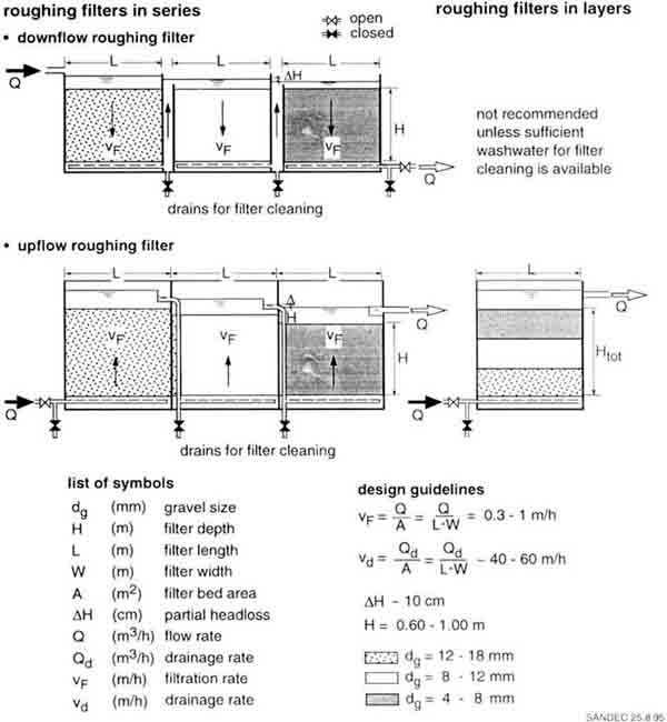
Fig. 38 Layout and Design of
Vertical-flow Roughing Filters
Vertical-flow roughing filters are usually operated at 0.3 to
1.0 m/h filtration rates. Vertical-flow roughing filters may be sensitive to
hydraulic fluctuations, especially if loaded with large amounts of solids.
Settled matter might be resuspended at increased filtration rates, causing
solids to break through the filter. Filter operation at constant flow rates is,
therefore, recommended. Raw water containing colloidal matter and a high
suspension stability should be treated at low filtration rates and preferably
with fine filter material. Filter resistance is usually less than 20 cm per
filter unit and, hence, not a decisive operational criteria for properly
designed and operated roughing filters.
Due to structural constraints, vertical-flow roughing filters
have a relatively small filter depth of about 1 m. Total filter depth of the
three filter units used in series is thus 3 m. This total available filter
dentin limits vertical-flow roughig filter application. It can generally and
efficiently handle moderate raw water turbidities of 50 to 150 NTU. Raw water
pretreatment by intake filters, reduction of filtration rate or provision of
additional filter boxes would be required to treat raw water of higher
turbidities.
In vertical roughing filters in layers, where all three
gravel fractions are installed in one filter box with a total filter distance of
about 1 m, low turbidity raw water can be pretreated. However, due to
cleaning aspects this filter design can only be used for upflow operated
roughing filters. In such filters, the coarse filter material is placed at the
bottom and the finest material at the top of the filter. The separated solids,
which accumulate mainly in the coarse filter fraction next to the filter bottom,
can be easily flushed out with the water stored in the filter. Therefore, the
use of upflow roughing filters in layers is recommended. Down flow roughing
filters in layers face considerable problems with hydraulic filter cleaning. The
bulk of solids accumulated in the coarse filter material on top of such filters
would have to be flushed through the finer rather clean filter material and
would thus soil the entire filter bed.
Adequate and efficient washwater collection is important
for reliable roughing filter operation. Perforated pipes or a false filter
bottom can be installed in vertical-flow roughing filters. Perforated pipes,
which should be laid in a coarse gravel pack to support an even washwater
abstraction, would require the installation of additional filter material in
vertical-flow roughing filters. Preference is given to false filter bottoms
as they allow an even washwater abstraction and do not require additional
gravel layers. Although special perforated concrete slabs will be necessary,
they may be readily produced locally.
A comparison of downflow with upflow roughing filters
reveals the following:
· Direction of flow and
sedimentation are obviously the first differences which might interfere or
support solids settling on the filter material. Solid removal efficiency should
consequently vary in the two filter types. Theoretically, downflow filters
should have a better performance than upflow filters as the solid particles are
more likely to settle on top of the gravel surface in the direction of flow than
under countercurrent conditions. However, practical field experience has shown
a similar efficiency for both filters. In dead filter zones, where the
water flow is reduced to a minimum, solids settle regardless whether the
roughing filter is operated in upflow or downflow direction. Hence, filter
efficiency is similar in both filter types.
· The accumulation pattern of
retained solids is another difference between downflow and upflow filters.
The bulk of the solids is deposited at the inlet of the filter; i.e., for
downflow filters in the upper part of the filter, and for upflow filters in the
filter medium located next to the filter bottom. This, however, has a
tremendous impact on hydraulic filter cleaning. In downflow roughing
filters, the buIk of accumulated solids has to be flushed with a relatively
small washwater volume from the soiled filter top through the lower and cleaner
filter part to the filter bottom. The opposite is true for upflow roughing
filters. The bulk of retained solids is accumulated next to the drainage system
and a relatively large washwater volume, accommodated in the upper filter part,
is available to flush the solids out of the filter. Owing to the important
filter cleaning aspect, use of upflow roughing filters rather than downflow
filters is recommended.
|
The Bathtub by the Riverside
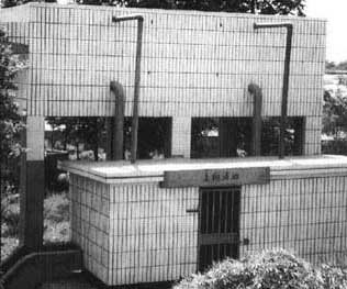
The Bathtub by the
Riverside
Xiaojiang township, located by the Qiantang river, the
largest stream in the province, faced tremendous problems with its water supply
scheme. The raw water was pumped over a distance of about 1 km from the river to
the treatment plant situated to the water tower in the centre of the town. In
1986, a public water supply was constructed using the "traditional" water
treatment technology, e.g. coagulants and bleaching powder were added to the raw
water, which was then pumped into a sedimentation tank and thereafter filtered
through rapid sand filters However, the river is known to carry large silt loads
especially during the rainy season. These solids, accumulated in the raw water
main, increased the headloss in the pipe and seriously reduced its hydraulic
capacity. Moreover, the water consumers drinking a lot of tea were always
complaining about the unpleasant taste of the distributed water.
Rehabilitation of the water treatment became inevitable
after six years of operation. Embarrassed by the situation, Mr Xu and his team
transformed the sedimentation tank into two upflow roughing filter units, and
constructed two new slow sand filters. All these installations were built behind
the surrounding wall of the existing treatment plant and did not attract much
public attention. However, these modifications did not solve the clogging
problem in the raw water pipe, and the small raw water pumping house could not
accommodate any installation larger than the common chemical dosing equipment.
The project team admitted their design errors and decided to expose themselves
to public criticism by erecting a gaudy and flashy structure.
To avoid a second pumping step, two additional upflow
roughing filters were constructed on an elevated positron next to the dam of the
river. The walls were covered with nice white tiles as commonly used in
bathrooms. However, Mr Xu and his team convinced by the efficiency of roughing
and slow sand filters had, on this occasion, made the right decision. Raw water
turbidity of 500 NTU is now reduced to 60 -180 NTU by the upflow roughing
filters, to 12 - 30 NTU by the second prefilters, and the filtrate of the slow
sand filters is now always less than 5 NTU. Even more important, the complaints
of the consumers have ceased since chemicals are no longer used to treat the
water, and the public has no reason to criticise the bathtub by the
riverside. |
10.4 Horizontal-flow roughing filters
Unlimited filter length and simple layout are the main
advantages of horizontal-flow roughing filters. Generally, the shallow
structure does not create structural problems, and the filter length is not
limited to a few metres. Furthermore, its simple layout does not require
additional hydraulic structures and installations as in vertical-flow roughing
filters. The raw water runs in horizontal direction from the inlet compartment,
through a series of differently graded filter material separated by perforated
walls, to the filter outlet as illustrated in Fig. 39. Filter material also
ranges between 20 and 4 mm in size, and is usually distributed as coarse, medium
and fine fraction in three subsequent filter compartments. To prevent algal
growth in the filter, the water level is kept below the surface of the filter
material by a weir or an effluent pipe placed at the filter outlet.
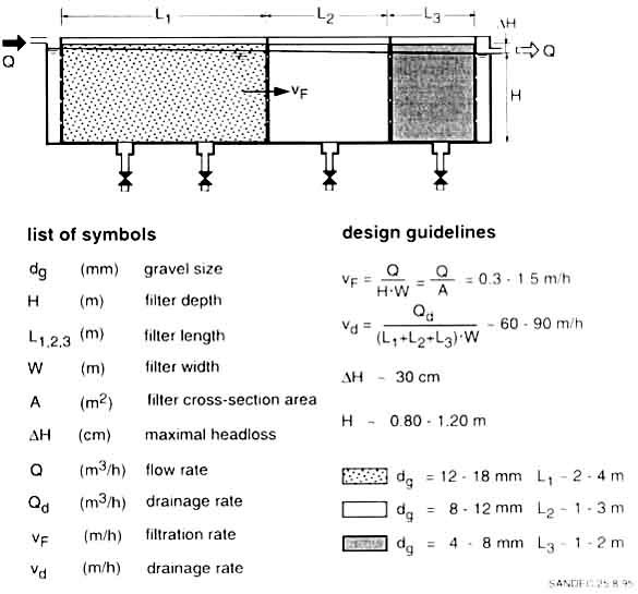
Fig. 39 Layout and Design of a
Horizontal-flow Roughing
Filtration rate in horizontal-flow roughing filters ranges
between 0.3 and 1.5 m/h. It has been defined here as hydraulic load
(m³/h) per unit of vertical cross section area (m²) of the filter.
Filter length is dependent on raw water turbidity and usually lies within 5 to 7
m. Due to the comparatively long filter length, horizontal-flow roughing
filters can handle short turbidity peaks of 500 to 1,000 NTU.
Drainage facilities, such as perforated pipes, troughs or
culverts, allow hydraulic filter bed cleaning. These drainage systems are
placed at the filter bottom perpendicular to the direction of flow. Drainage
facilities in flow direction must be avoided as they could create short-circuits
during normal filter operation. Hence, false filter bottom systems cannot be
installed in horizontal-flow roughing filters. Since most of the solids
accumulate at the inlet of each filter medium, drainage facilities should be
placed at the inlet of each filter compartment to enhance hydraulic cleaning
efficiency. Installation of troughs complicates construction of the filter box
floor. Furthermore, since the horizontal distance Ld between the
troughs is usually large, an even abstraction of the sludge is correspondingly
difficult. Therefore, use of perforated pipes is the best drainage system for
horizontal-flow roughing filters, as it allows easy installation of a
dispersed system. Although prefabricated culverts may allow a more even solids
removal, connection to the washwater effluent pipes is more complicated.
Horizontal-flow roughing filters have a large silt storage
capacity. Solids settle on top of the filter medium surface and grow to
small heaps of loose aggregates with progressive filtration time. Part of the
small heaps will drift towards the filter bottom as soon as they become
unstable. This drift regenerates filter efficiency at the top, and slowly silts
the filter from bottom to top. Horizontal-flow roughing filters also react less
sensitively to filtration rate changes, as clusters of resuspended solids will
drift towards the filter bottom or be retained by the subsequent filter layers.
Horizontal-flow roughing filters are thus less susceptible than vertical-flow
filters to solid breakthroughs caused by flow rate changes. However, they may
react more sensitively to short circuits induced by a variable raw wafer
temperature.
Periodic cleaning is also essential for horizontal-flow
roughing filters. Hydraulic cleaning is carried out by fast drainage of the
water stored in the filter. During filter drainage, the small unstable heaps of
accumulated solids collapse and are flushed towards the filter bottom. The solid
matter stored in the filter material is washed out of the filter box through the
drainage system. Drainage velocities of 60 to 90 m/h are necessary to
achieve a good hydraulic cleaning efficiency. Drainage pipes of adequate size
are required to achieve the recommended velocity which drains the filter within
1 to 2 minutes. Depending on the solids concentration in the raw water, regular
hydraulic filter cleaning, at intervals of every few weeks, is required to avoid
deterioration of filter efficiency and development of excessive filter
resistance. However, filter resistance will not exceed 20 cm if normal filter
operation and regular cleaning are observed. Frequent and efficient filter
drainages will also defer the need for manual filter cleaning, which nonetheless
becomes unavoidable after some years of filter operation.

Photo 6 Inside View of a Roughing
Filter Bed during Hydraulic Cleaning
|
Learning from Developing Countries

Learning from Developing
Countries
Water demand of Basle's agglomeration has been increasing
gradually due to industrialisation and migration into the prospering area. Newly
constructed buildings and highways have contributed to surface sealing and have
reduced natural groundwater recharge. Increased water demand and reduced
recharging rate have led to an alarming drop in the groundwater table. The
groundwater wells almost ran dry. In order to reverse this situation, an
artificial groundwater recharge plant was constructed in Aesch in the early
1970s.
Raw water was pumped from the river Birs into a lagoon for
coarse matter separation from where it was conveyed to horizontal-flow roughing
filters for fine solids separation. It was then aerated by cascades before
flowing into the large lagoon which acts as slow sand filter. The treated water
was finally led to recharge wells through the impervious top layer into the
aquifer. Although the original capacity of the plant was designed for 400 l/s,
operation had to be reduced to 200 l/s due to operational problems. Inadequate
solids removal efficiency and gradual silting of the recharge wells were the
reasons for the reduced treatment plant operation and for the repeated drop in
the groundwater table.
The horizontal-flow roughing filters were designed
according to the layout illustrated in Fig. 22. The 15-m long roughing filters,
filled with one gravel fraction amounting to 50 - 80 mm in size, were operated
at 5-10 m/h filtration rates. This inappropriate design and operation resulted
in poor solids removal efficiencies. The slow sand filter was rapidly clogged so
that the partly treated water ran through the coarse material of the embankment
directly into the recharge well. Furthermore, since the roughing filters could
not be cleaned hydraulically, the gravel had to be replaced every six years - a
costly undertaking which caused headaches to the management of the water
authority.
In the last decade, the roughing filter technology has,
however, been developed to a viable treatment alternative in the developing
countries. The responsible water authority had access to the necessary
information and field-tested the new roughing filters. The comparative test
results revealed important improvements; i.e., the small upflow roughing filters
with a total filter length of 1 m had up to a six times higher solids removal
efficiencies than the old filters. Since they could also be cleaned
hydraulically operating costs were reduced The high-tech society was amazed by
the efficiency of this low-cost technology. |
11. Roughing filter efficiency
11.1 Practical experience
Treatment efficiency is dependent on raw water
characteristics, layout and operation of roughing filters. On the one hand,
size, concentration, type of particles and suspension stability are the most
important water quality parameters influencing suspended solids removal
efficiency. On the other hand, filter material size and filter length, applied
filtration rate and cleaning frequency are the key factors determining filter
efficiency. Hence, roughing filters with identical layout and operation may vary
in filter performance with different raw water sources. Even a specific filter
will most probably not have a constant filter efficiency with the same raw water
source: high particle removal rates will be recorded during periods of high raw
water turbidity where a slower rates will be experienced during periods of
moderate raw water turbidity. Therefore, an exact indication of filter
efficiencies is generally quite impossible.
Treatment efficiencies of different roughing filters have
been studied extensively by CINARA [47] at a pilot plant in Puerto Mallarino,
Cali, Colombia (reported also in [48]). These field tests are considered the
most comprehensive pilot plant studies for roughing filter development. The
pilot plant consists of a first pretreatment step using intake/dynamic filters
to precondition the raw water drawn from the Cauca River. The flow is then split
into five lines where the filter performance of different roughing filters is
tested in combination with identical slow sand filters used as reference. The
following types of roughing filters are installed at Puerto Mallarino:
|
upflow roughing filter in series |
URFS |
|
upflow roughing filter in layers |
URFL |
|
modified horizontal-flow |
|
|
roughing filter |
MHRF |
|
horizontal-flow roughing filter |
HRF |
|
downflow roughing filter in series |
DRFS |
All roughing filters have similar gravel fractions but differ in
filter length. Total filter length of URFS, MHRF and DRFS, amounts to 4.40 m.
Total filter length of the HRF unitis 7.10 m and 1.60 m for the URFL unit. The
slow sand filter units are circular in shape, 2.00 m in diameter and 2.00 m in
height. They were filled with a 1 -m deep sand layer, which was gradually
reduced due to subsequent sand cleanings, but never fell below 0.60 m. The sand
has an effective diameter of 0.2 mm and a uniformity coefficient of 1.57.
Fig. 40 summarises filter efficiencies of the different
roughing filters with respect to turbidity removal at different filtration
rates and two distinct raw water turbidity levels. The graphs show higher
removal rates of generally 85 - 90% or more for periods of high turbidity (150 -
500 NTU). Filter efficiency is reduced to about 80 85% or less during periods of
moderate turbidity (30 - 50 NTU), and is hence in accordance with the general
filter theory. The different but small filtration rates had no significant
influence on the turbidity removal efficiencies of the filters, as laminar flow
prevailed in all gravel fractions also at the highest filter velocity of 0.60
m/h, The upflow roughing filter in series and the horizontal-flow roughing
filter unit exhibited best performance throughout all test conditions. The
smallest turbidity removal efficiency was achieved by the downflow roughing
filter unit.
Fig. 41 elucidates the efficiency of the different pilot
plant treatment steps with respect to suspended solids and faecal conform
reduction. The intake/dynamic roughing filters reduced the average suspended
solids concentration by 55% from about 200 mg/l to 90 mg/l. This concentration
was further reduced to less than 5 mg/l by the roughing filters and the filtrate
of the slow sand filters had an average suspended solids concentration of 0.2 -
0.3 mg/l. The relatively high suspended solids concentration of the upflow
roughing filter in layer might be an indication of a comparatively low process
stability of this filter.
Average faecal coliform concentration of the raw water of about
40,000 CFU/100 ml was subsequently reduced to about 24,000, 400 and to less than
1 CFU/100 ml by the treatment scheme consisting of intake/dynamic filters,
roughing filters and slow sand filters. The modified horizontal-flow roughing
filter had the smallest faecal coliform removal efficiency of 96.5%. This rate
also influenced performance of the subsequent slow sand filter, which produced
an average effluent of 2.6 CFU/100 ml. All the other slow sand filters had
average faecal coliform concentrations of less than 1 CFU/100 ml in their
effluents.
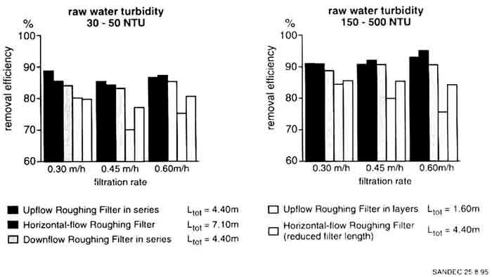
Fig. 40 Turbidity Removal by
Different roughing filters
Fig. 41 documents the high treatment efficiency of the pilot
plant. The two pretreatment steps and the slow sand filters were able to
reduce the suspended solids concentration from about 200 mg/l to about 0.2 mg/l,
or by 3 log, whereas the faecal coliform concentration was reduced from about
40,000 CFU/100 ml to generally less than 1 CFU/100 ml, which corresponds to a 4
- 5 log reduction.
Full-scale treatment plants are not so extensively monitored and
controlled as pilot plants. Nevertheless, Fig. 42 documents the development
of biological filter activities in the filters of a community water supply [52].
The raw water of La Javeriana's treatment plant originates from the Pance
River, a highland river of moderate turbidity. The water is treated by an intake
filter, two horizontal-flow roughing filters, and two slow sand filters operated
at 1.3, 0.6 and 0.08 m/h filtration rates. Faecal coliform concentration ranging
between about 1,000 and 10,000 CFU/100 ml is proof of relatively high faecal
contamination of the raw water. Turbidity of about 20 NTU is relatively low
during the dry periods, but increases to short turbidity peaks after periods of
precipitation. The apparent colour averaging about 100 CU/I follows a similar
pattern as turbidity. Mean faecal coliform concentration in the pretreated water
amounted to about 200 CFU/100 ml and did not decline during the monitoring
period of half a year. Although the treated water had initially somewhat
elevated faecal coliform concentrations of more than 10 CFU/100 ml, the effluent
concentration levelled out to about 1 CFU/100 ml after three weeks of operation.
This corresponds to the period of maturation of the slow sand filter. The
overall turbidity and apparent colour reduction, however, indicated a distinct
improvement within the first six months of operation. With progressive filter
operation, the respective treatment efficiencies also increased in the roughing
filter, most probably on account of the gradual development of biological
processes in this filter.
Table 4 summarises treatment efficiencies of roughing filters
operated at different flow directions. The filter material in the downflow
and horizontal-flow roughing filter is rather coarse compared to the one used in
the upflow roughing filter operated, however, at more than double the normal
filter velocity. Nevertheless, in all three treatment plants, turbidity
reduction by the roughing filters amounts to about 70 - 90%. The bacteriological
water quality improvement was about of the same order for these three treatment
plants.
Treatment efficiency of roughing filters is also limited
as they are not capable of treating any type of water as illustrated by the
following example [56]. Construction of a water supply scheme was one component
of the Laka Laka multi-purpose project. The project team decided to draw raw
water from the newly constructed water irrigation reservoir to supply their
scheme. High raw water turbidity lead to extremely short filter runs of the two
slow sand filters. Two horizontal-flow roughing filters were therefore designed
on the basis of the available literature data in order to improve operation of
the slow sand filters. The 18-m long roughing filters were operated at 2.5 m/h
filtration rate. Since filter efficiency was very poor at this rate, filter
velocity was gradually reduced to 0.5 m/h, but without achieving a substantial
treatment efficiency improvement. These problems were encountered mainly because
roughing and slow sand filters have never been used in this area before.
However, they could have been avoided by pilot plant tests (which are strongly
recommended in such a situation) conducted during the project design phase.
|
Microbiological Benefits from Gravel Filters

Microbiological Benefits from
Gravel Filters
In 1977, a water supply was constructed in the community
of Cocharcas located in an agricultural area of the high Andean Sierra and
numbering about 1,000 villagers. Its typical design comprises an abstraction
from an irrigation canal, a sedimentation tank, two slow sand filters a
reservoir, and a distribution system with single-tap household connections. By
1985, the water supply scheme had seriously deteriorated. The system was only
working two to three hours a day owing to the frequent use of the irrigation
canal by other villagers. Neither the intake nor the treatment plant had a flow
control system. The caretaker was only concerned with filling up the reservoir
as quickly as possible. Thus, since the slow sand filters were heavily
overloaded and without treatment efficiency, faecally polluted water was
supplied to Cocharcas. Rehabilitation of the system was thus necessary and an
agreement on water use with the neighbouring communities was therefore concluded
A small weir installed at the intake site revealed the limited need for water of
the village as compared to that required by agriculture. To allow adequate
operation of the slow sand filters and as additional raw water pretreatment
step, two gravel filters were constructed with community participation. The
treatment plant is now running at a constant flow and the efforts were rewarded
by the following water quality improvement data: |
|
Faecal Coliforms |
mean |
% reduction |
% reduction |
|
(counts/100 ml) |
value |
per trmt step |
cumulative |
|
raw water |
20,000 |
- |
- |
|
sedimentation tank |
14,500 |
27 |
27 |
|
gravel filter |
1,200 |
92 |
94 |
|
slow sand filter. |
20 |
98 |
99,9 |
|
The Andean experience reveals that gravel prefilters
enhance slow sand filter. operation and increase the overall plant performance.
The multiple barrier system proves to bean appropriate concept for rural water
supply.
|

Fig. 41 Suspended Solids and Faecal
Coliform Reduction by Roughing and Slow Sand
Filtration
11.2 Pilot plant tests
As described in the previous chapter, the worldwide
experience with roughing and slow sand filters documents the significant
potential of this treatment concept in producing potable water from polluted
turbid surface water. There is no doubt about the general treatment efficiency
of slow sand filters, since a biologically mature filter will consistently
reduce the concentration of microorganisms by 2 to 4 log (99 to 99.99%
reduction). It is more a question of specific treatment efficiency of roughing
and slow sand filters when fed with a local raw water source. Hence,
treatability of a particular raw water is of major concern to design
engineers, especially if local practical experience with the considered
treatment process and raw water source is not available.
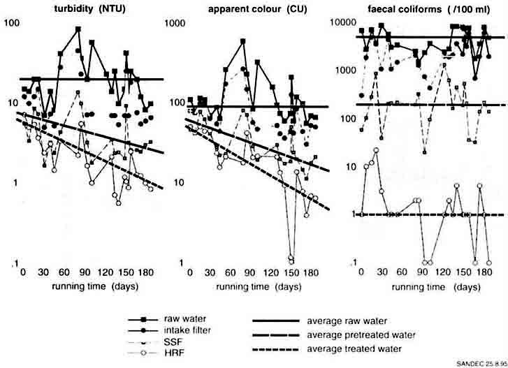
Fig. 42 Turbidity, Apparent Colour
and Faecal Coliform Reduction at the Treatment Plant La Javeriana, Colombia
Table 4 Examples and Practical Experience with Roughing
Filters
|
Layout and Performance |
Azpitia, Peru |
El Retiro, Colombia |
Blue Nile Health Project, Sudan |
|
type of roughing filter |
downflow |
upflow
(multi-layer filter) |
horizontal-flow |
|
filtration rate |
0.30 m/h |
0.74 m/h |
0.30 m/h |
|
design capacity |
35 m³/d |
790 m³/d |
5 m³/d |
|
filter length |
60 cm, F 40-25 |
20 cm, F 18 |
270 cm, F 25-50 |
|
and size (mm) |
60 cm, F 25-12 |
15 cm, F 12 |
85 cm, F 15-20 |
|
of material |
60 cm, F 12- 6 |
15 cm, F 6 |
85 cm, F 5-10 |
|
|
15 cm, F 3 |
|
|
turbidity (NTU) |
|
· raw water |
50 - 200 |
10 - 150 |
40 - 500 |
|
· prefiltered water |
15 - 40 |
5 - 15 |
5 - 50 |
|
faecal coliforms [/100 ml] |
|
· raw water |
700 |
16,000 |
> 300* |
|
· prefiltered water |
160 |
1.680 |
< 25* |
|
reference |
[53] |
[54] |
[55] |
* as E.coli
|
Limits of Roughing Filters

Limits of Roughing
Filters
The Laka-Laka Project in the Andean region is a
multi-purpose project aiming at providing water to a large irrigation scheme and
to Tarata, a small town of 3,000 inhabitants located next to the newly
constructed gravity dam. The water in the reservoir was brownish in colour and
had to be treated before it could be used as drinking water. A local
non-governmental organisation (NGO) experienced in community work but lacking
technical know-how in water supply was responsible for project implementation.
Water treatment design was based on some Literature gathered by the local
staff.
Two large slow sand filter. units were constructed in a
first phase, however, they were rapidly clogged by the turbid raw water. The
literature was again consulted and the staff decided to construct two
horizontal-flow roughing filters as recommended in the manual Each of these
filters had a total filter length of 18 m and were operated at a flow rate of
more than 2.5 m/in. However, turbidity could skill not be reduced significantly
by the prefilters. Since treatment plant construction had been carried out with
community participation, Tarata's citizens expected a good water quality after
their substantial contribution towards the treatment plant construction.
Relations between field staff and local population became tense.
As roughing filters had not been used in their country so
far, the NGO sought advice from water treatment experts of a neighbouring
country. Ana Mar�a was contracted as consultant to the project. During her first
field visit, she went to inspect the reservoir and saw the same brownish raw
water flowing out of the roughing filters operated at reduced flow rates as
recommended before she visited Tarata. The last rain had ended three months
prior to her visit, however, the raw water stored in the reservoir had hardly
changed appearance since then. Turbidity was still around 300 NTU. Ana Mar�a's
preliminary conclusion was confirmed by laboratory tests which revealed that the
raw water was carrying a large amount of colloidal matter which could not settle
in this stable suspension.
Field tests had to be conducted to determine the most
adequate treatment scheme for this cliff cult raw water. The local NGO set up a
small pilot plant according to the design of the consultant. It was located next
to the inlet of the old gravel filters consisting in three concrete rings used
as upflow roughing filters and a larger ring simulating the slow sand filter.
The three columns were filled with gravel from the old filter, however, alum
sulphate and lime were added to the effluent of the first column. Hence, the
second two units were operated as contact filters and their efficiency was
extraordinary. The raw water turbidity of about 350 - 400 NTU was reduced to
about 340 NTU in the first filter column, to about 20 NTU in the second, and to
1.5 NTU in the third filter column at a dosage of 40 mg/l alum sulphate and a pH
of 10 adjusted with the addition of lime. The pilot plant results were used as
design values for the rehabilitation of the treatment plant.
This experience proves that each treatment process has its
limitation just as the competence of field staff. |
A wide range of raw water qualities can theoretically be treated
by conventional water treatment processes; i.e., coagulation, flocculation,
sedimentation, rapid sand filtration and chlorination, as these treatment
schemes are flexible with regard to chemical dosage, detention time, hydraulic
loads, and water pressure. In contrast to such schemes, roughing and slow sand
filters are rather limited in operational flexibility but provide high process
stability. Owing to the simplicity of the roughing and slow sand filter
technology, only the following three salient points will have to be answered by
pilot plant studies:
· can roughing filters reduce
raw water turbidity to a level required for reasonable slow sand filter
operation?
· at what rate does the
headloss in the slow sand filter increase?
· on what design values
should the project layout be based?
The first question centres on pretreatment efficiency of
roughing filters with regard to turbidity reduction. A comprehensive
literature review [17] reveals that an upper turbidity limit amounting between 5
and 20 NTU will allow a reasonable slow sand filter operation. The most adequate
pretreatment scheme is dependent on the raw water characteristic. However,
information on raw water quality is quite often scarce or not available,
especially for small surface water sources. The lack of water quality data
can be partly offset by a characterisation of the raw water source. A highland
river, lowland stream or a still surface water will carry different types of
solid matter. An inspection of the water course and the study of sludge deposits
in the river bed and on the embankment will provide information on type and size
of solids found in the water during periods of high discharge. Interviews with
the local population might provide some details on seasonal water level
fluctuation and type of turbidity (colour, period of turbidity peaks) over the
year. Finally, simple tests, such as settleability and suspension stability
tests as described in Annex 1, will generate valuable information on the
separation characteristics of the solids. The information obtained will help to
select the type and number of pretreatment steps as presented in Chapter 12.
Efficiency of the chosen pretreatment scheme will then be assessed in a small
pilot plant as outlined in Annex 5.
The second question focuses on the development of headloss in
the slow sand filter. The rate of filter resistance increase is crucial for
the determination of slow sand filter performance in treating a specific
pretreated raw water. Slow sand filter runs (time between two consecutive filter
cleanings) of at least one month should be possible. Frequent filter cleaning
would interfere with the biological activities concentrated mainly on the filter
bed; i.e., in the so-called "Schmutzdecke". Slow sand filters with short filter
runs of a few days act predominantly as physical filters and are thus not able
to substantially improve the microbiological water quality. Development of the
"Schmutzdecke" is known as ripening period and greatly depends on the organic
load and biological raw water composition. This biological layer gradually grows
on top of the sand bed and becomes more compact with progressive filtration
time. Thus, the water level will start to increase in an inlet controlled slow
sand filter. The filter has to be cleaned the moment the supernatant water level
reaches the overflow. Since every water is unique with respect to the building
up of the "Schmutzdecke", development of the headloss should be recorded by
simple piezometer readings. Operational characteristics of slow sand filters
should therefore be studied by pilot plant tests if practical experience is
not available locally.
The last question aims to optimise treatment plant design.
Size and filter layout may be modified once the selected treatment scheme
has proven its general suitability. The hydraulic filter load has a direct
impact on the size of the structures as it influences them proportionally.
However, roughing and slow sand filters should not be designed on the basis
of their highest permissible filtration rate. Use of more conservative
values is recommended, e.g. a filtration rate of 0.1 0.2 m/h for slow sand
filters. Higher filtration rates may anyhow be necessary with increasing water
demands. However, installation of a prefilter as a first pretreatment step, use
of finer filter material in the roughing filters or reduction of the depth of
the sand could offer cost saving alternatives which can be assessed by pilot
plant studies.
Additional aspects are, however, necessary in the
planning and implementation phase of pilot plant studies. These will include:
- location of the raw water intake should, whenever
possible, be identical with that of the planned treatment plant. However, the
raw water supply might create some problems, especially if the water has to be
pumped. In this case, tapping of raw water from another water supply system
using the same raw water source should be investigated. A continuous raw water
supply is essential for adequate pilot tests. Provision of a raw water tank is
necessary if water cannot be pumped or supplied continuously.
- access to the pilot plant should be easy and possible
throughout the year. The site should be protected from vandalism and robbery and
allow easy discharge of filter drainage water. Availability of a small storage
room for field test equipment near the pilot plant would be advantageous.
- the material required for the pilot plant should be
available locally. PVC or concrete pipes with a minimum diameter of 30 cm can be
used to simulate vertical flow roughing or slow sand filters. Slow sand filters
can also be installed in ferro-cement tanks. Horizontal-flow roughing filters
however require the construction of open channels to allow adequate filling of
the filter material. Recommendations and design examples of pilot plant layouts
are illustrated in Annex 5.
- the pilot plant tests should last for several months.
The field test period should at least cover the period with the highest raw
water turbidity and ideally run over a full year. To gain preliminary
operational experience with the pilot plant, field tests should start a few
months prior to the expected turbidity peaks.
- pilot plant operation must be performed at constant
flow conditions. Generation of conclusive test results requires unchanged
operational conditions throughout a complete filter run. Since slow sand filter
test runs might last more than a few months, operation of filter units in
parallel are recommended for the study of different design options.
- the pilot plant should be monitored by local people
trained on the job. A daily visit should entail the control of the flow through
the filters, measurement of the raw water turbidity and that of the different
treatment steps, as well as recording of the headloss development in the slow
sand filter. Additional water quality analyses with field test kits or in the
local laboratory are included in the monitoring programme. A monitoring
programme is outlined in Annex 5.
- the field test report presents the results of the
monitoring programme, evaluates the data and draws conclusions for the design of
the full-scale treatment plant. The large number of data are best reported in
tables and in the form of graphs. Water quality data are usually graphically
illustrated on a normal or logarithmic scale as a function of filtration time
plotted on a normal scale.
Field tests with pilot plants not only cover technical
issues, they also have the following important side effects:
- presentation of the treatment process to the future
beneficiaries. Laymen may have little knowledge about the technical aspects
of a treatment plant, but may still have to construct their own treatment plant
through a self-help project. Motivation of community work could prove very
difficult if the villagers have no idea of the kind of structures they are
supposed to build. A pilot plant is best suited to introduce the prospective
water treatment facility to the general public.
- demonstration of the treatment efficiency to the future
consumers. Villagers are far more motivated to contribute by cash and kind
to the proposed treatment plant if they can see for themselves how the water
quality changes. They should also taste the treated water and look at its
appearance. Bacteriological water quality improvements could be demonstrated to
the public with colony counts on membrane filters for raw and treated water.
Appreciation and acceptance of the treated water quality by the consumers are
important criteria for long-term use of a treatment plant.
- training of future treatment plant personnel.
Involvement of local staff in the construction, operation and monitoring of
a pilot plant is an excellent training opportunity for future treatment plant
operators. Experience with pilot filter operation is directly transferable to
full-scale operation.
It can therefore be concluded that pilot plant tests should
be conducted with roughing and slow sand filters in areas where practical
experience is not yet available. Field tests are recommended particularly with
raw water exhibiting a high suspension stability. Pilot plant tests should also
be conducted prior to the design of large-scale treatment plants to achieve a
more cost-effective layout. Finally, field tests will determine raw water
treatability and avoid failures with respect to roughing and slow sand filter
application.

Photo 7 Vertical Roughing Filter
Column
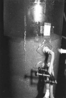
Photo 8 Slow Sand Filter Column
|
Unexpected Iron Mine in Roughing Filters

Unexpected Iron Mine in
Roughing Filters
The town of Damongo in West Africa, which numbered 12,000
inhabitants, had a piped water supply system with a daily water capacity of 180
m³ . This capacity was limited by the package water treatment plant which
had to be replaced due to serious corrosion and unavailability of spares. The
regional water authority therefore started to study alternatives for the package
plant. As practical experience with roughing and slow sand filters was now
available in the region, such a treatment Option had to be field-tested.
Daniel and Charles, two enthusiastic junior engineers were
in charge of pilot plant design. Two 5m long horizontal-flow roughing filter
units were constructed and filled with gravel from a nearby quarry identified as
potential filter material source for the planned 1000 m³/d treatment plant
capacity.
Field tests started soon after completion of the pilot
plant. Turbidity reduction by the roughing filters was noticeable but not
sufficient. Turbidity removal of the slow sand filter. was good and its effluent
generally amounted to less than 5 NTU. However, the prefiltered water increased
in turbidity and the colour of the wafer did not charge. Therefore, a laboratory
chemist was called to the site to take water samples for quality
analysis.
The chemical analysts did not disclose spectacularly new
facts apart from a total iron content of 0.05 - 0.1 mg/l in the raw water and
0.2 - 0.6 mg/l in the filtrate of the gravel filters Daniel and Charles blamed
the chemist for his inaccurate work and accused him of having mixed the samples.
The analysis was repeated but produced similar results. Perplexed by the
situation, the young engineers started to investigate the filters. How can a
filter increase the iron concentration ? The red surface of the gravel led them
to the solution; i.e., the water flowing through the filter dissolved iron from
the lateritic material.
The roughing filters performed well after the gravel had
been exchanged by filter media found elsewhere. However, the experience with the
"hidden iron mine" saved the project from additional costs, as replacement of
filter material in the 1000 m³/d would have been quite an expensive
undertaking. |
12. Selection criteria for roughing filters
Roughing filters are primarily used to separate fine solids
from the water that are only partly or not retained at all by stilling
basins or sedimentation tanks. Roughing filters mainly act as physical filters
and reduce the solid mass. However, the large filter surface area available for
sedimentation and the relatively small filtration rates also support adsorption
as well as chemical and biological processes. Therefore, besides solid matter
separation, roughing filters also partly improve the bacteriological water
quality and, to a minor extent, change some other water quality parameters,
such as colour or amount of dissolved organic matter.
Since several different prefilter types are available,
such as intake and dynamic filters, downflow and upflow roughing filters,
and finally horizontal-flow roughing filters, choice of the most appropriate
pretreatment method becomes difficult. Selection of an adequate treatment
scheme should be based on the following criteria:
· raw water
characteristics
· type of surface
water
· topography at the intake and at the
treatment plant site
· economic
aspects
· operational aspects
The first two aspects focus mainly on raw water quality and are
discussed in the next chapter. The last three criteria deal mainly with
treatment plant layout and operation, and are therefore considered in a second
separate
chapter.
12.1 Raw water quality as selection criteria
The raw water characteristics determine to a large extent
the type of pretreatment process. Turbidity and suspended solids fluctuation is
thus the most important information required for the selection of the
pretreatment scheme.
· Average and maximum levels
of turbidity and suspended solids concentration are of great importance for
the design of pretreatment units. In addition, information on the period of
turbidity and suspended solids concentration peaks is essential. Do such peaks
last for a few hours, some days or a few months? Furthermore, the solids should
also be characterised according to their settleability and size. Do particles
settle easily in the water or remain suspended? Finally, some information on the
organic matter content would be useful.
· Information, especially on
peak values of solids concentration, is unfortunately often missing. The
sanitary engineer is thus forced to assess peak values or, in case of an
available database, he will use the probability paper analysis before designing
a treatment scheme. Some simple sedimentation tests carried out during periods
of high and normal river discharge will allow the study of the settling
properties of the solid matter and characterisation of the suspension stability.
Separation of coarse sand and silt can certainly be achieved by a grit chamber,
while finer settleable matter can be removed by sedimentation tanks. Roughing
filters will separate suspended solids, but may only partly remove colloidal
matter.
· The faecal pollution level
should also be taken into account when designing pretreatment units as they
can improve, to some extent, the microbiological quality of the raw water.
Hence, they act as first hygienic barriers and reduce the load of pathogenic
microorganisms on the slow sand filters. The faecal pollution level in a raw
water source can be assessed by bacteriological analysis; i.e.,
determination of faecal conform concentration. This type of analysis requires
special equipment and expertise. Furthermore, a random water test is only
representative of the water quality at the time of sampling. Several samples
have to be taken at different times, especially in flowing surface water, to
characterise the faecal pollution level in surface water. A sanitary survey
of the catchment area may roughly assess the possible magnitude of faecal
water contamination. This requires inspection of the water course and its
contributors, investigation of wastewater and faecal disposal practices,
assessment of dilution during minimum flow, as well as study of human activities
in the catchment area. The adapted Table 5 proposed in [6] presents a rough
surface water classification system with respect to hygienic risk. It may be
used as preliminary determination of the faecal pollution level in surface
water.
Table 5 Speculative Surface Water Classification with Respect
to Health Risk
|
health risk by consumption of untreated water |
E.coli/faecal coliform [count/100 ml] |
possible situation for surface water |
|
no risk |
0 |
draining a well-protected catchment area |
|
low |
1 - 10 |
extensive farming in catchment area |
|
intermediate |
10 - 100 |
farming and scattered houses in catchment area |
|
high |
100 - 1000 |
small settlements and water use upstream of intake |
|
very high risk |
> 1000 |
large settlements with wastewater discharge upstream of intake
|
In brief, average and maximum turbidity levels and suspended
solids concentration, solids settling properties, as well as peak concentration
period, are the most important raw water characteristics for selection and
design of pretreatment units. Faecal pollution level must be taken into
consideration when designing entire treatment schemes.
Surface water type has also a strong impact on the
characteristics and amount of solids carried by the water. Small upland rivers,
large lowland streams and still surface water generally differ from each other
as shown in Fig. 17 and described hereafter.
· Small upland rivers
draining a catchment area, protected by a manifold and rich vegetation, will
probably have a clear or tinted water colour during periods of mean discharge.
Coloured water can be observed especially in slow flowing waters in contact with
organic matter, such as in rivers flowing through dense forests or swampy areas
where water washes out humic substances from decaying material and turns
yellowish or brownish. The colour, which may be partly reduced by roughing
filters due to biological activities, will not affect slow sand filter operation
which will further reduce colour. The small upland rivers will react to heavy
but short periods of rainfall with a sudden increase in run-off and water
quality change. Turbidity peaks and/or increase in colour are usually
correlated with river discharge. These peaks decrease with falling water
level as soon as precipitation stops. In such cases, either intake or dynamic
filters may be used to reduce the extreme peak values or to protect the
treatment plant from heavy solid loads discharged by the river for a few hours.
· Large lowland streams
have a different regime. Local showers do not greatly affect their discharge
or water quality. Annual rainfall distribution, including the wet and the dry
seasons, have a greater influence on the discharge. Changes occur gradually
over a period of some days or weeks when increased turbidity levels or suspended
solids concentration are recorded for a few weeks or months. Water quality
fluctuations, expressed as ratio between average and maximum values, are usually
smaller than in upland rivers. Therefore, pretreatment is permanently required
and use of roughing filters, possibly combined with intake filters, is
recommended. The choice of roughing filters is dependent, among other aspects,
on the level and period of high turbidity or suspended solids concentration. As
a rule, moderate turbidities can be treated with vertical-flow roughing filters
in series and higher raw water turbidities possibly with horizontal-flow
filters.
· Still surface water
will probably exhibit the smallest water quality changes. The influent of
reservoirs, ponds and lakes undergoes natural treatment processes. Suspended
matter will settle and microorganisms will die off with increasing retention
time. Nevertheless, suspended and colloidal matter may still remain suspended
and algae may grow depending on the degree of eutrophication and extent of
solar radiation. To protect the subsequent slow sand filter units from excessive
fine solids and algal loads, use of finely graded roughing filters may be
appropriate and necessary in such situations.
In short, small upland rivers draining erosion-protected
catchment areas are likely to be of low turbidity which may, however, increase
to peaks of short duration during periods of heavy rainfall. Such conditions
favour the use of dynamic and intake filters. Large lowland streams are
generally more turbid and change their quality only gradually and according to
the annual seasonal pattern. Use of roughing filters, possibly combined with
intake filters, may offer an appropriate option for the pretreatment of lowland
river water. Suspended solids, colloidal matter, and algae of a stagnant water
source, require as pretreatment method the application of finer graded roughing
filters.
Fig. 43 offers a matrix for the selection of an adequate
surface water treatment scheme. Type and concentration of solid matter, as
well as level of faecal pollution, are the decisive criteria for the
determination of the most appropriate separation process. Surface water greatly
differs with respect to these quality parameters. However, information on these
characteristics and values for a specific raw water source is generally rather
basic. Hence, this matrix provides engineers with some guidelines for designing
water treatment schemes.
The design of roughing and slow sand filters is usually
conservative, i.e., it allows uncertainties with respect to raw water quality
and treatability. However, additional tests will allow a more accurate
design of the treatment units. Settleability and suspension stability tests,
characterisation of solids according to type and size (inorganic matter such as
silt or clay particles; organic material such as plankton or algae) and their
concentration in the raw water will assist in selecting the appropriate
filtration rate, gravel size and filter length. In addition, raw water may
contain other pollutants, such as true colour, dissolved organic matter, iron or
manganese which need to be separated or reduced. Field tests are usually
necessary to determine the removal rate of these substances by roughing and slow
sand
filtration.
12.2 Layout and operational aspects as selection criteria
The topography has to be taken into consideration in the
design of water supply schemes. Location of the intake, topographical conditions
of the site and operational aspects are essential criteria for the conceptional
layout of water supply systems.
· Surface water intakes
often have to be located in remote places to allow the strongly recommended
construction of gravity schemes. However, access to the remote intake sites is
often difficult, usually time-consuming and regular control and cleaning of the
installations not guaranteed and quite often neglected. In such a case,
pretreatment at the intake should be reduced to coarse solid removal, and the
actual water treatment should only be carried out at the treatment plant,
generally located in front of the reservoir and as close to the supply area as
possible.
· Local topography may
favour construction of a small canal for controlled diversion of surface water
and, consequently, installation of an intake or dynamic filter. Favourable river
bed conditions may also allow construction of infiltration galleries.
· Drainage aspects should
be considered carefully. Intake filters usually operate with drained excess raw
water. Hence, their use in a pumped raw water supply system according to
standard design (see Fig. 37) is generally not the best option. Intake filters
without raw water discharge should be used instead. Furthermore, operation of
roughing filters requires an adequate topography for washwater disposal. High
wastewater discharges must be possible without causing erosion. The
installations should be large enough for runoff to discharge into a receiving
water course or, preferably, into a pond especially constructed for washwater
storage.
Summing up we can say that gravity schemes should be
constructed whenever possible, although they may often require remote intakes
which are difficult to maintain. Nevertheless, favourable topographical
conditions should be used for the installation of intake and dynamic filters to
reduce wastewater discharge problems at the treatment plant site; an aspect
requiring careful consideration with roughing filters.

Fig. 43 Algorithm for the Design of
Surface water Treatment Schemes Using Roughing and Slow Sand Filtration
|
Cheap Gravel
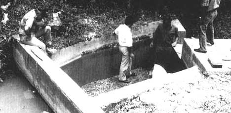
Cheap Gravel
Fontanero Tulio, caretaker of Taminango's water supply
scheme, located in a south-western region of the Andean range, led our small
expedition towards the water intake structure. Along the steep path winding
through dry barely cultivated or used grassland, we passed a few rundown
haciendas providing shade to some cattle. Although it was already late
afternoon, the sun was still strong A splendid view of the hilly highland spread
peacefully below us and rewarded our tedious 2-hour walk. The narrow trail
flattened after the vantage point and led into a narrow valley covered by small
trees and bushes, an indication for the presence of water. After regaining our
breath on the flat stretch I enquired when the local people had last visited the
intake. "About two weeks ago" was Tulio's answer, whereas the District Engineer
declared to have inspected the site a month after the intake had been
reconstructed within the frame of a field study project. Gentle splashing
announced the nearby water source and, after a final jump through small bushes,
we reached the brooklet. Rehabilitation work had been adequately carried out and
the intake filter placed at the river site as recommended. Water was flowing
through the system and everything seemed to be working well. The District
Engineer cut a branch off a tree to check the gravel level in the filter. He
slowly dipped the branch into the turbid water and lowered it further without
ever touching ground. At first everybody was surprised and later embarrassed.
The inflow through the inlet pipes was instantly stopped with two plastic sheets
and the filter box was drained. The emptied tank revealed that the gravel had
been removed or illicitly stolen by some farmer. We discovered horse dung at the
site, a clear "fingerprint" of the robbery. The District Officer pushed his cap
back onto his neck and stared into the empty filter box. To refill this remote
filter box with gravel would certainly require considerable transport efforts.
The plastic sheets were removed, the water slowly refilled into the intake
structure before it started flowing again - untreated - through the long supply
line towards Taminango's water reservoir.
Not much was said during our descent, however, I hoped to
find the wheelbarrow recently used for concrete work placed against the wall of
a dilapidated cottage. Anyhow, this would have not greatly changed the
situation. Tulio, who lives in the village, is unable to properly look after
this remote intake filter. |
Economic and operational aspects also influence the
selection of pretreatment schemes. Construction costs are correlated with
operating costs. Regular maintenance increases reliability of the water
treatment scheme.
· Construction costs may
possibly be reduced with the multibarrier concept. Adequate pretreatment
units allow the design of subsequent treatment units operated at higher
hydraulic rates or requiring reduced filter lengths. Overall construction
costs of the treatment plant will thus be lowered. Apart from taking
advantage of the natural pretreatment potential of stagnant surface water or
optimally locating surface water intakes, use of grit chambers, sedimentation
tanks, as well as intake and dynamic filters should always be taken into account
to allow reduced roughing filter sizes. Part of the capital costs might be used
for operating costs if the treatment units are reduced in size, and filter
cleaning frequency increased. However, since the additional costs for filter
cleaning are generally not substantial, use of intake filters as the first
pretreatment stage is usually recommended.
· Sedimentation tanks should
be used if large volumes of settleable matter are carried by the raw water.
The high suspended solids concentration in flowing surface water may be
separated to a certain extent by perikinetic (self-induced) flocculation,
thereby reducing the solid matter load on the subsequent filter units.
Construction of sedimentation tanks is recommended in such cases since tank
cleaning is easier than filter cleaning. A sedimentation tank can easily be
converted into a roughing filter if the solids removal efficiency of the
sedimentation tank is insufficient.
· Regular filter cleaning
is not only important to restore the treatment plant's efficiency, but also
to enhance the caretaker's responsibility and to keep him on the job. Intake
filters requiring weekly cleaning may be a way to support this aspect. Finally,
the washwater demand, which is dependent on the type of prefilter used,
increases as follows: dynamic filters, intake filters, vertical-flow and
horizontal-flow roughing filters. This could also be a decisive factor for the
selection of the pretreatment scheme, especially if water is scarce or has to be
pumped.
In short, the overall costs may often be reduced by a sound
treatment scheme design using a sequence of different treatment steps.
Sedimentation tanks and intake filters are adequate pretreatment steps to reduce
high solids concentration of readily settleable and filterable matter. Routine
maintenance work is essential for good treatment plant performance. The
washwater demand and disposal should be taken into consideration when designing
a treatment plant.
The solid matter removal efficiency of sedimentation tanks,
intake and dynamic filters is illustrated in Fig. 44. These pretreatment
processes can considerably improve the raw water quality or protect the
treatment plant from heavy sludge loads, providing that the nature and
occurrence of the solid matter allows for easy separation in the settling tank
or accumulation on the filter bed. Pretreatment by twin stage prefiltration
is generally favoured with regard to treatment efficiency and in terms of
construction and operating costs. Reduction of the solid matter load on the
roughing filters by intake filters enables longer roughing filter runs and,
consequently, washwater savings. Longer filter operation may enhance biological
processes and, thus, increase filter efficiency with respect to for instance
true colour and dissolved organic matter reduction. An existing treatment plant
can be increased in capacity by subsequent installation of intake filters. The
numerous advantages of intake filters favour a larger use of this filter type.
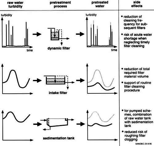
Fig. 44 Role of Sedimentation Tanks,
Intake and Dynamic Filters in Raw Water Pretreatment
|
Run Down Sedimentation Tank Impairs Roughing
Filter

Run Down Sedimentation Tank
Impairs Roughing Filter
The village of Plumbon lies on the northern coastal plain
of a large Asian island. Owing to the saline groundwater, surface water from the
river Cimanuk is used as raw water source. Since the village is situated in the
lowlands water has to be pumped in three stages; i.e., raw water is pumped to a
sedimentation tank located next to the river, the presettled water is then
lifted to the treatment plant comprising two roughing and one slow sand filter.
unit, and the treated water is then conveyed to an elevated tank supplying the
3,000 inhabitants of Plumbon.
The water level of the Cimanuk river increases by more
than 2 m in the rainy season. During this period, the raw water contains very
high and fluctuating loads of suspended solids, as well as turbidity peak values
of more than 4,000 NTU. Extensive erosion causes an important sludge flux on the
river teed, and it is estimated that the Cimanuk river creates every year 10,000
m² of new land around its estuary. The raw water intake is fixed and the
inlet is always on the same level. This leads to a high load of settleable
material in addition to the suspended solids always present throughout the
year.
The water is pumped into a sedimentation tank which is
also used for balancing purposes between the first and second pumping stage.
Originally, the tank was 2 m deep, however, since it has no draining facilities,
the sludge accumulating in the tank has never been removed. Therefore, the wafer
depth in the tank currently amounts to only 0.5 m. Furthermore, the compartment
of the first and second tank is by-passed by a pipe leading the raw water
directly into the last section of this "sedimentation tank".
Owing to the lack of pretreatment, untreated raw water is
pumped to the roughing filters which are unable to meet this heavy silt load.
The filters are cleaned hydraulically every three days, however, they had to be
cleaned manually after filter operation of only seven months. This cumbersome
work was repeated a second time, thereafter, the caretakers refused to carry out
this senseless job. Meanwhile, different studies on filter improvement
alternatives were carried out by students at the treatment plant. However, an
appropriate design, construction and operation of a new sedimentation tank is
the key to rehabilitate Plumbon's water treatment scheme. |
13. Construction of roughing filters
As a matter of principle, local material, manpower and
community participation should be used, whenever possible, in the construction
of any water supply scheme in developing countries. The initial costs might
be higher than for package or conventional water treatment systems, however,
with the construction of roughing and slow sand filters, most capital costs flow
back into the local economy. Furthermore, use of local material and manpower is
also important with regard to maintenance, repair and extension work, since
these resources will remain available even after completion of the treatment
plant. The filter structures should be simple, sturdy and of good finish to
guarantee their long-term use and reduce future maintenance and repair costs.
The layout should facilitate both operation and maintenance.
Local climate and a varying relationship to time will be the
determining factors for the construction schedule. Project implementation
should be initiated long before site clearance and excavation are started.
Ideally, the project engineer should be called by the village after the
community's decision to improve the water quality supplied by the system in use
or to construct a new water supply. Quantity and quality of potential water
sources will then have to be assessed. At this point, the engineer must be aware
that a water treatment plant is usually the most complex component of a
simple water supply system. Once again we refer to the saying: "the best
treatment is no treatment". Use of a remote spring instead of nearby surface
water should be taken into consideration. If the community has to rely on
surface water, the water treatment project will have to start monitoring the raw
water quality, especially during the rainy season. The subsequent dry season
will be used to design the treatment plant, estimate the construction costs and
secure the financial resources. Organisation of construction work and final
preparations should be started during the following rainy season and prior to
the actual construction work, which will be initiated during the following dry
season; i.e., two years after the community's request for support regarding
improvement of its water supply. However, this project preparation largely
depends on the way the community discusses the project, decides upon it and
organises its contribution in cash and kind. Project preparation quite often
takes more than two years, a time span which is not lost if the project can
be realised on a strong communal basis. Good site organisation and availability
of building material will have a positive influence on the progress of
construction work, which can often only be carried out during the dry season
when community participation is most likely and climatic conditions favourable.
Therefore, large structures might require an additional two or more dry
seasons.....- calculation of the total time required by a project is left to the
reader.
Sound design, good construction quality and ownership
development by community participation are necessary prerequisites to achieve a
well-operated treatment plant. Much depends on available skills, on the
quality of the material used, and on supervision during construction. A number
of key issues need to be considered during the planning and design phase, such
as type of locally available material, local construction technique, such as
skills with masonry structures, access to the planned treatment plant site, as
well as topographic and soil conditions. An experienced construction foreman and
regular site inspections by the design engineer will contribute to improve the
quality of the structures. Particular attention should be paid to the mixing,
compacting and curing of concrete, as this largely determines sturdiness, water
tightness, and durability of the structures. Since a water supply should last
for more than two generations, during which time the structures are likely to be
exposed to adverse climatic conditions, good quality structures are
absolutely
necessary.
13.1 Filter box
Filter structures can generally be located below or above
ground, as illustrated in Fig. 45. The respective choice depends on soil
characteristics, available construction material and hydraulic profile. On a
flat surface, gravity flow often requires the structures to be placed below
ground. This, however, might cause some problems or additional costs for
adequate drainage of the washwater. A partially buried filter will require less
excavation work and provide support to the sidewalls by the back-filled soil.

Fig. 45 Location and Materials of
Roughing Filter Boxes
Roughing filters are usually shallow structures of about
0.6 m (intake and dynamic filters) to 1 - 2 m (roughing filters). The size of
the filter box is dependent on hydraulic capacity (see also Section 9.4) and
filter length. The filter boxes should not be too big (maximum filter area for
vertical-flow roughing filters should amount to 25 30 m², maximum cross
section area for horizontal-flow roughing filters about 4 - 6 m²), to avoid
problems with high washwater discharge rates. Furthermore, the filter box should
also not be too high (preferably around 1 m) to allow easy removal of the filter
material during manual cleaning.
A trench excavated in impervious soil, such as clay, silt or
lateritic ground, presents a low-cost solution for a filter box. The trench
has sloping sidewalls which do not exceed the slope stability of the
water-saturated soil (slope less than 1:1). Lining of the base and sidewalls
prevents clean filter material from mixing with the surrounding ground. A layer
of sand, prefabricated slabs, in-situ applied coatings (concrete lining,
ferro-cement, lime mortar) or in exceptional circumstances (e.g. refugee camps),
prefabricated plastic linings or the use of geotextiles, are the most
appropriate materials to use.
A watertight box has to be constructed in permeable ground or
if the filter is installed above ground. In such cases, vertical sidewalls
are recommended. Burnt clay bricks with cement mortar lining, concrete bricks or
reinforced concrete should be used for such filter boxes. The foundation and
floors of the box need special attention to avoid cracks caused by uneven soil
settlement. Finally, watertight expansion joints will probably have to be made
for long filter boxes constructed for horizontal-flow roughing filters.
Alternatively, long filter boxes resting on difficult ground can be split into
two or more separate units with flexible pipes interconnecting the compartments.
U-shaped units can also reduce the total length of filter boxes. In such a
layout, inlet and outlet are to be placed on the same filter side, and the box
divided into two equal parts by a longitudinal separation wall.
The filter box should be tested for watertight-ness,
preferably before it is filled with filter material. Leaks can be detected
and repaired more easily in an empty structure. Special attention must be paid
to the joints at the floor-wall interface or the inlet and outlet boxes fixed to
the filter box. Watertight joints require water stoppers made of PVC or rubber.
Other weak points in the structure include the pipe sealings which possibly need
additional reinforcement to prevent cracking of the walls, and seep rings to
prevent
leaks.
13.2 Filter material
The filter material should have a large specific surface
to enhance the sedimentation process taking place in the roughing filter,
and high porosity to allow the accumulation of the separated solids.
Generally speaking, any inert, clean and insoluble material meeting the above
two criteria can be used as filter medium. Filtration tests revealed that
neither the roughness nor the shape or structure of the filter material have a
great influence on filter efficiency [10]. The following material could
therefore be used as filter media:
· gravel from a river bed
or from the ground
· broken stones or rocks
from a quarry
· broken burnt clay
bricks
· plastic material either
as chips or modules (e.g. used for trickling filters) may be used if the
material is locally available. Attention has to be paid to the uplift forces of
the water
· possibly burnt charcoal,
although there is a risk of disintegration when cleaning the filter
material, it should only be considered in special cases (e.g. for removal of
dissolved organic matter)
· possibly
coconut fibre, however, due to the risk of flavouring the water during long
filter operation, it should be used with care.
|
Every Day and Every Kilogram Count
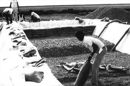
Every Day and Every Kilogram
Count
I was about to go for lunch when the phone in my office
rang. Peter, a former working colleague, was at the other end. With the same
enthusiasm as in critical situations, I was informed that his office was
contracted by the Disaster Relief Unit to design and construct a water supply
system for a resettlement camp in East Africa. The camp should host 20,000
refugees and the infrastructure should consist of simple shelters, a feeding
centre, a small hospital, water and sanitation facilities to be set up as soon
as possible. Peter needed technical advice on the design of the water treatment
plant which had to meet special construction criteria; i.e., installation time
and weight of building material had to be kept to a minimum.
After the call, I had my lunch in the train heading
towards the capital where I met Peter in his office early afternoon to discuss
the water supply project. The raw water had to be pumped from a large irrigation
canal whose water quality was unknown but rather turbid looking. Cement is
rather expensive and often scarce in that country. We sat between drawings,
reports and computers and looked at each other waiting for a stroke of genius.
Meanwhile, the water of a small biotope in the back garden was reflecting the
sunlight of the warm summer afternoon. Peter suddenly got enthusiastic again and
proposed to use the "biotope construction technique". The rest of the design was
completed within a short time.
Two weeks later, Toni volunteer of the Disaster Relief
Unit and construction foreman, was sitting in a cargo aircraft heading for
Africa. The aircraft also carried a number of large plastic sheets and different
plastic fittings which were unavailable in the country of destination. Soon
after his arrival, Toni started construction of the treatment plant with about
100 casual labourers, and within six weeks the pumping station, two
sedimentation tanks, four horizontal-flow roughing filters and the treated water
reservoir were set up. The tanks and filters were designed as earth basins with
inclined walls and earth dams made of bags filled with the excavated soil. The
basins were then coated with the prefabricated plastic linings. Perforated pipes
were laid in the roughing filters to allow hydraulic filter cleaning. Trial
operation of the treatment plant revealed a satisfactory efficiency; i.e., the
raw water turbidity of 1,000 2,000 NTU was reduced to half of its initial value
by the sedimentation tanks, and turbidity in the effluent of the roughing
filters was recorded at 5 - 20 NTU.
The infrastructure of the refugee camp was then handed
over to the local Commissioner for Refugees. However, political disputes about
implementation and use of the camp started among the countries involved soon
thereafter. Finally, 5,000 refugees settled almost two years after completion of
the camp and reminded Toni of an experience he had during construction. A local
foreman had told him: "You have a watch but I have the time .... ".
|
Gravel is the commonly used filter material but it was
replaced by broken burnt bricks in the horizontal-flow roughing filters
constructed by the Blue Nile Health Project in the Sudan [55], by palm fibre
called "ijuk" in a roughing filter project in Indonesia [45], and by plastic
material in laboratory tests at the University of Newcastle in England [45].
Table 6 shows that filter efficiency of bricks and plastic as filter material is
similar to gravel with respect to turbidity reduction. The filter filled with
palm fibre has a better respective performance compared to the gravel filter.
Greater porosity (92% versus 37%), responsible for the reduction of the
effective flow velocity, is certainly an explanation for this observation.
However, since use of the palm fibre caused a considerable drop in the dissolved
oxygen concentration, odour and taste problems could occur. Therefore, more
detailed investigations are always necessary before palm fibre or any other
alternative material is used on a long-term basis.
Roughing filters are usually composed of three filter
fractions ranging in size from coarse to fine. The coarse and a large amount
of the finer suspended solids are removed by the first filter pack. Since a
large pore volume is required in this part of the filter, a coarse filter
material is best installed over a considerable filter length. The subsequent
filter material is finer and the packs installed over a shorter filter length.
The last filter fraction of limited length should assume only a polishing
function as it is supposed to remove the last traces of the finest suspended
solids found in the water.
Table 6 Relative Filter Performance with Different Filter
Material (parallel tests)
|
Turbidity reduction (size of filter material) |
|
Project |
Gravel |
alternative filter material |
|
burnt bricks, BNHP/Sudan [55] |
87 % (20-30, 15-20 and 5-10 mm) |
77 % (bricks 30-50, 15-20,5-10 mm) |
|
palm fibre* Plumbon/Indonesia [57] |
39 % (16-25 mm) |
67 % (fibre) |
|
plastic material, University of Newcastle [45] |
92 % (broken bricks, 30-50 mm; gravel 14-18 and 5-9 mm) |
94 % (rings F 38 mm pipes F 30 mm caps width 5 mm) |
*only filled in first filter compartment
Since filter efficiency increases with decreasing filter
material, one is tempted to use the smallest possible filter material or
even to omit the larger filter material and to install only one the finest -
filter medium. However, the roughing filter technology requires coarse filter
material as denoted by its name. The finest filter material should not be
smaller than about 4 mm to ease hydraulic filter cleaning. Filter material which
is too coarse, however, has a smaller filter efficiency and would therefore
require a longer filter length to achieve the same turbidity reduction. As
already illustrated by Fig. 31, use of at least two or generally three
different filter material sizes will result in an economic filter design and
adequate filter operation.
Table 7 Guidelines on Size and Length of Filter Material for
Different Types of Raw Water
|
|
|
filter length of 3 fractions |
|
type of solid matter |
filtration rate VF |
gravel sizes of 3 fractions |
upflow roughing filter in layers |
upflow roughing series |
horizontal flow roughing: filter |
|
settleable solids |
|
16 - 24 mm |
40 - 80 cm |
|
|
|
0.6 - 1 m/h |
12 - 18 mm |
20 - 30 cm |
|
|
|
|
8 - 12 mm |
20 - 30 cm |
|
|
|
suspended solids. |
|
12 - 18 mm |
40 - 60 cm |
60 - 120 cm |
200 - 400 cm |
|
4 - 0.8 m/h |
8 - 12 mm |
30 - 40 cm |
60 - 120 cm |
100 - 300 cm |
|
|
4 - 8 mm |
30 - 40 cm |
60 - 120 cm |
50 - 150 cm |
|
plankton, algae |
|
8 - 12 mm |
30 - 50 cm |
|
|
|
0.3 - 0.5 m/h |
4 - 8 mm |
30 - 50 cm |
|
|
|
|
2 - 4 mm |
30 - 50 cm |
|
|
Table 7 lists some general guidelines on size and length of
different filter fractions. These guidelines should not be followed too
rigidly. Practical aspects, such as e.g. availability of specifically graded
material from a quarry, are more important. If adequately graded filter material
is not available, gravel at the construction site can also be sieved through
wire meshes or perforated steel plates used as sieves.
During the initial development phase of the horizontal-flow
roughing filter technology, the Asian Institute of Technology (AIT) in Bangkok
recommended the installation of six to eight small gravel layers [58]. Gravel
size should subsequently be reduced from 20 to 2.5 mm and thereafter increased
again to 25 mm. There is no reason why the smallest gravel fraction should be
located in the centre of the filter bed since the following gravel packs have,
by nature, a smaller removal efficiency.
The filter media used for roughing filters has to be clean
and free from organic material. It is therefore important to wash the
aggregates thoroughly in order to remove all loose and dirty material from the
surface of the filter media. If this recommendation is not followed, the
effluent quality of the roughing filter will be poor and result in rapid
clogging of the slow sand filter.
The different filter fractions should be separated from each
other to avoid mixing of the aggregates during manual filter cleaning. The
filter material of an upflow roughing filter in layers is preferably separated
by a plastic wire mesh. The different filter media of roughing filters in series
are separated by the different filter boxes, and perforated separation walls are
used for that purpose in horizontal-flow roughing filters. Burnt brick or cement
block walls with open vertical joints are best suited for separating the filter
fractions. The total area of the open joints should ideally amount to 20 to 30%
of the total filter cross section and be equally distributed over the entire
cross section to maintain an even flow throughout the horizontal-flow roughing
filter. Prefabricated perforated bricks or blocks (e.g. holes F 3 cm, spacing 5
x 5 cm) or loose rubble could be installed instead of open joints. Simultaneous
filling of filter material in layers must be observed with loose or weak
separation wall
structures.
13.3 Inlet and outlet structures
Inlet and outlet structures are necessary to regulate the
flow, evenly distribute and abstract the water, and to control the water level
in the filter. The inlet and, preferably, also the outlet are equipped with
V-notch weirs for flow control if weir overfalls of about 20 - 30 cm can be
accommodated in the hydraulic profile of the treatment plant. The V-notch weir
at the outlet can be omitted in treatment plants with a small available
hydraulic head and replaced by an effluent pipe which will maintain the water
level in the filter at a minimum height. A flow rate control allowing
accurate flow adjustments should always be installed at the inlet of roughing
filters. A flow rate control at the filter outlet is not recommended as
backwater effects create flow adjustment difficulties. An inlet weir can control
the headloss and the water level increase in the inlet box located after the
weir also indicates filter resistance development.
Even flow distribution through the filter bed is achieved
either by a false filter bottom or by perforated pipes in upflow roughing
filters, and by an inlet chamber with a perforated separation wall in
horizontal-flow roughing filters. Fig. 46 illustrates the inlet and outlet
structures of a horizontal-flow roughing filter. The middle part of the
separation wall next to the inlet chamber should be perforated. A full wall at
the bottom and at the top respectively, prevents coarse settled solids or
floating matter from penetrating into the filter. The minimum width of the inlet
chamber should be at least 60 to 80 cm for easy removal of settled matter. A
similar outlet chamber is installed in horizontal-flow roughing filters at the
effluent side. However, the openings in the separation wall after the last
filter pack are distributed throughout the filter cross section. It is
important to protect the pretreated water from algal growth or from airborne
pollution. For that purpose and to avoid mosquito breeding, horizontal-flow
roughing filters have to be filled to about 30 to 40 cm above the effluent weir
level with filter material, and the outlet chamber must be covered. In upflow
roughing filters, the effluent pipe located roughly 5 cm above the top of the
filter bed, controls the water level. This free filter water surface should also
be protected by a layer of large stones (about F 50 - 80 mm, height 20 - 30 cm)
or by a removable roof cover.

Fig. 46 Inlet and Outlet Structure of
a Horizontal-flow Roughing
Filter
13.4 Drainage system
Roughing filters can be cleaned either hydraulically or
manually. Drainage systems with a high hydraulic capacity and capable of
abstracting the wash water evenly from the filter bed are necessary for
hydraulic filter cleaning. Fig. 47 contains different drainage layouts. The
installation of a false filter bottom is the best option for vertical-flow
roughing filters. About 10-cm high concrete blocks support the perforated
filter bottom made of roughly 5-cm thick concrete slabs and perforation holes of
about 6 - 8 mm diameter. These slabs are usually installed with open joints of
about 4 - 8 mm clear width. Perforated drainage pipes or perforated culverts
have to be used in horizontal-flow roughing filters and could be a possible
alternative to a false filter bottom in vertical-flow roughing filters. However,
a false filter bottom cannot be used in horizontal-flow roughing filters as it
would lead to water short circuits. Therefore, perforated drainage pipes and
culverts will also have to be installed every 1 to 2 m perpendicular to normal
flow direction. Since intake and dynamic filters are surface filters, the sludge
which mainly accumulates on top of the filter bed is cleaned manually.
Therefore, these filters do not require drainage installations with a high
hydraulic capacity.
Pipes and shutoff devices are required for hydraulic filter
cleaning and for complete dewatering of the filter box. Large pipe diameters
of 150 to 250 mm are necessary for efficient hydraulic cleaning. The hydraulic
capacity of these installations should allow an initial filter drainage velocity
of 45 - 90 m/in. The outlet of drainage pipes should be located at the lowest
possible level in order to make optimal use of the available hydraulic head. For
cost reasons, these large diameter drainage pipes should be as short as possible
and firmly fixed to the structures in order to withstand the considerable
dynamic pressures generated by the flushing cycles. A manhole, as shown in Fig.
48, can be used as interconnection between filter bottom and drainage pipe to
alternatively reduce the length of the hydraulic drainage pipes. In contrast to
these large pipes, small tubes of 1 - 2 inches in diameter sealed by nipples
will adequately dewater the different compartments (inlet, filter and outlet
boxes) of a roughing filter. Small structures, however, can also be dewatered
with the help of buckets or a tube used as a siphon.

Fig. 47 Layout of Different Drainage
Systems for Roughing Filters
Fast opening devices are required to initiate a fast
hydraulic cleaning cycle in order not to lose too much washwater during
cleaning. These devices should be simple in design, sturdy and easy to
operate. In the long run, they must be watertight and equipped with a
shut-off device to interrupt the drainage process. Use of butterfly valves is
the best but most expensive option. To reduce construction costs, different
local designs of fast opening devices have been developed as illustrated in Fig.
34 on page IX-9. A good example of an appropriate technology is the modified
milk can cover developed by CINARA in Colombia. ZHAS in China successfully uses
a self-designed plug valve installed in a steel box, and Helvetas in Cameroon
applies carefully shaped and firmly installed plugs held by a removable bar.
Fig. 48 Levelling of the Drainage
System
Finally, structures for fast drainage and safe washwater
disposal must be provided. The washwater is generally discharged into an
open canal used to convey the hydraulic flush to a nearby surface water or to a
small pond used for intermediate storage. Construction of a small lagoon is
recommended to recover the solid matter washed out of the filter for use in
agriculture. Direct discharge of the washwater in stagnant surface water may
gradually silt up the reservoir and adversely affect its water
quality.
13.5 Gravel and sand washing facilities
Filter material needs to be carefully washed before it is
placed into the roughing and slow sand filters. The gravel and sand must be
free from organic material, silt and clay particles, as these impurities cause
serious operational problems. The organic matter could decompose and affect
taste and odour, and the particles slowly washed out of the filters could thus
increase turbidity of the treated water. It must be noted that provision and
cleaning of filter material by the community require considerable effort and
time.
Filter material washing is best achieved by mechanical
stirring of the aggregates in a washwater basin, as mechanical friction rubs
the impurities off the aggregates' surface. The washing site should be located
in the centre of the treatment plant, preferably next to the slow sand filters
which are cleaned manually and more frequently to reduce the transport distance
of the filter material. The site should also not be too small and allow 4 - 6
men to wash the filter medium simultaneously. Washwater can be saved and gross
impurities eliminated if small filter material loads are stirred and removed
with a shovel to a first tank before they are transferred to a second tank for
final washing. Such a washing installation is illustrated in Fig. 49. However,
centralised cleaning involves transport of the filter material. Use of the open
drainage channel located along roughing filters is an alternative to the washing
site as it requires less gravel movement.
Raw water of moderate turbidity can be used as washwater,
and prefiltered water for final sand cleaning. A flexible hose may also be
used to wash the filter material, and should thus also be available if raw water
is supplied by gravity to the treatment plant. The washing site may also be
equipped with a shower for the treatment plant operator if the washwater is
adequately disposed.
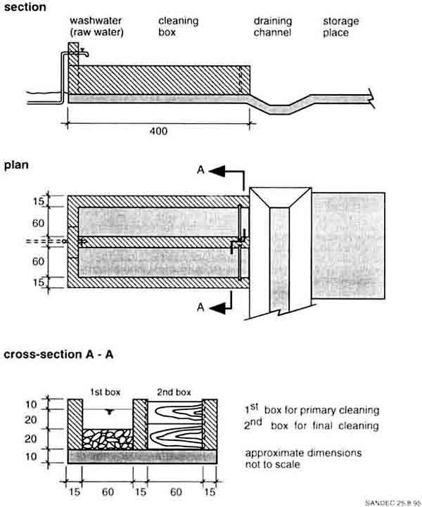
Fig. 49 Layout of Gravel and Sand
Washing Installation
|
A Precious Plastic Sheet
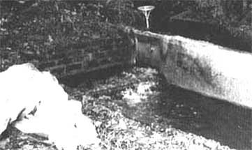
A Precious Plastic
Sheet
This was already my fourth visit to La Javeriana treatment
plant which forms part of the water supply system of a private education centre
in a rather large and well-known city in Latin America. I have always looked
forward to meeting Alcibiades, the dedicated caretaker of the treatment plant. I
enjoyed our interesting discussions and Alcibiades would quite often relate some
of his new practical experience he gained since my last visit, or we discussed
some pending operational problems for which we found appropriate solutions. We
learned a lot from each other, and our working relationship grew into a personal
friendship.
Since my visit last year, new houses had been constructed
in the catchment area. This further enhanced soil erosion in the rainy season,
and uncontrolled wastewater discharges into the rivulet deteriorated the raw
water quality especially in the dry season. Alcibiades had to install a small
grit chamber in front of the intake filter to reduce the silt load on the
filters. He also tried to reduce the increasing bacteriological pollution by the
installation of a sand layer in the roughing filter. The first alteration
brought the expected amelioration, however, he faced considerable problems with
the second modification. The sand layer, which developed a significant filter
resistance in the roughing filter, resulted in filter clogging. Since hydraulic
cleaning was no longer possible, the roughing filter had to be cleaned
manually.
La Javeriana's treatment plant is located on a slightly
sloping meadow in a picturesque environment - reason enough to make some photos
for my project documentation. I had intended to document the recent changes at
the intake filter with some snapshots. What I discovered was a carelessly
disposed of plastic sheet near the intake filter, and I was surprised by this
litter that did not at all correspond to Alcibiades' working manner. He normally
kept the treatment plant and its surrounding in very clean condition. I thought
of several reasons for his negligence; i.e., his salary may no longer meet the
current standard of living, or he may have personal problems with the
administration vat home.
I was about to take away the unpleasant plastic sheet
which would had spoiled my photo when Alcibiades arrived on the scene. I told
him my problem and asked him to remove the plastic. However, Alcibiades was
strongly opposed to my suggestion since this piece of plastic was used to clean
the entire filter box during the biannual removal of the gravel from the intake
filter. The plastic sheet was used as temporary slab in order not to soil the
cleaned gravel. Ashamed of my ignorance I took a picture - along with the
plastic sheet right in the middle of the photo! |
14. Operation and maintenance of roughing filters
Nowhere in the world will a water treatment run by itself.
An input of manpower will always be necessary. Right from the beginning of
project implementation, operational and maintenance aspects require careful
elaboration and approval of the different parties involved, such as the Ministry
of Water, support agencies, and the community. A village water committee is
usually formed to manage a water supply scheme. However, the caretaker plays
a key role in the operation and maintenance of a water supply. He and his
colleagues are normally elected by the water committee which also clearly
defines their duties and working conditions, such as salary, fringe benefits,
etc. The major tasks of a caretaker at the treatment plant is to control the
water flow, monitor the quality, clean the filters and carry out general
maintenance work. These activities will be described in the following sections.
Main responsibility for operation and maintenance of a water
supply scheme must be given to the community concerned, since reliability of
a water supply primarily affects its inhabitants. In other words, the water
supply system has to be operated and maintained at village level as much as
possible, using locally available resources and infrastructure. Roughing and
slow sand filters meet these criteria as they do not require chemicals,
mechanical spare parts or highly trained staff. Ownership and self-management of
a water supply by a committed community prevents project failures and waste of
public
funds.
14.1 Caretaker training
Comprehensive training of local staff is essential since
technical installations must be run by operators. While most technical problems
can be eliminated or reduced by appropriate design and construction, human
aspects which might affect treatment plant operation are more difficult to
control. Careful, formal training of caretakers and extensive support, guidance,
and supervision in the first years of operation are necessary.
Adequate payment of the local staff is equally important.
The caretaker of a rural water supply usually has numerous duties; he is
often in charge of treatment plant operation, maintenance of the water
distribution system, collection of water taxes, clearing irregularities and
complaints, etc. Motivation alone will not keep him on the job; his or her work
must be adequately compensated.
The caretaker should be recruited from the local village,
he should preferably be settled, married, land owner and well-recognised by
the community. Ideally, he should also have some technical skills, however,
interest and motivation to run a water supply system are more important criteria
for his election. He should show his interest and skills during construction of
the treatment plant. However, the future caretaker should preferably not be
selected during the construction phase of a project but after assessment of the
performance of different candidates during this period by the construction
foreman and the design engineer who could then propose qualified candidates to
the water committee for election. Each caretaker must also have a deputy
who can assume operation of the water supply during his absence for reasons
of illness, personal matters or other obligations. However, responsibilities of
the different staff must be clearly defined and separately developed for each
employee.
Formal caretaker training is best carried out by the
executing agency and conducted in the local language. Annex 7 outlines a
possible training programme. Formal training will be complemented by on-site
instructions given by the design engineer. Each treatment plant is different and
thus requires the development of individual operation schedules that will have
to be elaborated jointly with the supervisor in the first year of operation and
reviewed regularly on the basis of the treatment plant performance. Caretaker
training is a continuous process. Regular meetings with other caretakers is
an ideal platform to exchange experience, enhance reputation and value the
importance of the caretaker's inconspicuous daily
activities.
14.2 Treatment plant commissioning
Filter operation should only start when construction work has
been properly completed. For instance, performance of a horizontal-flow
roughing filter only partially filled with gravel will be poor. The water
bypasses the impounded gravel layers in such a way that the unit will not act as
a filter but as an inadequate sedimentation tank. Emphasis must therefore be
placed on a good finish of the construction work, including the installation of
proper flow control and drainage facilities, as well as the full supply of
filter material. Once the treatment plant is in operation, provision and
installation of missing filter material have repeatedly proved impossible as the
construction partners might refuse to assume additional work. Subsequent filling
of the remaining filter medium could also impair plant performance.
Cleaning of the installed filter material by the drainage
system is recommended before starting filter operation. The roughing filters
should be filled with water up to the effluent weir level at low flow rates of
0.5-1 m/in. Thereafter, the water is drained off by the first drainage
installation situated next to the inlet. Any dust on the surface of the filter
material is rinsed to the filter bottom. Impurities accumulated near the
drainage system will be flushed out of the filter If necessary, this procedure
will have to be repeated two or three times changing the point of drainage from
filter inlet to filter outlet. Such filter cleaning will prevent dust particles
from settling on the fine gravel fraction and increasing the initial filter
resistance. Operational control of the complete drainage system is a positive
side effect of the described cleaning procedure.
Project hand over is often combined with the inauguration of
the installations. A supply of clean and sufficient water on this special
day should be guaranteed. Water treatment operation has to start about two to
three months prior to the official inauguration day to ensure a sufficient
supply of good quality water and to avoid disappointing the community and the
invited guests. The treatment plant may at first not produce the expected water
quality, as the biological processes, known as filter maturation, will
require some time to develop (a few weeks or months) depending on the raw
water characteristics. The treatment plant may be operated at reduced capacity
during this period. Pretreatment may be bypassed to accelerate slow sand filter
maturation. However, this procedure should be applied only to slightly turbid
raw water carrying dissolved organic matter which will not be reduced by the
prefilters but used for the development of the "Schmutzdecke" in the slow sand
filter.
14.3 Flow control
A 24-hour continuous filter operation makes maximum use of
the installations. Continuous and constant flow conditions usually improve
treatment plant performance and reduce the required structure size. However,
gravity flow is usually necessary for such ideal situations. Continuous flow
might not be possible in water supply schemes where the raw water has to be
pumped. When pumping is required, the treatment plant might be staffed for 8 or
16 hours a day, depending on whether one or two shifts are available.
Intermittent slow sand filter operation is not recommended
for quality reasons. In order not to affect the biological activities in the
slow sand filter, this filter can be operated at a declining filtration rate in
pumped systems during the unstaffed period of the day. In practice, the stock of
supernatant water is drained through the filter at a continuously declining flow
rate during the night and in the morning hours, the filter is refilled with
pretreated water to reassume normal operation. Such an operation calls for
special provisions as pretreated water for the slow sand filter has to be
provided at higher pumping rates.
Roughing filters are mainly physical filters. They are less
affected by flow interruptions as they do not depend on a continuous supply
of nutrients as biological filters. Hence, intermittent operation can be applied
without causing a significant deterioration of the prefiltrate, provided smooth
restarting of filter operation is observed. Declining filter operation rate of
roughing filters to supply slow sand filters with a constant flow is not
advisable due to the relatively small water volume stored in the prefilters.
The most favourable option in a pumped scheme is the provision of a raw water
balancing tank which allows continuous filter operation. Removal of the
coarse solids is a positive side effect of such a tank. The different tank
volumes required for a 100 m³/d plant are illustrated in Fig. 50.
|
A Goat and a Bag of Sweet Potatoes
Ngondzen was the fourth water supply system I visited on
that day and Ndzenshwai was the last scheme before reaching the hotel in Kumbo,
a small district town in West Africa. Tired from the heat and dust, I really
looked forward to the evening shower and probably also the entire crew in the
four-wheel drive project car. As we entered Nongdzen at rather high speed, the
project coordinator suggested to see the caretaker of the treatment plant at
once in order not to lose too much fume. Neither Mr Boniface, the local
technician, nor I had any objections to his suggestion. As we crossed the
junction next to the church we saw a large crowd of people. We assumed that a
wedding was being held and drove on to the caretaker's house. However, the
chairman of the water committee ran after our car and tried desperately to
attract our attention. This is when our schedule got mixed up.
The crowd in front of the church was not celebrating a
wedding but had been waiting for us for three hours. We reversed the car and
drove it to the church, where a local group of drummers started pounding on
their instruments as we were directed to chairs in front of the community hall.
The welcoming address was well-prepared, typed on a piece of paper bearing three
official stamps, and read by Mr Patrick, the chairman of the water committee.
Two dancing groups performed traditional dances after his speech. Thereafter, a
colourful cap was placed on my head and I was nominated chief of the village and
loudly applauded by the entire community. While another dancing group was
starting its performance, a traditional gift commonly donated to chiefs was
conferred on me - a goat! Headed by Mrs Dominica, chairperson of the women's
group, a cozen women started to dance and deposit a bag filled with sweet
potatoes in front of my feet. Overwhelmed by so much of honour, I addressed a
word of thanks to the villagers and stressed the importance of maintenance in a
water supply scheme.
Mr Boniface, the local technician, was sitting quietly
next to me during the entire ceremony. We were then served local dishes and
brews in the community hall and more toasts were exchanged. It was late
afternoon as we climbed into our project car, the goat attached onto the roof
rack and the bag of sweet potatoes loaded in the rear. After cheerfully waving
goodbye to the villagers, we left Ngondzen. However, the new chief who was
sitting next to Mr Boniface felt embarrassed because he had won, during the
two-hour celebration, all the praise for the efforts made by the local
technician to mobilise the community, to organise construction material and to
supervise this self-help project - a work which had kept him busy for the last
two years. We looked at each other without exchanging a word but the message was
clear.
The goat and the bag of sweet potatoes were unloaded in
front of his home before we drove on to our hotel under a shining moon.
|
The flow through roughing filters is controlled by a flow
control device at the inlet and by a fixed weir at the outlet as illustrated
and recommended in Fig. 32 on page IX-7. This is also true for the recommended
inlet controlled slow sand filters which compensate the progressive headloss
development by a gradual increase of the supernatant water level. For gravity
schemes, constant feeding is maintained by a more or less fixed position of the
valve in the supply pipe and a subsequent overflow in the distributor box. For
pumped schemes with a raw water tank, the flow to the treatment plant is
regulated by a mechanical flow rate device as shown in Fig. 33. These two main
possibilities are illustrated in Fig. 21 on page Vl-9.
V-notch weirs are generally used for discharge measurements.
Permanently installed V-notch weirs or transportable equipment used for flow
control are described in Annex 2. The flow rate through each filter should be
routinely controlled once a day if V-notch weirs are installed, and with
transportable equipment at least twice a week according to the monitoring
programme outlined in Annex 8.
Filter resistance in roughing filters is minimal and hardly
reduces the flow through the filter. The headloss increases to a few
centimetres in well-operated roughing filters. Filter resistance builds up along
the entire filter bed as roughing filters act as space filters. It is reduced to
its initial value by efficient and regular filter flushing. However, intake
and dynamic filters can build up considerable filter resistance as they
mainly act as surface filters. Since the headloss in intake filters can increase
to 20 - 30 cm within a week [48], the flow through the filter has to be adjusted
by gradual opening of the valve located in the effluent pipe. Dynamic filters
have to produce by definition a high filter resistance within a short time
during periods of high raw water turbidity. This will clog the filter bed and
prevent highly turbid raw water from flowing to the subsequent filters. Intake
filters are usually cleaned once a week, and dynamic filters after every high
turbidity peak.
Filter resistance can easily be determined by measuring the
level of the free water tables in the inlet and outlet chamber of roughing
filters. The effluent's weir crest level can be used as reference (0-level).
Gauging rods fixed to the walls of these two chambers will facilitate the
respective
measurements.
14.4 Water quality control
A water quality monitoring programme usually aims at:
· characterising the raw water
quality
· establishing and monitoring
treatment plant performance
· developing operational
criteria for the roughing filters and slow sand filters (i.e., schedule for
filter regeneration/cleaning)
· optimising layout and
operation of the filters (i.e., exchange of filter material, increase or reduce
filtration rate).
The most important quality criteria for drinking water is its
bacteriological quality. However, improvement of the bacteriological water
quality greatly depends on raw water turbidity, efficiency of the pretreatment
units in reducing this turbidity, and on adequate slow sand filter operation.
Turbidity and bacteriological contamination of the water are, therefore, the key
parameters for rural surface water characterisation. Turbidity measurements play
a major role in monitoring the pretreatment step(s), slow sand filter efficiency
is usually established by bacteriological tests.
However, bacteriological water quality examination requires
special equipment, specific field test kits or generally the infrastructure
of a laboratory. Well-trained and experienced staff are essential for a reliable
analysis. Routinely performed bacteriological water quality tests of rural water
supply schemes are generally far beyond the capacity of the responsible
institution and, therefore, mostly restricted to random tests. A well-operated
slow sand filter is a stable and reliable water treatment unit not requiring
frequent bacteriological tests. In practice, test frequency can be reduced to a
minimum once the bacteriological efficiency of the slow sand filter is
established. Headloss development and length of filter run are appropriate
criteria to assess the bacteriological efficiency of slow sand filters.
Well-operated slow sand filters use natural treatment processes, and nature
will rebel with a headloss increase when filters are overloaded, in contrast to
chemical and mechanised treatment processes, where chemical doses and water
pressure can often be increased at the cost of the water quality produced. The
caretaker may thus greatly influence and control the quality of the treated
water by adequate slow sand filter operation and by monitoring the headloss
development.

Fig. 50 Required Tank Volume of a
100m³/d Treatment Plant in Correlation to the Flow Pattern
Turbidity measurements are in principle simple and can,
therefore, be handled by the local caretaker. However, regular conventional
turbidity measurements, although theoretically simple, may be difficult to carry
out in rural areas. Transport and communication problems, the fragile nature of
delicate instruments and the difficuIties with regard to commodities supply
(e.g. batteries, standards), are aspects which may lead to possible failures of
the most simple turbidity monitoring programme. Sturdy and simple field test
methods have therefore been developed to allow characterisation of mainly
physical water properties under actual field conditions. Although the different
methods described in Annex 1 will not provide absolute but relative values, they
are, however, a useful tool for water quality description of any specific
treatment plant.
A simple turbidity test tube developed by DelAgua [7]
replaces the common turbidity meters which usually require a power supply. Since
the visual method is dependent on the sensitivity of the eye, it is not as
accurate as electronic systems, especially in the high turbidity range. The
lower practical limit of the tube can measure five TU (Turbidity Units) and
therefore meets the turbidity standard required by slow sand filtration.
The filterability test roughly indicates the amount of
suspended solids in the water and can therefore be used in place of the standard
method for the determination of the suspended solids concentration which
requires a highly accurate scale, a vacuum pump and a drying furnace in an
air-conditioned room. Furthermore, modified Imhoff cones are used for the
determination of the settleable solids volume.
The stability test gives some information on the settling
characteristics of the colloidal matter and on the stability of the suspension.
The results of this test not only reflect the size and surface properties of the
solids but also the chemical and organic composition of the water. Adsorption of
Ca2+ and Mg2+ ions on suspended solid surfaces may
destabilise a suspension, while humic substances have been reported to increase,
in many instances, the stability of a suspension.
Water samples should be drawn from the raw water and from the
filter inlets and outlets as indicated in Fig. 51. Additional sampling
points may be used to optimise a roughing filter layout (e.g. by possibly
exchanging the gravel size). The efficiency of the individual filter layers can
be examined by sampling tubes installed at the end of the different filter
layers. Water sampling from these tubes should be carried out carefully in order
not to resuspend the deposits around the sampling point which would otherwise
lead to inaccurate results. Drop-wise sampling is recommended, and the first
tube of sampled water must be discarded before starting with the actual
sampling.
Simple field test equipment should be allocated to each
treatment plant. The caretaker must be properly trained in order to carry
out the different water quality tests and monitoring programme for his treatment
plant. An example of such a monitoring programme is summarised in Annex 8. The
local caretaker should be assisted and guided by a supervisor attached to the
operation and maintenance section of the governmental institution responsible
for the water supply (i.e., district or regional water administration). The
supervisor will initially carry out monthly and later biannual visits to the
treatment plant in order to support the caretaker's daily activities and provide
a feedback which will be useful for the design and operation of other treatment
plants.
14.5 Filter cleaning
Filter efficiency is not constant but may increase at the
start of filter operation and certainly decrease when solid matter accumulates
excessively in the filter. Hence, periodic removal of this accumulated
matter is required to restore efficiency and possibly hydraulic filter
performance. Filters are cleaned either hydraulically or manually, and the
cleaning methods are dependent on the way solids accumulate in the filter.
Hence, the cleaning procedures will therefore have to be adapted to the
different filters.
In intake filters, the solids mainly accumulate on top of the
filter bed. By increasing flow velocity over the filter surface, a fraction
of these accumulated solids may be dragged away by the water. However, intake
filters are usually cleaned manually with a rake and shovel once a week. The
first step in the cleaning process is the closing of the valve on the
prefiltered water line. Thereafter, the inlet control valve is opened to
increase the horizontal-flow in the filter box to about 0.20 m/s to 0.40 m/s.
The flow over the filter surface may also be increased by closing parallel
filter units and directing the total raw water flow into the unit to be cleaned.
This method is particularly advisable in systems with limited raw water supply
such as in pumped schemes or of small hydraulic pipe capacities. The solid
matter retained by the filter is first resuspended by mechanical stirring and
then flushed back to the river. Manual cleaning should start at the upper
end of the filter and continue in flow direction to avoid silting of the cleaned
gravel. The gravel of the intake filter has to be cleaned completely about once
a year. A flat concrete slab next to the filter should thus be available to
deposit and wash the gravel. A backwash system with a false bottom may be
installed in intake filters where a large amount of raw water (at least 10 I/s
per m² filter area at a minimum pressure of 2 m water height) is available
at the site. Filter operation is restarted by draining the prefiltered water
into the river or to waste until it turns clear. Thereafter, the pretreated
water can be reconveyed to the subsequent filters of the treatment plant.
Since dynamic filters are also surface filters, they are
cleaned manually. The cleaning procedure is similar to that of intake
filters, however, dynamic filters have to be cleaned after each high raw water
turbidity event or when filter resistance gradually increases over an extended
period without turbidity peaks. Cleaning of dynamic filters is easy due to the
relatively small filter area as a consequence of the high filtration rate
applied (VF > 5 m/h).
Fig. 51 Location of Water Sampling
Points
Roughing filters are mainly cleaned hydraulically but can
also be cleaned manually if necessary. Regular cleaning of the filter medium
is important for proper filter operation. Contrary to filter operation under
laminar flow, hydraulic filter cleaning is carried out under turbulent flow
conditions. The water stored in the filter is drained out of the filter
compartment at high drainage velocities. In order not to lose too much washwater
stored in the filter, the valves or gates should be opened quickly. Shock
drainage is achieved by a fast opening and closing of the valves or gates
connected to the underdrain system of the filter. Starting and stopping the
drainage process will induce unstable flow conditions that will loosen and
disintegrate the solid deposits accumulated in the filter. Subsequent high
drainage rates are applied to flush the resuspended solids out of the filter.
High peaks of suspended solids concentrations can be observed in the washwater
as illustrated in Fig. 52. However, these high concentrations rapidly decrease
with progressive drainage time and additional drainage cycles. The suspended
solids concentration in the washwater shows a slight increase at the end of
filter drainage when the remaining sludge deposit accumulated at the floor is
washed out. In vertical-flow roughing filters, each filter compartment can be
drained separately. This allows individual cleaning of the specific filter
compartments or of part of a filter if the false filter bottom is divided into
segments. Conventional filter backwashing as applied in rapid sand filtration is
not possible since the filter bed of roughing filters cannot be fluidised. A
large volume of washwater is available in horizontal-flow roughing filters,
since the different filter compartment are separated by perforated walls,
allowing the stored water of the entire filter to flow into the opened drainage
pipe. Hence, a considerable volume of washwater is available to flush the sludge
accumulated around the drainage pipe out of the filter. However, unless all
drainage pipes are opened simultaneously, large vertical drainage velocities
required to flush the deposits accumulated in the entire bed to the filter
bottom are more difficult to achieve. In such a situation, the high washwater
discharge may create a disposal problem. In horizontal-flow roughing filters,
it is very important to start the cleaning procedure at the inlet side as
most of the solids are retained in this part of the filter. An initial vigorous
drainage at the rear of the filter would wash the bulk of the solids towards
this drainage point and enhance the risk of clogging the fine filter part.

Fig. 52 Suspended Solids
Concentration in Washwater of Three Subsequent Filter Drainage Cycles
Efficiency of hydraulic cleaning can be assessed by headloss
comparison before and after filter drainage. For this purpose, measurements
in the filter inlet and outlet must be conducted under the same operational
conditions, e.g. with similar filtration rates before and after filter cleaning.
Manual cleaning is necessary if initial filter resistance starts to increase and
no filter regeneration is observed after hydraulic cleaning. Installation of
transparent plastic tubes, used as piezometers and fixed to the outer wall of
the filter box at the end of each filter fraction, can be useful for additional
headloss control. The headloss data, recorded at these points, is used to
determine regeneration efficiency and detect premature clogging of the
individual gravel fractions. Careful recording of the water table is important
since the difference in head between the subsequent filter layers is usually
only within a few millimetres or centimetres. If the water level reaches the top
of a horizontal-flow roughing filter, filter resistance might become the
decisive criteria for manual cleaning. A free water surface on top of such a
filter should never be tolerated since filter efficiency will dramatically drop
due to short-circuiting of the water.
Filter cleaning frequency greatly depends on the raw water
characteristics, filter layout and operation. Most of the solid matter
(80-90%) of tropical surface water is usually composed of stable inorganic
material. Since this type of material does not change the chemical properties of
the water passing through the filter, it can therefore be stored in the roughing
filters without negative impacts. However, high levels of organic matter call
for frequent and regular cleaning to avoid consolidation of solid deposits,
decomposition of the organics in the filter and to prevent water quality
deterioration with regard to taste and odour. Nevertheless, regular hydraulic
cleaning is advisable since it enhances filter efficiency and reduces sludge
compacting and manual cleaning frequency.
The annual hydraulic cleaning schedule has to be adapted
to the annual fluctuation of the raw water quality. High turbidity loads are
preferably treated by relatively clean filters to prevent a breakthrough of the
solid matter that would affect slow sand filter operation. It is therefore
recommended to thoroughly clean the roughing filters before peak loads (e.g.
before the beginning of the rainy season). Hydraulic cleaning can be handled by
the caretaker and does not normally require external assistance (e.g. community
participation). Each caretaker will, therefore, have to establish, through
practical experience, the optimal cleaning procedure and frequency required by
his own treatment plant. The caretaker will certainly be most interested in
an efficient hydraulic cleaning since manual cleaning is time-consuming and
labour intensive.
Manual cleaning must be applied when the solids accumulated
at the filter bottom or, at worst, all over the filter, can no longer be removed
hydraulically. This occurs if proper hydraulic cleaning has been neglected
or if solid matter has cohered to the filter material or at the bottom. A slimy
layer may cover the filter material if there is biological activity in the
filter resulting from high loads of dissolved organic matter in the water. This
biological layer will most probably increase filter efficiency at the beginning,
but will subsequently hinder the drift of deposited matter towards the filter
bottom. Accumulated cohesive matter might also hinder self-regeneration of the
filter. Finally, retained material in silted but drained filter beds will also
dry up and form a skin around the filter material. Thus, roughing filters
should never be kept dry unless the filters are properly cleaned in advance.
Manual cleaning procedure mainly consists in excavating,
washing and re-installing the filter material. The filter material is
excavated from a drained filter. The coarsest filter material is normally
removed first, cleaned and thereafter refilled into the filter section. The
first part of the filter material may be stored for awhile, whereas the
remaining material can be washed and directly reinstalled to save storage space
and reduce cleaning operation. As regards horizontal-flow roughing filters with
strong separation walls, each filter fraction is generally handled separately to
avoid mixing of material. Simultaneous excavation of the filter material is
necessary in upflow roughing filters and in horizontal-flow roughing filter
where separation structures are weak, or where these walls are completely
missing.
Resieving of the filter material is necessary if mixing of
the different fractions occurred or if the filter medium has been broken up
into smaller pieces due to excavation and mechanical cleaning. A well-specified,
uniform size for each filter fraction is essential to maintain high porosity of
the filter bed. In this context, it is clearly more advantageous to install a
mechanically-resistant filter material right from the beginning. Reinstallation
of the filter material should not create any difficulties. However, the material
should preferably be brought into the filter right after having been washed to
avoid contamination with dust or other impurities. Disintegrated material in
roughing filters must be replaced and filled back to its original level. A stock
of additional filter material should therefore be kept at the treatment plant.
Filter cleaning involves a great deal of manual work, often
beyond the caretaker's ability. Additional manpower must be mobilised either
by contracting local casual labourers or by involving the community. Careful
planning and organising is necessary when manual filter cleaning is carried out
with village participation. The cleaning schedule should, for instance, not
coincide with a period of intensive agricultural work. Adequate material and
tools must be provided to allow efficient filter cleaning, otherwise
maintenance work will become too tedious and might never be done. Manual filter
cleaning requires shovels, sieves, preferably two to three sturdy wheelbarrows,
some wooden boards, and buckets. The same material already used for construction
should therefore remain at the treatment plant or in custody of the local
operator at the end of
construction.
14.6 Filter maintenance
Major incidents are often the result of minor causes.
This saying also applies to roughing filter maintenance. Filter maintenance
is not very demanding as the prefilters do not include any mechanical parts
apart from the valves. Nevertheless, maintenance should aim at maintaining the
plant in good condition right from the beginning. External assistance for
maintenance work can usually be avoided if the following work is carried out
properly by the local caretaker:
· periodic upkeep of the
treatment plant's premise (grass cutting; removal of small bushes and trees
which could impair the structures by their roots; removal of refuse)
· soil protection against
erosion (especially surface water intake structures, the washwater drainage
channels and surface runoff)
· repairing fissures in
the walls of the different structures and replacing the chipped plaster
· application of
anti-corrosive agents to exposed metal parts (V-notch weirs, gauging rods,
pipes)
· checking the different
valves and drainage systems, and occasionally lubricating their moving parts
· weeding the filter
material
· skimming off floating
material from the free water table
· washing out coarse settled
material (distribution and inlet boxes)
· controlling the ancillaries
and replacing defective parts (tools and testing equipment).
The term "periodic" does not only apply to the first point in
this check list but to all of them. Proper maintenance of the treatment
plant guarantees long-term use of the installations at low running costs.
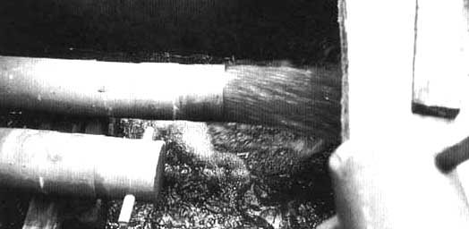
Photo 9 Hydraulic Cleaning of
Roughing Filter (Note the Simple Design of the Fast Opening Device as also
illustrated in Fig. 34, p. IX-9)
|
Exciting Natural Science Lectures
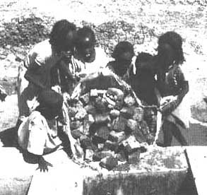
Exciting Natural Science
Lectures
Mr. Augustine is a secondary school teacher in Rehana, a
district centre in a Sahelian region. His favourite subject is natural science
as this subject provides the students with a good base for their adult life.
However, he was often faced with a passive audience, the pupils also had
difficulties in applying the subject taught. For instance, since temperature is
of paramount importance in this hot country, Mr Augustine explained that water
freezes at 0 °Celsius ( °C) or at 32 °Fahrenheit ( °F). The
ambient temperature was around 32 °C which equals about 90 °F, but the
water starts to boil at 90 °C or at 90 °F ? The pupils were confused
about all the listed figures and could not get familiar with the presented
theory as Mr Augustine had no thermometer to make practical
measurements.
However, natural science also had its good sides,
especially when the school children could clean the gravel and the sand of the
community water treatment plant. It was always very shrilling to listen to Mr
Dickson's explanations. Mr Dickson was the caretaker of the treatment plant and
probably an excellent engineer as he knew a lot about his filters. Mr
Augustine's class was invited twice a year to come and clean the filters of the
treatment plant. The school children firstly carried out the manual work lasting
for about two hours. Thereafter, they could sit under the shade of a palm tree
and listen to the exciting stories of Mr Dickson. He told them that very small
living particles are found in the turbid raw water, particles which caused
diseases such as diarrhoea or the terrifying guinea worm. However, when the
water travelled through the filters, these particles, which were retained by the
gravel and the sand, started to starve in the filters due to lack of food and
eventually died. That was also the reason why filter cleaning was not at all a
risky job. The students were able to understand the excellent explanations of Mr
Dickson.
Once Mr Dickson showed the students round papers covered
with small dots. He had received these papers from the laboratory technician who
had recently been examining the raw and treated water for bacteria as he termed
these living organisms. The raw water papers were filled with innumerable yellow
dots whereas the treated water papers had just two dots, one was even red. The
school children were then really persuaded that the filters were an efficient
barrier to safeguarding their health from diseases.
The temperature was sky-high and the sun was beating down
mercilessly on the students who had to return to their lessons. On the way back
to school the debate on bacteria continued and the pupils from the neighbouring
communities discussed the idea of introducing a similar treatment system in
their villages. |
15. Economic aspects
Since numerous factors affect water treatment plant costs,
general, absolute values cannot be cited. Such factors include type of
treatment plant, local material and labour costs, mode of implementation
(construction by private contractors, national institution, or community
participation in a self-help project), and geographic location (affecting type
of structure used to fulfil climatic conditions, accessibility influencing
transport costs, etc.). The overall costs comprise the initial or
construction costs, as well as operating and maintenance costs. The different
costs can be subdivided into local and foreign costs, an aspect of great
importance for developing countries which may have to import part of the
equipment and material required for the treatment
plant.
15.1 Construction costs
An evaluation of the construction cost structure for
different roughing filter projects whose design capacity ranged from 70 to
750 m³/d and located in Tanzania, Kenya, Indonesia, and Australia, reveal
the following, rather similar breakdown of construction costs:
Percentage of the construction costs:
|
- earthwork and structure |
about 70% |
|
- filter medium |
about 20% |
|
- piping and accessories |
about 10% |
Topography and soil conditions (required excavation work and
type of foundation), including type of structure (reinforced concrete or
brickwork), are cost decisive factors for earthwork and structure. Availability
of local filter material in the required sizes significantly influences the
purchase price; i.e., the supply. These first two cost components only have low
economies of scale, however, the relative costs for piping and accessories will
decrease with increasing plant size.
The specific roughing filter construction costs per m³
of installed filter volume range between US $ 100 and 175, except for the
plant in Australia where the specific costs amount to US $ 600. It is, however,
not only the smallest in capacity and built in reinforced concrete, but it also
reflects the prices of a private contractor in an industrialised country. In
developing countries, specific costs ranging from US $ 150 to 200/m³ will
most probably cover the roughing filter construction costs. In self-help
projects where only building material has to be paid for, construction costs can
be reduced by 30-50%.
The specific roughing filter construction costs per m³/d
water output are dependent on filter length and applied filtration rate. For
an assumed total filter length of 5 m and a filtration rate VF of 0.5
m/h for 24 in/d, the resulting specific daily costs amount to:
|
about US $/ m³/ d |
|
construction costs |
60-80 |
|
material costs only
(e.g. in self-help projects) |
30-40 |
Construction costs for slow sand filters are dependent on
the respective filter layout and design. Costs are greatly influenced by
type of filter box chosen (earthen basin and reinforced concrete filter box are
the two extremes), and by the sand price. A slow sand filtration cost study made
in India [59] and based on 1979 prices revealed specific construction costs of
about US $ 25-40/m³/d fore daily design capacity ranging from 70 to 750
m³. A material cost estimate in the Slow Sand Filter Manual [60] revealed
higher specific costs. For the less expensive slow sand filter options with
sloping walls or masonry structure, the material costs were estimated between US
$ 4060/m³/d and US $ 160-240/m³/d respectively. However, the cost
estimate for these plants, whose design capacity ranges between 70 and 350
m³/d, also includes material costs for small clear water tanks of 20 to 40
m³ volume. Owing to the different material and labour costs, it is
difficult to obtain a generally valid cost indication as demonstrated by the two
studies.
A more comprehensive costs evaluation was made of 15 slow
sand filters constructed in the US [17]. Of these 15 plants, five slow sand
filter schemes, ranging in capacity between 130 and 189,220 m³/d, are
gravity operated and have no electrical equipment. A construction cost
evaluation of these five plants resulted in the following subdivision of
construction costs:
Percentage of the construction costs:
|
site work |
about 10% |
|
filter media and gravel |
about 25% |
|
pipes, valves and meters |
about 20% |
|
filter box about |
45% |
The specific construction costs for uncovered slow sand filters
in the US showed the following clear economies of scale:
C = 9,120´A0.49 (R=0.88)
C = construction
costs in US $
A = filter surface area in m²
R = regression value
A slow sand filter plant with a 50 m² filter area, operated
at a 0.15 m/h filtration rate, has a capacity of 180 m³/d. Construction of
such a plant would cost about US $ 62,000. Based on the above equation,
investment costs for a slow sand filter plant with double the filter area and
daily capacity would amount to about US $ 87,000. For slow sand filters,
this results in the following specific construction costs per daily
capacity:
for a slow sand filter plant of:
|
180 m³/d about |
US $ 345/m³/d |
|
360 m³/d about |
US $ 242/m³/d |
These specific costs clearly demonstrate the economies of scale.
Furthermore, when applied to the considered filtration rates in roughing and
slow sand filters (0.5 and 0.15 m/h), the specific construction costs have a
similar order of magnitude. The modified specific costs in the ratio of 0.5/0.15
for slow sand filters would amount to about US $ 100 and 70/m³/d for the
180 and for the 360 m³/d plant, and can be compared to the costs of US $ 60
- 80/m³/d given for roughing filters.
A construction cost comparison is drawn between slow sand
filters and rapid sand filters [18]. According to an evaluation of the specific
construction costs for seven slow sand filter plants, they range between about
US $ 350 and 2,500/m³/d. However, it appears that the construction costs
for small capacity slow sand filter plants are substantially lower than for
equivalent rapid sand filter plants on account of their simple design and
minimum mechanical equipment requirement. In addition, roughing and slow sand
filter plants tend to a have long service life which reduces the annual
depreciation rates of the capital
costs.
15.2 Operating and maintenance costs
Filter cleaning costs are the main operating costs for
roughing and slow sand filters as the filters do not require any chemicals.
On the one hand, since hydraulic roughing filter cleaning is cheap, as the
work can be carried out by the caretaker, the running costs will remain low.
On the other hand, hydraulic filter cleaning is very cost effective with
respect to total operating costs as it reduces the frequency of manual
cleaning known to be labour and cost intensive and generally requiring
additional manpower. The manual cleaning frequency differs for each filter type.
Intake filters are usually cleaned once a week, dynamic filters after every
heavy rainfall. Manual cleaning of roughing filters may be required every three
to five years, or may not be necessary with the installation of an efficient
drainage system. Finally, a slow sand filter run may last from one to six
months.
Since salaries of water plant operators vary significantly,
the time required for filter cleaning is the best way to assess its costs.
Manual cleaning of a 2-m² large intake or dynamic filter may take about
half an hour if the gravel does not have to be removed from the filter box.
Manual cleaning of roughing filter media is more time-consuming as the gravel
has to be removed from the filter box, transported to the washing place, washed
and reinstalled into the filter box. As a rule, about 1.5 m³ gravel per
man/day can be cleaned. Hence, upflow roughing filters run at 0.5 m/h filtration
rate for a 240 m³/d capacity treatment plant will require a total labour
input of about 14 man/days for manual cleaning or, more practically, three men
could clean 20 m³ of gravel in one week. Finally, a man's daily ability to
scrape a 2.5-cm thick layer from a slow sand filter and to transport the sand in
buckets to the sand washing place may be in the order of 100 m² filter
area. 50 m² slow sand filter area (filtration rate 0.20 m/h) would be
required for the 240 m³/d treatment plant, or half a day for one man. More
realistically, two men would be able to scrape the sand from a 240 m³/d
slow sand filter plant in half a day. Sand washing can be carried out later when
the slow sand filters have restarted operation. However, a 240 m³/d plant
capacity is split into several roughing and slow sand filter units, the
different filters are cleaned successively in order to guarantee an
uninterrupted supply of water. These specific cleaning capacities and the
annual cleaning time required for the operation of 240 m³/d treatment plant
are summarised in Table 8.
Table 8 Annual Cleaning Time for a 240 m³/d Treatment
Plant
|
Treatment Scheme |
intake filter |
uppflow roughing filter |
slow sand filter |
|
Treatment Design |
|
·filtration rate vF
|
1.25 m/h |
0.5 m/h |
0.20 m/h |
|
· filter bed area A |
8 m² |
20 m² |
50 m³ |
|
· filter bed height H |
0.4 m |
1 m |
1 m |
|
· filter material volume V |
3.2 m³ |
20 m³ |
50 m³ |
|
· filter units - |
2 |
2 |
2 |
|
· filter area per unit |
4 m² |
10 m² |
25 m² |
|
Cleaning Interval |
|
· dry season 8 months |
2 x/month |
1 x/month |
1 x/4 months |
|
· rainy season 4 months |
4 x/month |
2 x/month |
1 x/4 months |
|
Cleaning Time per Filter |
|
· hydraulic cleaning |
- |
0.25 man hour |
|
|
· manual cleaning |
0.5 man hour |
|
8 man hours |
|
Cleaning Time |
|
· dry season |
16 man hours |
4 man hours |
32 man hours |
|
· rainy season |
16 man hours |
4 man hours |
16 man hours |
|
Annual Cleaning Time |
32 man hours |
8 man hours |
48 man hours |
|
Manual Filter Cleaning |
|
· frequency of manual filter
material washing |
1 x/year |
1 x/5 years |
1 x/10 years |
|
· cleaning capacity |
1.5 m³/man/day |
1.5 m³/man/day |
1 m³/man/day |
|
· cleaning time per filter 1
man/day |
7 man/days |
25 man/days |
|
|
· contribution to annual
cleaning time |
16 man hours |
22 man hours |
40 man hours |
|
Total Annual Cleaning Time |
48 man hours |
30 man hours |
88 man hours |
Since operation of roughing and slow sand filters only
requires labour input, any community with a strong interest in treated water
can afford the use of such filters. The running costs can be reduced to a
minimum if the community participates in filter cleaning. However, routine
operation and maintenance of a treatment plant will be carried out by a
caretaker or operator who significantly influences efficiency, reliability and
water treatment costs. The community should appreciate his work and reward him
accordingly. The fully self-reliant treatment processes are therefore not
dependent on any external financial and technical support. Important
operating and maintenance costs, which are often too high for a rural community,
can be reduced to an absolute minimum by the installation of self-reliant
treatment processes, such as roughing and slow sand filtration. This is one
criteria for long-term operation of any water supply
scheme.
15.3 Overall costs of water supply schemes
The construction costs of a water treatment plant may make up
an important part of the overall investment costs of a water supply scheme.
Cost comparisons between different water supply alternatives should
therefore be made in the preliminary project design phase.
Selection of the water source should be based on technical
and economic considerations. Operating and maintenance costs of a
gravity-operated system are low compared to a slow sand filter plant, which
requires about 40% of the initial construction costs to operate a plant for a
period of 20 years. Under such aspects, it may be more economical to tap a more
remote source of good quality water and invest in a longer water supply main
than in a treatment plant.
Construction costs for rural water supply schemes can be
subdivided as follows:
Percentage of the construction costs:
|
- intake works |
5 - 25% |
|
- treatment plant |
15 - 30% |
|
- distribution system |
50-70% |
Annual operating and maintenance costs have to be added to
the annual capital recovery costs to obtain a correct cost analysis.
However, since operating and maintenance costs greatly differ, a general
estimate is difficult. 2% of the construction costs may be an indicative figure
to estimate operating and maintenance costs of roughing and slow sand filters,
excluding the depreciation costs for the treatment plant.
Finally, the local and foreign currency cost component can
also be an important factor in project budgeting. Roughing and slow sand
filters are an essentially self-reliant technology which is largely reproducible
with local means. Based on the construction cost structure, 80 - 90% of the
investment costs are expenditures for construction material, such as gravel,
sand, cement, bricks and stones, and for labour, both readily available in the
country. The remaining 10 20% are costs for the purchase of pipes, valves and
accessories (V-notch weirs, gauging rods) which may partly have to be imported.
Hence, roughing and slow sand filters make maximum use of local resources,
require mostly local currency and reduce the need for foreign currency.
|
Padlocks Enhanced Collection of Water Fees
The tribe of the Ewes in West Africa is known for its
strong communal spirit and leadership. These attributes also formed the basis
for the successful water supply project implemented as self-help project six
years ago. The population had been suffering from bilharzia and guinea worm
which had spread over the village through ponds used both as water source by the
villagers and as breeding place by the two tropical diseases. The community
decided to improve its water supply during the annual assembly held at Easter.
Kolly, one of their citizens who had been trained abroad in civil engineering,
designed the water supply scheme. It consisted of roughing and slow sand filters
fed by gravity from the largest lagoon, a pumping station, a reservoir located
on top of the central hill, and a distribution system supplying the nine
community settlements of 3,500 inhabitants.
The community, which contributed in cash and kind to the
project, could cover half of the total costs of the project which was completed
in three years of hard communal labour. Leadership was not always easy during
this period as technical problems had to be solved and the community motivated
to work. However, the last tap on the most remote public standpost was finally
installed and the electric pumps connected to the grist system. At that moment,
water should have started to flow but it did not. Since some of the settlements
had not yet paid their fees to the water committee, operation of the water
supply was put off until all due payments had been made. The community went
through a rough period, however, when the last Cedi was finally paid to "Mister
Money", the nicknamed treasurer of the project, an important celebration was
organised by the entire community to inaugurate the new water supply
scheme.
Public standposts located in every settlement
significantly reduced the walking distance to the water sources. Most
inhabitants enjoyed the commodity, however, some citizens wanted to know why
they still had to pay for water although they had extensively contributed to the
project. The water committee fixed the monthly water rate for each adult at 500
Cedis, the equivalent price of a bottle of beer. However, the electricity bill,
the salary of the two caretakers and minor maintenance costs had to be covered
by the water fees levied separately in each settlement.. Despite lengthy
meetings with the water committee, a few villagers were still not willing to pay
the fixed rate. This gave rise to tariff policy disputes and jeopardised smooth
operation of the water supply scheme until the local blacksmith suggested the
installation of padlocks with steer cylinders on the taps. All the taps were
thus equipped with padlocks which allowed a controlled supply of water to all
those who settled their water bill regularly.
Today the opponents of the water fees are no longer
contesting them, and the padlocks installed at the public standposts hinder
people from neighbouring villages trying to collect water illegally.
|
16. Design examples
Five design examples are presented hereafter to illustrate
prefilter and roughing filter application. The population of rural
communities is often in the range of 500 to 5,000 inhabitants. The daily water
demand is dependent on the service level; i.e., whether the population is
supplied by public standposts, yard or house connections, as well as on the
water price and water rate system used; i.e., flat rate or billed on the basis
of water meter readings. In water supply schemes with public standposts, daily
water demands can vary between 20 and 30 litres per person.
The following design examples are based on the supply of a
village with a current population of about 1,500 inhabitants and annual growth
rate of 3 %. The current water supply through public standposts amounts to 20
litres of water per inhabitant. However, water supply installations have to be
dimensioned to meet future water demands of the design population. For a
10-year design period, a treatment plant operated on a 24 hour basis will
require the following design capacity:
|
· current population |
1,500 inhabitants |
|
population in ten years |
(1+0.03)10 ´ 1,500 = 2,000 inhabitants |
|
· current specific water demand
|
20 l/p/d |
|
specific water demand in 10 yrs |
30 l/p/d |
|
· current daily water demand
|
1,500 ´ 20 = 30 m³/d |
|
daily water demand in 10 yrs |
2,000 ´ 30= 60 m³/d |
Type of raw water source and raw water quality determine
extent and type of treatment. Turbidity level and respective peak values are
the most important parameters for pretreatment unit design. Raw water quality
data are often scarce and records of peak values generally unavailable. With
time, raw water sources may deteriorate in quality and quantity. Watershed
protection is therefore essential for a long-term use of the source. However,
such projects may not prevent water quality deterioration and, therefore, the
treatment plant layout should allow for the integration of additional
pretreatment steps if these turn out to be necessary in the future. Fig. 53
illustrates possible annual raw water quality variations for the following
design examples presented
hereafter.
16.1. Treatment of an upland river
Our presumed village is located in a hilly area of a West
African country. The area is very rural and scarcely populated. Temperature and
climate are pleasant, with cold nights and annual rainfall of about 2,000 mm,
ideal for tea and coffee growth. A small upland river flows through tea and
coffee plantations located on gently sloping hills surrounded by dense forests.
In future, the farms will be expanding their plots further uphill. The
central government has recently granted construction of a road into the
catchment area to facilitate the exploitation of wood. A water supply is
foreseen to compensate the villagers for the now polluted small upland river.
After a sanitary inspection of the catchment area, as well as a
discussion with the village chief and with a recently established water
committee, it was decided to construct slow sand filters according to the
respective graph shown in Fig. 54. However, the slow sand filters have to be
protected from high silt loads carried by the river during the short but heavy
rainfalls. The algorithm discussed and presented in Fig. 43 of Chapter 12
and attached in Annex 6 is used to determine the type of pretreatment required.
Fig. 54 shows that the planned slow sand filters are at present sufficiently
protected by dynamic filters, however, intake filters may be required in future
if the raw water quality deteriorates due to over exploitation of the
catchment area.
Please note that Figs. 54 - 57 are duplicates of Fig. 43 shown
on page XII-4 to facilitate its use.

Fig. 53 Annual Turbidity Variation of
Different Surface Water Sources
The different filter units for the treatment of an upland
river water are dimensioned as follows:
|
· treatment plant
capacity |
60 m³/d |
|
60:24= 2.5 m³/h |
|
· dynamic filter |
|
filtration rate |
5 m/h |
|
total filter area required |
2.5 m/h: 5 m/h = 0.5 m² |
|
number of filter units |
1 |
|
· slow sand filters |
|
filtration rate |
0.125 m² |
|
total filter area required |
20 m² |
|
number of filter units |
2 |
|
filter area per unit |
10 m² |
|
· Intake filter |
|
(foreseen in case of future water quality deterioration) |
|
filtration rate |
1 m/h |
|
total filter area required |
2.5 m² |
|
number of filter units |
1 |
A possible dynamic filter layout is illustrated in Annex 6/1 and
general design guidelines are summarised in Fig. 37 of Chapter 10. Layout and
design of slow sand filters are described in Annex
3.
16.2 Treatment of a lowland stream
The village in question may be situated in a valley of the
Latin-American Andes. At that high altitude, grass and farmland may predominate
and forests are scarce. The living condition of the population is difficult and
the farmers are forced to use every possible plot of fertile land as a means of
subsidence and for cash crops. The only perennial water source and water
supply of the population is the valley river loaded with lateritic soil eroded
into the stream. The yield of the few springs generally emerging at the
bottom of the hills is low and the springs dry up in the hot season. Groundwater
is non-existent in the valley.
The river and its small waterfalls upstream fortunately allow
construction of a gravity water supply scheme. However, the river is
considerably polluted by the villages located in the upper part of the valley.
The Junta Administrativa, a village committee also responsible for community
water supply, is aware of this public health risk and has initiated a water
supply project with the support of a non-governmental organisation. Based on the
selection criteria illustrated in Fig. 55, the project team has designed a
water treatment scheme consisting of intake filters, horizontal-flow roughing
filters and slow sand filters. Up flow roughing filters in series are an
economic alternative to horizontal-flow roughing filters, and their hydraulic
cleaning is also easier than the proposed option.
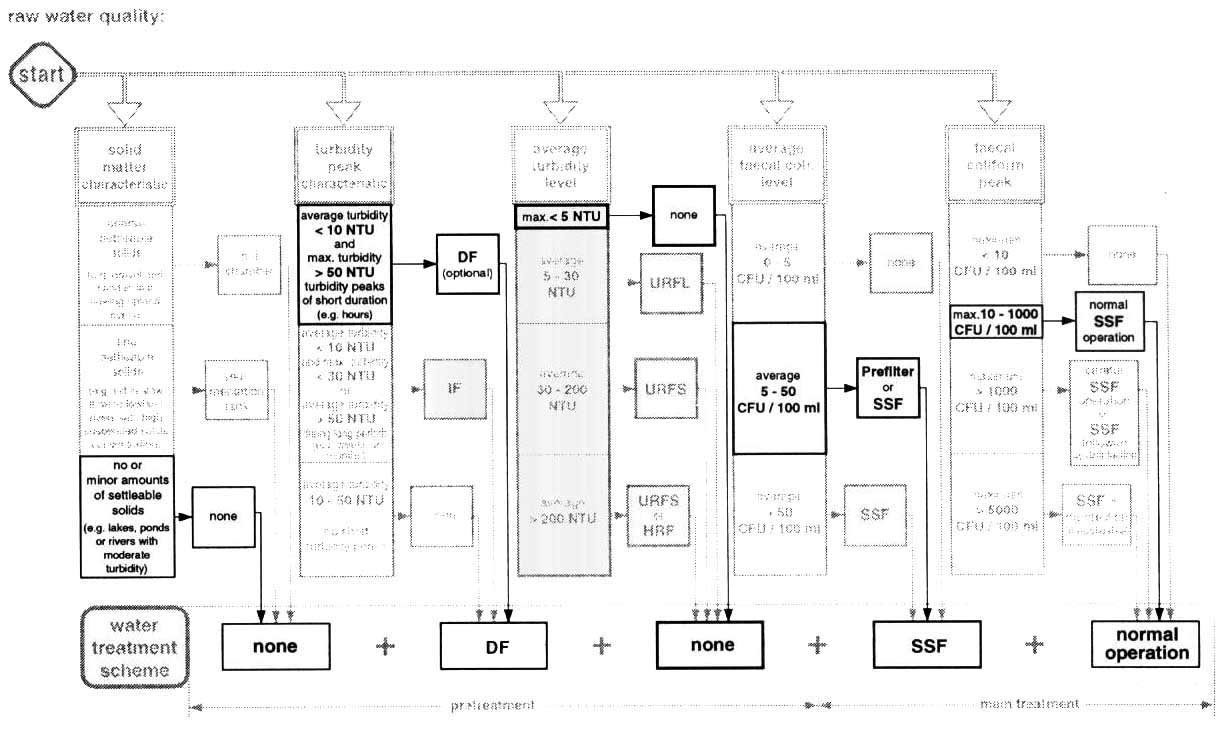
Fig. 54 Treatment option for an
Upland River
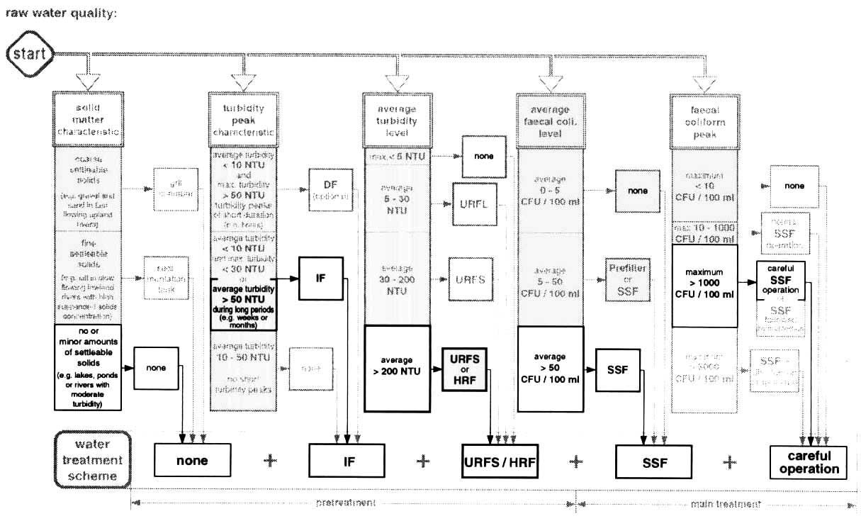
Fig. 55 Treatment Option for a
Lowland Stream
The different filter units for the treatment of a lowland
river water are dimensioned as follows:
|
· treatment plant capacity |
60 m³/d |
|
60:24 = |
2.5 m³/h |
|
· intake filters |
|
filtration rate |
0.8 m/h |
|
total filter area required |
3.2 m² |
|
number of filter units |
2 |
|
filter area per unit |
1.6 m² |
|
· horizontal-flow roughing
filters |
|
filtration rate |
0.5 m/h |
|
total filter area required |
5 m² |
|
number of filter units |
2 |
|
filter area per unit |
2.5 m² |
|
layout of filter bed |
|
1st gravel fraction F 12 -18 mm |
3.5 m |
|
2nd gravel fraction F 8 - 12 mm |
2.5 m |
|
3rd gravel fraction F 4 - 8 mm |
1 m |
|
· slow sand filters |
|
filtration rate |
0.125 m/h |
|
total filter area required |
20 m² |
|
number of filter units |
2 |
|
filter area per unit |
10 m² |
|
· upflow roughing filters in
series |
|
(as an alternative to horizontal-flow roughing filters) |
|
filtration rate |
0.4 m/h |
|
total filter area required |
6.25 m² |
|
number of filter units |
3 |
|
filter area per unit |
6.25 m² |
|
layout of filter bed |
|
1st filter unit F 12 -18 mm |
1 m |
|
2nd filter unit F 8 - 12 mm |
1 m |
|
3rd filter unit F 4 - 8 mm |
1 m |
A possible layout of the intake filters is illustrated in Annex
6/2, and the general design guidelines are summarised in Fig. 37 of Chapter 10.
A design example for horizontal-flow roughing filters is attached to Annex 6/3,
and the respective design guidelines are listed in Fig. 39. Layout and design of
upflow roughing filters are described in Annex 6/ 4 and Fig. 38, and those of
slow sand filters in Annex
3.
16.3 Treatment of reservoir water
The village may be located in Asia. The landscape there may be
very flat and interlaced by many canals regulating the water table essential for
the cultivation of rice. Land is very scarce and, therefore, even the smallest
plots are used for agriculture. Nevertheless, some larger lagoons for duck
farming can also be spotted. In former times, the population used the canal
water as raw water source, however, this source has become increasingly polluted
due to increased motorisation of the ships and to industrial wastewater
discharge. Hence, the lagoons although exposed to pollution from aquaculture
and agriculture - are qualitatively the best raw water source nowadays.
Groundwater may in the long run not be used as water source due to the
progressing infiltration of sea water which gradually increases water salinity.
To avoid constructing a water supply scheme with two pumping
stages, the water treatment plant will have to be located at the lowest point
next to the dam of a lagoon. The treatment plant will have to be gravity-fed,
which will ensure its continuous operation. Ducks and human activities around
the lagoon deteriorate/he microbiological water quality. Furthermore, use of
agricultural fertilisers enhances eutrophication of this reservoir water. A
treatment scheme, as illustrated in Fig. 56, is therefore necessary to turn the
raw water into drinking water. The population's high drinking water standards
will not allow the supply of chlorinated water as it affects the taste of tea.
It was, therefore, decided to construct a treatment scheme applying
natural purification processes such as upflow roughing filters in layers and
slow sand filters. A construction brigade started constructing the treatment
plant which was commissioned six months later. This short construction period
was possible only thanks to the availability of local material.
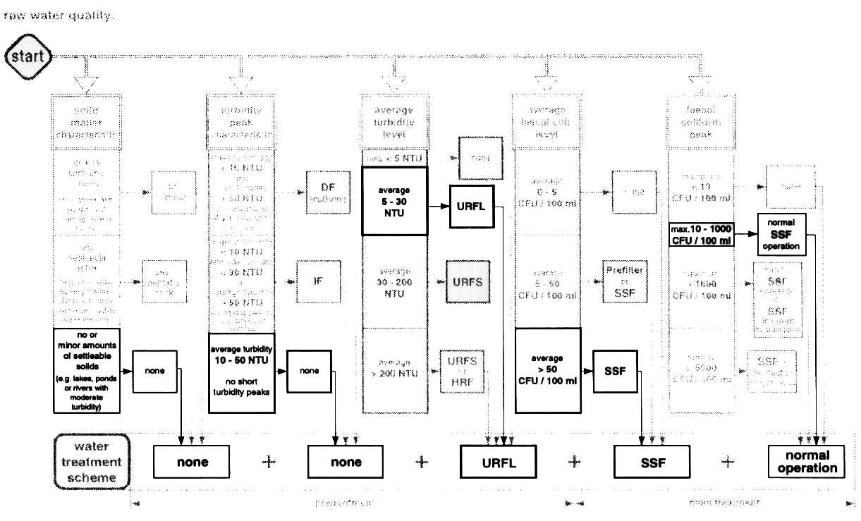
Fig. 56 Treatment option for a
Reservoir Water
The different filter units for the treatment of a reservoir
water are dimensioned as follows:
|
· treatment plant
capacity |
60 m³/d |
|
60 : 24 = 2.5 m³/d |
|
|
· upflow roughing filters in
layers |
|
filtration rate |
0.3 m/h |
|
total filter area required |
8.33 m² |
|
number of filter units |
2 |
|
filter area per unit |
4.2 m² |
|
layout of filters bed |
|
|
1st gravel fraction F 8 - 12 mm |
0.4 m |
|
2nd gravel fraction F 6 - 10 mm |
0.3 m |
|
3rd gravel fraction F 2 - 6 mm |
0.3 m |
|
· slow sand filters |
|
filtration rate |
0.125 m/h |
|
total filter area required |
20 m² |
|
number of filter units |
2 |
|
filter area per unit |
10 m² |
An example of a layout of an upflow roughing filter in layers is
illustrated in Annex 6/4, and general design guidelines are summarised in Fig.
38 of Chapter 10. Layout and design of slow sand filters are described in Annex
3.
16.4 Rehabilitation of a slow sand filter plant
Finally, the village in question may have completed its
community water supply 25 years ago. However, the situation in this West African
country has changed in the meantime. The population has increased, however, most
of its young people have left the village for town. Their income, earned in the
commercial capital, allows them to construct stately houses which they use
during weekends and after retirement, and to support the infrastructural
projects in the village. Inflation and a drop in prices for agricultural
products forces the rural population to practice extensive land farming. Feeder
roads are constructed to improve transport capacity to the capital and export to
foreign countries. Indigenous forests are cut down and tropical wood exported.
The sturdy structures of the water supply allows a more or less regular water
supply to the village.
However, the distributed water quality has deteriorated
significantly in the last ten years and has given rise to consumer complaints.
The existing sedimentation tanks and slow sand filters can no longer cope with
the increased raw water turbidity.
The small upland river, which was well-protected by a dense
forest in former times, is now exposed to numerous sources of pollution.
Extensive and careless farming has enhanced soil erosion, cows in the grassland
have considerably increased in numbers and neighbouring villagers have started
farming in the catchment area. As shown in Fig. 53, river water turbidity has
increased noticeably and springs are now running dry in the hot season. Slow
sand filter runs amount to a few weeks in the dry season and are reduced to a
few days in the rainy season. The sand has therefore been removed from the
filter boxes and the water now flows unfiltered into the reservoir. As the
sedimentation tanks cannot cope with the increased turbidity, they will have to
be converted into roughing filters to allow a reasonable slow sand filtration.
However, the vault-type sedimentation tanks are not easily converted into
roughing filters. In such situations, part of the slow sand filter area may be
used for the installation of upflow roughing filters. The capacity loss of the
reduced slow sand filter area can be compensated by higher filtration rates of
adequately pretreated raw water.
A rehabilitation option for an overloaded slow sand filter plant
is illustrated in Fig. 57.
An example of a possible layout of an upflow roughing filter in
layers is illustrated in Annex 6/4, and general design guidelines are summarised
in Fig. 38 of Chapter 10. The Integration of an upflow roughing filter into a
sedimentation tank or into a slow sand filter is illustrated schematically in
Annex 615.
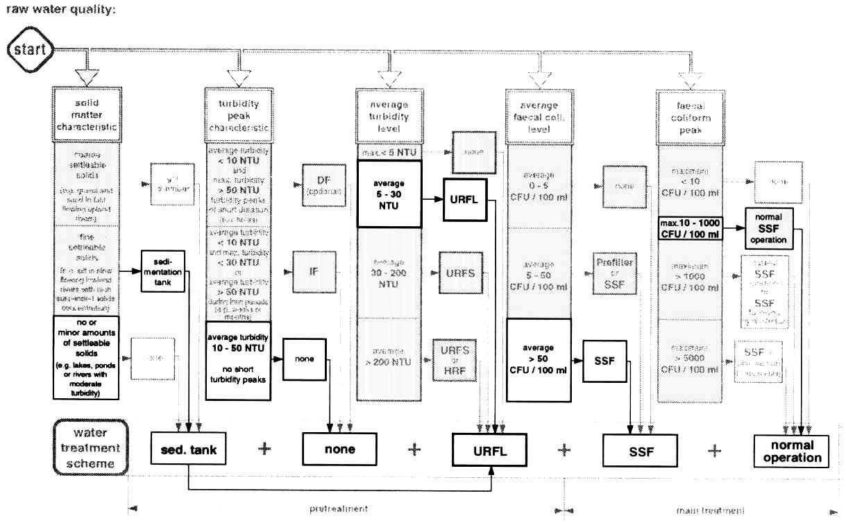
Fig. 57 Rehabilitation option for a
Slow Sand Filter Plant
The rehabilitated treatment plant is dimensioned as
follows:
|
· original treatment plant
capacity |
|
60 |
m³/d |
|
60: 24 = |
2.5 |
m³/h |
|
· existing sedimentation
tank |
|
length |
4 |
m |
|
width |
1.5 |
m |
|
depth |
1.7 |
m |
|
tank volume |
10 |
m³ |
|
number of units |
1 |
|
|
surface load |
0.4 |
m/h |
|
retention time |
4 |
hours |
|
· existing slow sand
filters |
|
filter length |
5 |
m |
|
filter width |
2 |
m |
|
filter area |
10 |
m² |
|
number of units |
2 |
|
|
filtration rate |
0.125 |
m/h |
|
rehabilitation of the treatment plant |
|
· new treatment plans
capacity |
|
90 |
m³/d |
|
90: 24= |
3.75 |
m³/h |
|
1st option: |
|
· transformation of the
sedimentation tank into two upflow roughing filter units |
|
· upflow roughing filters in
layers |
|
total filter area required |
|
6 |
m² |
|
number of filter units |
|
2 |
|
|
filter area per unit |
|
3 |
m² |
|
filtration rate |
|
0.6 |
m/h |
|
layout of filter bed |
|
|
|
|
1st gravel fraction F 12 - 18 mm |
0.7 |
m |
|
2nd gravel fraction F 8 - 12 mm |
0.4 |
m |
|
3rd gravel fraction F 4 - 8 mm |
0.4 |
m |
|
· slow sand filters |
|
total filter area required |
|
20 |
m² |
|
number of filter units |
|
2 |
|
|
filter area per unit |
|
10 |
m² |
|
filtration rate |
|
0.19 |
m/h |
|
2nd option: |
|
transformation of part of the slow sand filters into upflow
roughing filters |
|
· existing sedimentation
tank |
|
new surface load |
|
0.6 |
m/h |
|
new retention time |
|
2.7 |
hours |
|
· upflow roughing filter
|
|
integrated into slow sand filter box |
|
filter length |
|
1.25 |
m |
|
filter width |
|
2 |
m |
|
filter area |
|
2.5 |
m² |
|
number of units |
|
2 |
|
|
total filter area |
|
5 |
m² |
|
filtration rate |
|
0.75 |
m/h |
|
layout of filter bed |
|
1st gravel fraction F 12 - 18 mm |
0.7 |
m |
|
2nd gravel fraction F 8 - 12 mm |
0.4 |
m |
|
3rd gravel fraction F 4 - 8 mm |
0.4 |
m |
|
· reduced slow sand
filters |
|
available filter length |
|
3.75 |
m |
|
available filter width |
|
2 |
m |
|
filter area per unit |
|
7.5 |
m² |
|
number of filter units |
|
2 |
|
|
total filter area |
|
15 |
m² |
|
new filtration rate |
|
0.25 |
m/h |
16.5 Standard designs for compact water treatment plants
Water treatment plant projects can be implemented on a standard
design basis to reduce design inputs as well as construction time and costs.
This approach is especially appropriate in rural water supply programmes for the
construction of several treatment plants having to treat raw water of similar
quality. In such situations, routine construction procedures can be developed
to reduce construction periods. Furthermore, compact designs and careful
supervision of the construction will lower investment costs and enable the use
of economic construction procedures such as the ferrocement technique.
Standard design modules often cover a range of different design capacities.
They may be implemented successively in different construction phases to meet
the actual water demand of the community. Every water treatment project will
nevertheless have to be carefully adapted to the local situation and, therefore,
calls for a critical evaluation of the prevailing conditions.
A standard design example is illustrated in Annex 6/6 . Upflow
roughing filter(s), slow sand filter(s) and a reservoir are integrated in one
structure. This example uses a circular design, often applied in reservoir
construction, and takes advantage of locally available construction techniques.
A circular ring, placed around the reservoir located in the centre, provides
space for two treatment lines comprising upflow roughing filters and slow sand
filters. Design capacity of the illustrated example amounts to 30 m³/d.
Hence, two such standard design units are required to cover the water demand of
the village in question. These two units may be located in different places to
treat different raw water sources, and may improve the reliability of a water
supply system. Depending on the raw water quality, the illustrated structure
could be used to host alternative treatment systems such as upflow roughing
filters installed in the outer ring and two slow sand filters placed in the
centre tank. Such a layout would require a separate reservoir.
The construction of small standard design units also enables
a phased increase of the treatment plant design capacity, satisfying the
future water demand development. A further advantage of a phased implementation
is the integration of the operational experience in the extension design.
Filters can frequently be operated at higher filtration rates without
affecting the treated water quality or without substantially reducing filter
running periods. The filtration rate of slow sand filters may for instance be
increased from 0.1 to 0.2 m/h (recommended range in the literature). With an
efficient pretreatment and use of sand coarser than 0.15 - 0.35 mm (recommended
range in the literature for the specific sand size d10%), it may be increased to
0.3 and exceptionally to 0.4 m/h.
The filter units of a compact water treatment plant are
dimensioned as follows:
|
· treatment plant capacity |
30 |
m³/d |
|
30 . 24= |
1.25 |
m³/h |
|
· upflow roughing filters in
layers |
|
|
|
filtration rate |
0.3 |
m/h |
|
total filter area required |
4.2 |
m² |
|
· slow sand filters |
|
|
|
filtration rate |
0.125 |
m/h |
|
total filter area required |
10 |
m² |
17. Final remarks
If you have reached this part of the manual, you are either an
experienced reader who first consults the executive summary and conclusions of a
publication, or a person with a real interest in the roughing filter technology.
After having given enough evidence in favour of prefilters and roughing filters,
this manual will conclude with some strong statements on rural water supplies
in developing countries, and will emphasise some weak aspects pertaining to
the implementation of water treatment plants.
1. No water source will reach people who merely read
publications. Therefore, since this manual presents a practical technology
for field application, it is not just meant for mental pleasure nor to be filed
away in a bookshelf, the reader is kindly requested to take action in his
field by promoting and implementing appropriate technologies.
2. Appropriate means adapted to the local condition. Therefore,
no technology can be universally appropriate. This is also true for slow
sand filtration. The often negative experience with this treatment process is
frequently the result of an inappropriate raw water quality.
3. Application of similar technological levels is a critical
factor to achieve a sustainable system. Insufficiently flocculated and
settled water pretreated by complex and unstable processes will create
operational difficulties even for the simple and sturdy slow sand filters. Raw
water conditioned by prefilters and roughing filters will usually meet slow sand
filter requirements.
4. Actual demand and economic aspects are decisive
factors for the selection of a water supply system. Prefilters, roughing filters
and slow sand filters are fascinating treatment combinations as they are based
on a reliable, sustainable and reproducible technology. However, since these
filters require a considerable structural input, they should only be favoured if
no superior water quality source is available and if water treatment is truly
necessary.
5. This manual is mainly a technical document. However, water
supplies can be compared to computers as they both depend on hardware and
software. The water supply users have to decide, contribute and operate
these facilities. Sociocultural aspects must be integrated in a project, and
institutional aspects considered carefully. Degree of training, support and
assistance to caretakers greatly influences the performance and lifetime of a
water supply. Hence, an appropriate and sustainable technology always requires
an interdisciplinary input as illustrated in Fig. 58.

Fig. 58 Multidisciplinary Inputs for
Appropriate and Sustainable Technologies
6. Information exchange should be reciprocal. Your
experience with roughing and slow sand filters is important and your feedback
essential. SANDEC, therefore, hopes to receive your views on this manual,
especially your practical experience with the presented filter technology.
Provision of safe water is a great challenge. We hope that this
manual is a step in the direction of the following policy formulated in New
Delhi [61 ] at the end of the International Water Supply and Sanitation Decade
"Some for all rather than more for some"
The Expert's Mirror
The villagers of some town somewhere were ready for the
important celebration - the inauguration of their water supply system. Forgotten
were the hardships of the past two years and intensive work of the construction
of their self-help water supply system. All the villagers and the District
Engineer could be proud of having brought safe and clean water in the village.
The District Engineer, who have also supervised construction, trained the
caretakers in operation and maintenance work and had advised the water committee
in bookkeeping, spent the last few days assisting the villagers in completing
their system and organising the commissioning ceremony. Everything was ready in
time for D-day when the "big shots, the water gurus or los sabios", commonly
called experts, honoured the village with their presence. They instantly began
to inspect the work of the villagers, to evaluate the system and to propose
modifications. They also found the small District Engineer and bombarded him
with questions, such as: "what's your role in project etc., etc.". Fortunately
the drummers had started to play and the District Engineer did not have to
answer the question immediately. After the inauguration act, everybody had time
to visit the installations, the intake work, the treatment plant, the
distribution system with the reservoir and the public standposts. The atmosphere
became more relaxed even for the experts, and the small engineer had the
opportunity to explain his role in the projects. They were standing by the
reservoir overlooking the village when he told them that the first listened to
the real needs of the villagers and had to accepted their final decision even if
it meant that they did not want to change their water supply system.
Late afternoon, the District Engineer, tired of the hectic
days, boarded the bus to his home town. One of the experts was also in the bus
and sat next to an crying boy. The engine of the bus was making an terrible
noise. The village was already several miles away but the small boy went on
crying. Embarrassed by his unusual situation, the expert concentrated on reading
his book. The District Engineer then decided to sit next to boy in tears. To his
surprise he discovered that the boy was afraid of the terrible noise of the bus
engine. After a while the boy slowly calmed don and starting talking with to the
District Engineer. The experts, amazed by situation looked out of the window and
only saw his own face reflected by the light of the sunset in the
windowpane.
Most people tent to behave like the expert instead of the
listening, observing and trying to understand the situation before
acting.
References
[1] Baker M.N., The Quest for Pure Water, AWWA, 1948 + 1981
[2] Wagner, E.G., Upgrading Drinking Water Treatment Plants, WHO
Working Group for Operation and
Maintenance, (in press)
[3] Hespanhol I., Investigaci�n Sobre el Comportamiento y
Applicabilidad de los Filtros Lentos en el Brazil, Universidad de S�o Paulo,
Brasil, 1969
[4] Wegelin M., et al, Slow Sand Filter Rehabilitation and New
Treatment Plant Design in Rural Cameroon, Proceeding 3rd International Slow
Sand/Alternative Biofiltration Conference, John Wiley & Sons, 1996
[5] NEERI, Evaluation of Four Slow Sand Filter Plants in Andrah
Pradesh, 1993
[6] Lloyd B., Helmer, R., Surveillance of Drinking Water Quality
in Rural Areas, WHO and UNEP, John Wiley & Sons, 1991
[7] Oxfam/DelAgua Water Testing Kit, OXFAM, Oxford, UK, August
1988
[8] Hutton, L.G., Field Testing of Water in Developing
Countries, WRC, Water Research Centre, Loughborough UK, 1983
[9] De Lange, E., Manual for Simple Water Quality Analysis, IWT
Foundation, Amsterdam, NL, 1994
[10] Wegelin, M., Boller, M., Schertenleib, R., Particle Removal
by Horizontal-flow Roughing Filtration, Journal of Water Supply Research and
Technology - Aqua Vol. 36, pp. 80-90,1987
[11] Collins, M.R., Westersund, C.M., Cole, J.O., Roccaro, J.V.,
Evaluation of Roughing Filtration Design Variables, AWWA Research Foundation and
American Water Works Association, 1994
[12] Pardon, M.O., Treatment of Turbid Surface Water for Small
Community Supplies, Ph. D. Dissertation. Robens Institute, University of Surrey,
Surrey, England, 1989
[13] Del Mundo Jusi, O., Pretreatment Applications of
Horizontal-flow Coarse Media Pre-Filtration, Thesis, AIT, Asian Institute of
Technology, Bangkok, Thailand, April 1987
[14] Boller, M., Filtermechanisms in Roughing Filters, Journal
of Water Supply Research and Technology - Aqua Vol. 42, pp. 174-185,1993
[15] Visscher J.T., Paramasivam R., Raman A., Heijnen H.A. Slow
Sand Filtration for Community Water Supply, IRC, Technical Paper No. 24, June
1987
[16] Hendricks D. (editor) Manual of Design for Slow Sand
Filtration, AWWA Research Foundation, 1991
[17] Logsdon G. S. (editor), Slow Sand Filtration, ASCE Report,
1991
[18] Lambert, S.D., Graham, N.J.D., A Comparative Evaluation of
the Effectiveness of Potable Water Filtration Processes, Journal of Water
Supply, Research and Technology - Aqua Vol. 44, pp. 38-51,1995
[19] Graham, N., Hartung, H., Performance of Slow Sand Filters
in Refugee Water Supplies in Somalia, Waterlines, _,3,p. 19, 1988
[20] Mbwette, T.S.A., Graham, N.J.D., Pilot Plant Evaluation of
Fabric-Protected Slow Sand Filters. In [28]
[21] Schalekamp, M., Slow Sand Filter for Ground-Water Recharge.
Ten Times longer Filter Run Than was Usual up to Now. Indian Water Works
Association Journal, 1992
[22] Barrot L.P., Llloyd B.J., Graham N.J.D. Comperative
evaluation of two novel disinfection methods for small-community water treatment
in developing countries, Journal of Water Supply Research and Technology - Aqua
Vol. 39, pp. 396-404,1990
[23] WHO, Disinfection of Rural and Small-Community Water
Supplies, Water Research Centre, Medmenham, UK, 1989
[24] Solsona, F., Disinfection for Small Water Supplies, Water
Technology, CSIR, Pretoria, South Africa, 1990
[25] Grondin, P.M., Chloration en milieu rural dans les pays en
vole de d�veloppement, Programme Solidarit� Eau, Paris, France, 1996
[26] Jeffery, T.D. et al., Hydraulic Ram Pump: A guide to ram
pump water supply systems, IT Publication, 1992
[27] van Loodsrecht, C.M.C., Lyklema, J., Norde, W. and Zehnder,
A.J.B., Hydrophobic and electrostatic parameters in bacterial adhesion, Aquatic
Science 52, pp. 103-114, 1990
[28] Graham, N.J.D. (Ed.) Slow Sand Filtration, Recent
Developments in Water Treatment Technology, Ellis Horwood Limited, Chichester,
UK, 1988
[29] Collins, M.R., Graham, N.J.D., (Eds.), Slow Sand
Filtration, An International Compilation of Recent Scientific and Operational
Developments, AWWA, American Water Works Association, Denver, CO 80235, USA,
1994
[30] Graham, N.J.D., Collins, M.R. (Eds.), Advances in Slow Sand
and Alternative Biological Filtration, John Wiley & Sons, 1996
[31] Probst, E., Von Besonderheiten in der Wasserversorgung auf
Burgen, Nachrichten Burgenverein 6/1937
[32] Kuntschik, O., Optimization of Surface Water Treatment by a
Special Filtration Technique, Journal of the American Water Works Association,
October 1976
[33] Thanh, N.C., Horizontal-flow Coarse-Material Prefiltration,
Research Report No. 70, AIT, 1977
[34] Monitoring and Evaluation of Village Demonstration Plants,
Technical Report, Project Managing Committee and AIT, October 1981
[35] Perez, J., Modular Plants for Water Treatment, Volumes 1
and 2, CEPIS Technical Documents Series 8,1982
[36] Wegelin, M. and Mbwette, T.S.A., SSF Research Report No. 2,
University of Dar es Salaam, 1980
[37] Wegelin, M. and Mbwette, T.S.A., SSF Research Report No. 3,
University of Dar es Salaam, 1980
[38] Wegelin, M., Boller, M. and Schertenleib, R., Particle
Removal by Horizontal-flow Roughing Filtration, AQUA, Vol. 36, pp. 80-90,1987
[39] Wegelin, M., Horizontal-flow Roughing Filtration: A Design,
Construction and Operation Manual, IRCWD Report No. 6/1986
[40] Wegelin M., Schertenleib R., Boller M. The decade of
roughing filters - Development of a Rural Water treatment Process for Developing
Countries, Journal of Water Supply Research and Technology - Aqua Vol. 40, pp.
304-316,1991
[41] Riti M.M., Horizontal Roughing Filter in Pretreatment of
Slow Sand Filters, Thesis, Tampere University of Technology, 1981
[42] Tilahun G.T., Direct Filtration with Horizontal Roughing
Filter as Pretreatment, Thesis, Tampere University of Technology, 1984
[43] Symonds Ch.N., Aspects of prefiltration concerned with the
application of small scale slow sand filtration in rural communities, University
of Surrey, 1985
[44] Siripatrachai T., Physical and mathematical analysis of the
performance of horizontal roughing filtration, Intemational Institute for
Hydraulic and Environmental Engineering, Delft, 1987
[45] Brown D., Horizontal-flow roughing filtration as an
appropriate pretreatment before slow sand filtration in developing countries,
Thesis, University of Newcastle, 1988
[46] Ives, K.J., Rajapakse, J.P., Pretreatment with Pebble
Matrix Filtration, Proceedings 1 st International Seminar on Advances in Slow
Sand Filtration, John Wiley & Sons, 1988
[47] Proyecto integrado de investigaci�n y demostraci�n de
metodos de pretratamiento pare sistemas de abstecimiento de ague, Informe
Resumen, CINARA, Diciembre 1991
[48] Galvis, G., Visscher, J.T., Fern�ndez, J., Ber�n, F.,
Pre-Treatment Alternatives for Drinking Water Supply Systems; Selection, Design,
Operation and Maintenance, lRC, the Hague, NL, Dec. 1993
[49] Tr�eb, E., Horizontal durchflossene Kiesvorfilter zur
Vorreinigung von Oberfl�chenwasser, besonder in Entwicklungsl�ndern, 3R
International, l/2 1982
[50] Peres Farras L., Filtros Dinamicos, Plan Nacional de Agua
Potable Rural, Buenos Aires, Argentina, 1972
[51] Solsona, F., Dynamic Filtration, CSIR /WRC, Pretoria, South
Africa, 1993
[52] CINARA, Proyecto Filtraci�n Gruesa Horizontal, Informe
Final, 1990
[53] Pardon, M., Consideraciones, Desarrollo y Evaluaci�n de un
Sistema de Tratamiento que implementa la Filtraci�n Gruesa de Flujo Vertical en
Grava, CEPIS, Aug. 1987
[54] Galvis, G., Visscher, J.T., Filtraci�n Lenta en Arena y
Pretratamiento, Proceedings of an International Seminar on Simple Water
Treatment Technology, organized by ACODAL in Cali/Colombia, Aug. 1987
[55] Basit, S.E., Brown, D., Slow Sand Filter for the Blue Nile
Health Project, Waterlines, Vol. 5, No. 1/1986
[56] Ingallinella, A.M., Stecca, L.M., Propuesta pare la
rehabilitaci�n de la Planta potabilizadora de ague de Tarata, Infomme Final Fase
2, Rosario, Febrero de 1995
[57] Fellinga, W.J., Pilot Tests on a HRF, Diploma Report, Delft
University of Technology, Oct. 1988
[58] Thanh, N.C., Hettiaratchi, J.P.A., Surface Water Filtration
for Rural Areas - Guidelines for Design, Construction, and Maintenance, AIT,
Bangkok, Thailand 1982
[59] Paramasivan, R., Mhaisalkar, V., Berthouex, P., Slow Sand
Filter Design and Construction in Developing Countries, JWWA, 4/1981
[60] Slow Sand Filtration for Community Water Supply in
Developing Countries, A Design and Construction Manual, Technical Paper 11, IRC,
Dec. 1978
[61] UNDP, The New Delhi Statement. Global Consultation on Safe
Waterand Sanitation for the 1990s. September 1990. New Delhi, India. United
Nations Development Programme. New York 1990
[62] Kobler, D., Wegelin, M., Boller, M., Ingallinella, A.,
Sequential Filtration Tests for Particle Size Analysis, EAWAG/SANDEC, 1996
[63] Visscher, J.T., Veenstra. S., Slow Sand Filtration. Manual
for Caretakers. Trainina Series No. 1, IRC, Nov.
1985
Abbreviations
|
CFU |
Colony Forming Unit |
|
NTU |
Nephelometric Turbidity Unit |
|
VF |
filtration rate, filter velocity |
|
Q |
flow rate, design capacity |
|
RF |
Roughing Filter, Roughing Filtration |
|
DF |
Dynamic Filter |
|
IF |
Intake Filter |
|
DRFS |
Downflow Roughing Filter in Series |
|
HRF |
Horizontal-flow Roughing Filter |
|
MHRF |
Modified Horizontal-flow Roughing Filter |
|
URFL |
Upflow Roughing Filter in Layers |
|
URFS |
Upflow Roughing Filter in Series |
|
SSF |
Slow Sand Filter, Slow Sand Filtration |
|
ESA |
External Support Agency |
|
NGO |
Non-Governmental Organisation |
|
AIT |
Asian Institute of Technology |
|
BNHP |
Blue Nile Health Project |
|
CAPM |
Chinese Academy of Preventive Medicine |
|
CDC |
Centre for Developing Countires |
|
CEPIS |
Centro Panamericano de Ingenier�a Sanitaria y Ciencias del
Ambiente |
|
CINARA |
Instituto de Investigaci�n y Desarrollo en Agua Potable,
Saneamiento B�sico y Conservaci�n del Recurso H�drico |
|
EAWAG |
Swiss Federal Institute for Environmental Science and Technology
|
|
EIER |
Ecole Inter Etats d'lngenieurs de l'Equipement Rural |
|
ETH |
Swiss Federal Institute of Technology |
|
EWW |
Ethiopian Water Works |
|
Helvetas |
Swiss Association for Development and Cooperation |
|
IRC |
International Water and Sanitation Centre |
|
IWSA |
International Water Supply Association |
|
NEERI |
National Environmental Engineering Research Institute |
|
NWDB |
National Water Supply & Drainage Board |
|
PAHO |
Pan American Health Organisation |
|
SANDEC |
Water & Sanitation in Developing Countries |
|
SDC |
Swiss Development Cooperation |
|
SDR |
Swiss Disaster Relief Unit |
|
SKAT |
Swiss Centre for Development Cooperation in Technology and
Management |
|
SVGW |
Swiss Gas and Water Industry Association |
|
UDSM |
University of Dar es Salaam |
|
UNDP |
United Nations Development Programme |
|
UNR |
Universidad Nacional de Rosario |
|
UoZ |
University of Zimbabwe |
|
USP |
Universidade de S�o Paulo |
|
WB |
World Bank |
|
WHO |
World Health Organisation |
|
WRC |
Water Research Commission |
|
ZHAS |
Zhejiang Health and Anti-Epidemic Station |
| | | Surface Water Treatment by Roughing Filters - A Design, Construction and Operation Manual (SANDEC - SKAT, 1996, 180 p.) | | | Annexes | | | Simple methods for water quality analysis | | | Simple methods for discharge measurements | | | Salient data and features of slow sand filters | | | Roughing filter theory | | | Pilot plant design examples | | | Roughing filter design examples | | | Outline for caretaker training | | | Monitoring of filter operation | | | Acknowledgements and credits |
|
Surface Water Treatment by Roughing Filters - A Design, Construction and Operation Manual (SANDEC - SKAT, 1996, 180 p.)
Annexes
Simple methods for water quality analysis
1. Introduction
The following difficulties often hinder implementation of a
water quality monitoring programme:
· availability of only a few
water quality laboratories in the country, and possible transport and
communication difficulties between the laboratory and the field,
· analysis of water samples only
possible in the laboratory for lack of appropriate field test equipment.
Delay and mishandling of the samples may lead to errors,
· unavailability of basic
infrastructure (e.g. power supply) and qualified personnel at the
treatment plant.
As a consequence, water quality monitoring on a regular basis
is frequently neglected. Water treatment processes, however, have to be
controlled, otherwise it may often cause the disinterest in the treatment as a
whole.
In order to overcome the mentioned difficulties, some simple
sturdy field test methods have been developed to monitor the efficiency of
filters with respect to solid matter reduction: Turbidity and the suspended
solids concentration are the main parameters which determine physical filter
performance. In addition, the volume of settleable matter might be of interest
if no pretreatment system (e.g. sedimentation tank, raw water reservoir) is
available prior to filters. Finally, the suspension stability has an influence
on the settling characteristics of the suspended matter.
Simple methods and sturdy equipment are now available for the
determination of the different parameters. SANDEC has developed a field test
kit, as shown in Photo 1 /1, containing all the necessary equipment for
turbidity, filtrability and settleable solids determination. Neither chemicals
nor energy are necessary to carry out the tests. Only filter paper required for
the filtrability test will have to be supplied from outside. The field test
equipment described hereafter can easily be copied by local workshops
experienced in processing plastic material.
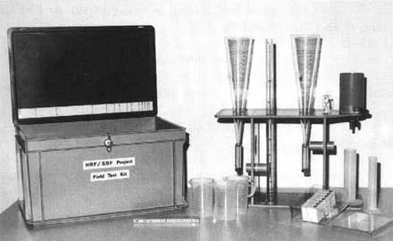
Photo 1/1 Field Test Kit (developed
and assembled by SANDEC)
2. Equipment and Procedures
2.1 Turbidity
Turbidity is measured by a test tube that has been
developed by DelAgua and which is included in a field test kit for
bacteriological (faecal coliforms) and physical/chemical analysis (pH,
conductivity, chlorine). More information on this field test kit can be obtained
from DelAgua, P.O. Box 92, Guildford GU2 5TQ, England [7]. SANDEC has adapted
the turbidity test tube by the addition of a small valve which makes turbidity
readings simpler (drainage of the filled test tube until the black circle
appears instead of a stepwise tube filling until the black circle disappears).
Test Procedure for Turbidity Analysis:
- assemble the two turbidity tubes by placing the lower in the
stand and by inserting the upper in the lower tube through the hole of the stand
- check that the valve is in a closed position
- slowly pour the water in the inclined test tube avoiding
splashing and the formation of bubbles. Fill the tube up to mark 5
- ensure that no easily settleable solids are poured into the
test tube since these would cover the black circle
- place the test tube on a white paper and avoid exposing the
equipment to direct sunlight
- observe the test tube from a vertical position and open the
valve
- close the valve as soon as you can see the black circle at the
bottom of the test tube
- record the water level, convert it into turbidity units and
record the result in the log book
- remove all water from the test tube and clean it.
Turbidity Test Tube
2.2. Filtrability
The suspended solids concentration analysis, which requires
very accurate equipment, is replaced by the filtrability test. The test will
produce relative values sufficient to monitor the efficiency of prefilters and
roughing filters in solid matter removal.
Test Procedure for Filtrability Analysis:
- remove the vessel from the filter support by lifting the clamp
and separate the porous filter disk from the filter support
- place the filter support on the stand
- close the tap (horizontal position)
- fill the filter support with water
- reinstall the porous filter disk in the filter support and
make sure that the disk is fully saturated with water
- place a filter paper No. 595 (Schleicher and Sch�ll) or any
other filter paper with a medium filterability on the filter support and press
it slightly to the porous disk to avoid air pockets below the filter paper
- place the funnel on the support and fix it with the clamp
- place a measuring cylinder under the filtrability apparatus
- pour 500 ml of the water to be tested in the funnel
- open the tap (vertical position), turn the sand clock and
record the filtered water volume in ml after 3 min. (after 1, 2 and 3 min. if
watch is available)
- remove the filter paper and the porous disk, refill the filter
support, reinstall the porous disk and replace the paper according to the
described procedure
- analyse a second water sample in the same way
- enter the results in the record sheet if they are of the same
order of magnitude (deviation + 20%), otherwise repeat the test for a third time
- remove all water from the filtrability apparatus and clean it
- plot the recorded filtrability values of the different water
samples in relation to time (min) on a graph as shown in Fig. 1/1 as it enables
the solids removal efficiency of the different treatment stages to be
determined; water to be treated by slow sand filtration should have a
filtrability value of at least 200 ml/ 3 min. and the filtrate of slow sand
filters a value of 300 ml/3 min.
Filtrability Test Installation

Fig. 1/1 Filtrability of different
raw water sand treatment stages
2.3 Settleable Solids
An adapted Imhoff cone, commonly utilised for the
analysis of waste water containing large volumes of Settleable solids, is
used here to measure also small quantities of Settleable matter. This test
enables the determination of the amount of solids removed by sedimentation.
However, the test is only useful for raw water carrying a high concentration of
Settleable solids. This test provides information on the settling
characteristics and suspension stability of the solid matter. For example, a raw
water with an initial turbidity of 50-100 NTU which shows a volume of only 1
ml/l of Settleable matter after a period of 24 hours will most probably be
difficult to treat and, hence, require pilot plant tests.
Test Procedure for the Determination of Settleable
Solids:
- start your sedimentation test in the early morning hours to
avoid taking late night readings
- check the tightness of the screw
- insert the Imhoff cone on the stand placed on a firm table
- pour 1 litre of the water to be analysed into the Imhoff cone
- record the volume of settled material after 15 min. 30 min. 1,
2, 4, 8 and 24 hours and enter the results in the record sheet
- empty the water from the test tube by removing the screw and
clean the Imhoff cone
- reinstall the screw in order not to lose it
Settleable Solids Test Cone
2.4 Suspension Stability
The stability of a suspension and settling properties of
the suspended matter can be determined by a sedimentation test. Recording
of turbidity decrease in relation to time is the simplest monitoring procedure
for such a test. The water sample must be kept undisturbed during the test
period. Therefore, small water volumes are extracted carefully and the
turbidity measured in a common turbidity meter or by the turbidity test tube
described above which, however, gives less accurate results.
Test Procedure for Suspension Stability Analysis:
- start your suspension stability test in the early morning
hours to avoid taking late night readings
- place the stability test vessel on a firm table not exposed to
direct sunlight
- fill the vessel with the water to be analysed until the water
level reaches the "0"- sign mark (required water volume about 2.5 litres)
- place the short measuring stick into the vessel
- observe the vessel through the vertical slot located at the
small end of the vessel, move the measuring stick backwards and forward until
you start to recognise the bold black line on the stick increase the sensitivity
of the measurement by using the fine line of the measuring stick in case the
bold line does not disappear when placed at the rear end of the vessel
- record the type (fine or bold line) used for reading and the
position of the stick by the scale installed at the long end of the vessel, this
record in mm is the initial turbidity value of the suspension stability test
- exchange the short measuring stick for the longer one and
install it in the vessel by placing its end at the far end of the bottom
- observe the line of the stick through the vertical slot
located at the small end of the vessel, record the position where the inclined
line of the stick disappears and note the time
- do not change the position of the measuring stick anymore nor
shake the vessel as this would disturb the stability test
- repeat your reading of the position where the inclined line of
the stick disappears after 15, 30, 60, 120 min. and after 4, 8, 24, 32 and 50
furs.
- plot the recorded values (mm) in relation to time (hrs) on a
graph similar to the one shown in Fig. 1/ 2 as it will help to analyse the
stability of the suspension
Suspension stability

Fig. 1/2 Suspension stability of
different raw waters
A special vessel without turbidity reading equipment is required
for the described test procedure. A simpler test with three beaker sand
some fine plastic tubes can be carried out in case a commercial turbidity meter
requiring small water volumes (about 25 ml) for turbidity readings is available.
Test Procedure for a Simple Suspension Stability Analysis:
- fix one small plastic tube on each wall of three beakers so
that one end of the tubes reaches the upper part (about 5 cm below the beaker's
crest) of the beaker, the other ends about 20 cm below the beaker's bottom
- place the three beakers on a firm table, fix a clamp at the
outside end of the tubes and fill the beakers with water
- carefully siphon water samples for turbidity readings out of
the beakers
- record the turbidity of the water samples
- take records after 0, 15, 20, 60, 90, 120 min and after 4, 8,
24, 32, 50 furs.
- plot the recorded turbidity in relation to time (hrs) on a
graph as shown in Fig. 1/2 as it will help to analyse the stability of the
suspension
2.5 Sequential Filtration Tests
The Turbidity, Filtrability and Suspension Stability Tests
can only give qualitative information on the amount and settling
characteristics of the solid matter found in surface water. However, these
tests do not describe particle size characteristic of a suspension, an
important parameter which greatly influences treatability of a water and, hence,
filter efficiency. Highly sophisticated and expensive apparatus such as Coulter
Counters and scattering light analysis are available to measure particle size
distributions. Since these instruments are not affordable by common water
quality laboratories, EAWAG/SANDEC has developed in cooperation with local
partners in developing countries, an alternative and simple method called
"Sequential Filtration Tests" [62] which provides reasonable information on
particle size characteristics of a suspension. The analysis only requires
special filter paper (polycarbonate capillarpore membranes, manufactured by e.g.
NUCLEPORE), a filter holder with a syringe and a turbidity meter.
Test Procedure for Sequential Filtration Test:
-
place a filter paper with the largest pore size (e.g. 14 mm) in the filter
holder filter
- a specific volume (e.g. 25 ml) through this filter paper
- record the turbidity of this first filtrate
- place a filter paper with the next smaller pore size (e.g. 10
mm) in the filter holder
- filter again 25 ml of raw water through the second filter
paper
- record the turbidity of the second filtrate
- continue with the same procedure using a sequence of filter
papers with decreasing pore size (e.g. 5, 2, 1, 0.4, and 0.1 mm)
- plot the recorded turbidity values in relation to the filter
pore sizes on a graph as shown in Fig. 1/3. It will reveal the particle size
distribution of the analysed suspension.

Fig. 1/3 Particle size distribution
of different raw
waters
Simple methods for discharge measurements
1. Introduction
Discharge measurements are necessary to control the flow
through the treatment plant. The total flow has to be distributed evenly
amongst the different filter units running in parallel. Unequal flow
distribution will usually reduce the overall performance of the filters. Flow
adjustments are required to cope with the weekly and seasonal demand
fluctuations. Furthermore, flow adjustments are also necessary before and after
cleaning and maintenance work.
Fixed installations or mobile equipment are used for
discharge measurements. Since flow control plays an important part in
treatment plant operation, the use of fixed installations is recommended.
2. Fixed Installations
Flow meters are relatively sophisticated and mechanically
sensitive. Solid matter (sand, silt) carried by the water, can easily damage the
device. It is therefore strongly recommended not to use such equipment in water
treatment plants. Flow measurements at the outlet of a clear water tank might be
the exception.
V-notch weirs are simple, strong and cheap installations,
and, therefore, most suitable for flow control in water treatment plants. Weirs
can be made from wooden boards or preferably steel or plastic plates. The weir's
discharge is measured by recording the water height above the deepest point of
the weir's crest.
A gauging rod, fixed at a distance of minimum 30 cm from
the inlet weir and marked with different colours (e.g. green in the range of the
design capacity, red for the zone above design capacity and yellow for the one
below design capacity), will ease measurements. Compared to a 90° angle
weir, V-notch weirs with a 60° angle will increase the accuracy of the
readings. Slot-shaped holes in the weir's plate and in the gauging allow and
accurate adjustment of the horizontal position. Fig. 2/1 gives more details on
the possible dimensions of a weir's plate. The relation between water height and
weir's discharge is listed in Table 2/1 and is shown as a graph in Fig. 2/2.
Table 2/1 Discharge over a 60° V-notch weir
|
Height of water hW (cm) above weir crest
|
I/s |
flow rate l/min |
m³/h |
|
1 |
0.01 |
0.6 |
0.036 |
|
2 |
0.05 |
3.0 |
0.180 |
|
3 |
0.13 |
7.8 |
0.470 |
|
4 |
0.27 |
16 |
0.970 |
|
5 |
0.46 |
28 |
1.7 |
|
6 |
0.73 |
44 |
2.6 |
|
7 |
1.08 |
65 |
3.9 |
|
8 |
1.50 |
90 |
5.4 |
|
9 |
2.02 |
121 |
7.3 |
|
10 |
2.63 |
158 |
9.5 |
Fig. 2/1 Details of a 60°
V-notch weir - View Plan

Fig. 2/1 Details of a 60°
V-notch weir - Section View
Fig. 2/2 Calibration Curve
3. Mobile Devices
The simplest method to measure water flow is to record the
filling time of a determined bucket volume. This procedure is inaccurate for
high flow rates as filling time becomes very short and easy handling is hampered
by the weight of the filled bucket.
Therefore, SANDEC has developed a more suitable flow control
device which is illustrated in Fig. 2/3. The overfalling water flows into a
bucket whose lower end is equipped with a calibrated nipple through which the
water is discharged. An equilibrium between in and out flow will soon be
established. The water height from the centre of the nipple is recorded and the
discharge read from the graph as presented in Fig. 2/4. This method does not
require a watch nor special material. A commonly used bucket or a small drum can
be used as vessel. The nipple is assembled with standard pipe fittings and does
not require great accuracy with respect to its length as shown by the graph. A
separation wall with an opening of approx. 2 cm above the vessel's bottom
creates a turbulence-free water level in the effluent's compartment. Finally,
the distance from the centre of the nipple is marked on a half cm scale in the
inner wall of the bucket. Flow rates between 6 and 30 I/min can be measured
accurately with this simple device equipped with a 1/2" nipple. Larger nipple
sizes can be used for higher flow rates and to reduce the water level difference
required by the measurement.

Fig. 2/3 Simple Flow Control Device

Fig. 2/4 Calibration Curve for 1/2"
nipple
4. Flow Control and Distributor Box
V-notch weirs are also installed in special structures used
for flow distribution and possibly also for maximum flow limitation. An
example of such a structure is illustrated in Fig. 2/5. This illustration shows
a flow control box used in the raw water supply line and placed in front of the
treatment plant. The flow which runs through the outlet pipe to the treatment
plant is measured by the V-notch weir and gauging rod. A rectangular overflow
weir in the inlet chamber limits the maximum flow through the treatment plant.
The surplus water is discharged through the overflow pipe.
The controlled total flow through the treatment plant must be
evenly distributed to the treatment units running parallel. This is achieved
by a distributor box equipped with several V-notch weirs. Since such a box
concentrates the flow control in one installation, it simplifies the
hydraulic layout of a treatment plant and increases the operational flexibility.
The inlet weirs of the subsequent treatment units can be omitted with such a
layout.
Details of a Flow Control Inlet Box

Fig. 2/5 Details of a Flow Control
Box
Salient data and features of slow sand filters
(for more detailed information see Ref. [15, 16, 17])
Design criteria
|
filtration velocity |
vF |
0.1 - 0.2 - (0.3 - 0.4) m/h |
|
area per filter bed |
A |
10 - 50 - (100) m² |
|
number of filter beds |
|
minimum of 2 |
|
height of supernatant water |
hW |
1 - (1 5) m |
|
depth of filter sand bed |
hf |
(0.6) - 0.8 - 1 m |
|
depth of underdrains system and filter support |
hs |
(0.2) - 0.3 - 0.5 m |
|
specification of filter sand |
|
effective size |
d10 |
0.15 - 0.35 - (0.6) mm |
|
uniformity coefficient |
UC 2 - 5 |
|
|
specification of filter support |
|
size/depth |
1-1.5 mm/10 cm |
|
|
(size of the support medium should be roughly 4 x the size of
|
4 - 6 mm /10 cm |
|
|
the medium to be supported) |
15 - 15 mm / 15 cm |
|
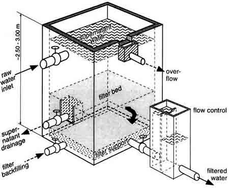
Fig. 3/1 Main Features of a Slow Sand
Filter
Common design faults and their consequences (see also
Fig. 13)
1. Inappropriate or missing flow rate control installations
® filter often overloaded or operated at frequent flow rate changes.
2. Water pressure in effluent line lower than the top level
of the sand bed ® generation of negative pressure (vacuum) in the sand
bed resulting in air release and additional filter resistance.
3. Inappropriate sand size and depth of filter bed ®
poor effluent quality (coarse sand, small depth) or short filter runs requiring
frequent cleaning (sand too fine).
4. Missing supernatant drainage system ® long
drainage periods for dewatering the filter box will affect the biology in the
sand bed
5. Slow sand filter beds with areas larger than 50 m²
® long cleaning periods will reduce or kill the biological filter
activity
6. Missing installations for watering the sand bed from
bottom to top ® air binding in the sand bed resulting in an initially
high filter resistance.
7. Installations not properly protected against unauthorized
handling.
Common operational problems
1. Turbidity and suspended solids concentration in the raw
water too high for SSF application. Turbidity should preferably be less than
10 turbidity units and the suspended solids concentration lower than 2 5 mg/l to
achieve reasonable filter operation.
2. Missing auxiliary equipment such as tools and sand
washing installations. Failing to clean and replace the sand will lead to
exhaustion of the sand bed.
3. Untrained caretakers who do not understand the SSF
process are generally not motivated to operate the treatment plant
properly.
Roughing filter theory
Filtration is more an art than a science. This saying
also applies to roughing filtration. Numerous researchers have tried to describe
the filtration mechanisms in mathematical models applying either the
phenomenological or the trajectory approach. The first one uses simple but
important variables such as filtration rate, filter size, depth and porosity to
describe filter efficiency. The second approach focuses more on transport
mechanisms of the individual particle and its behaviour in the single collector.
The phenomenological and trajectory approach will be used in this short
summary on filtration to provide some more theoretical information on the
mechanisms of roughing filtration.
Transport Mechanisms
The trajectory approach, describing the route of a clay
particle through a roughing filter, has been vividly depict in Chapter 9.2.
Additional analytical considerations regarding this mechanism are given
hereafter.
Screening, as shown in Fig 4/1, is not relevant in
roughing filters since the pore sizes are considerably larger than the particles
generally encountered in suspensions. The ratio between a clay particle of 4 mm
in diameter dp and different pore sizes do is illustrated
in the following table.
|
gravel size dg |
[mm] |
16 |
8 |
4 |
|
pore size do |
[mm] |
2.5 |
1.25 |
0.63 |
|
ratio do/dp |
[-] |
625 |
313 |
156 |
Sedimentation is the next possible process for solid matter
separation. Under the conditions described in Fig. 4/2 and shown in the
following table, the ratio between the settling distance ds travelled
by the clay particle during its flow through the pore and required total
settling height hs is very important.
|
settling velocity |
vs |
0.01 mm/s |
for a 4 mm particle |
|
pore length |
Ip |
4 mm |
for 16 mm gravel |
|
filtration rate |
vF |
0.5 m/h |
|
|
flow velocity |
veff |
0.4 mm/s |
for 35 % porosity |
|
flow time |
tf |
10 s |
(Ip / veff) |
|
settling distance |
ds |
0.1 mm |
(vs ´ tf) |
|
settling height |
hs |
1.25 mm |
(hs = 0 5 do) |
|
ratio |
hs/ds |
12.5 |
|

Fig. 4/1

Fig. 4/2
Fig. 4/3
Fig. 4/4
Interception decreases porosity and settling height hs
and enhances solid matter removal by sedimentation. However, as illustrated in
Fig. 4/3, solids accumulation in roughing filters does not significantly improve
solid matter separation. This is also presented in the following table.
|
initial porosity |
po |
35 % |
|
|
filter load |
s |
5 9/1 |
(accumulated solid per filter volume) |
|
taken up volume |
ma |
2.5 % |
for a 0.2 g/cm³ density |
|
actual porosity |
pa |
32.5 % |
(PO - ma) |
Hydrodynamic forces are capable of carrying the particles
in still water zones as illustrated in Fig. 4/4. In such prevailing conditions,
the clay particle can settle on the gravel surface as calculated in the table
below.
|
settling velocity |
vs |
0.01 mm/s |
for a 4 mm particle |
|
settling distance |
ds 2 mm |
|
|
|
settling time |
ts |
200 s |
(Is/vs) |
The "1/3-2/3 Filter Theory''
The following very simplified model elucidates the filter
removal kinetics and is based on the considerations described on page IX-4 of
Chapter 9.
|
gravel layer |
separated particles |
remaining particles |
removal [%] |
|
300 mg/l |
(removal in % per layer) |
|
1 |
100 |
200 |
33 |
|
2 |
67 |
133 |
|
|
3 |
44 |
89 |
|
|
4 |
30 |
59 |
|
|
5 |
20 |
39 |
|
|
|
|
90 |
|
6 |
13 |
26 |
(16.5% layer) |
|
7 |
9 |
17 |
|
|
8 |
6 |
11 |
|
|
9 |
4 |
7 |
|
|
10 |
2 |
5 |
|
|
11 |
1.5 |
3.5 |
|
|
|
|
99 |
|
12 |
1.2 |
2.3 |
(1.5% layer) |
|
2.3 mg/l |
|
This simple arithmetic exercise clearly proves that solid
matter separation by filtration can be described by an exponential equation
as subsequently exemplified by equation (1). However, filter efficiency does
not only depend on particle concentration but also on size and settling
characteristics. Furthermore, filter variables such as filtration rate and size
of filter medium strongly influence filter performance. Finally, the accumulated
volume of separated solids per unit of filter bed volume, known as filter load,
also determines the actual filter efficiency.
Extensive parameter tests were conducted to determine the
influence of different design parameters on the performance of horizontal-flow
roughing filters. The tests were conducted in the laboratory with filter
cells of 10 - 30 cm and 20 - 40 cm length for differently sized filter material
and different filtration rates varying between 0.5 and 2 m/h. A kaolin stock
suspension was used to simulate a suspended solids concentration of about 200
mg/l. Particle size counts were performed with a Coulter Counter TA II. These
laboratory tests are described in [10] and the data obtained were evaluated by a
multiple linear regression analysis to develop a filtration model for
horizontal-flow roughing filtration of which the following is an excerpt.
According to the established filter theory, the filter
efficiency can be expressed by the filter coefficient  [cm-1] (described by Iwasaki's equation) or
by some other collector efficiency factors
[cm-1] (described by Iwasaki's equation) or
by some other collector efficiency factors
 (1)
(1)
with c as solids concentration and x filter depth. The filter
coefficient  is a function of the interstitial
flow pattern (depending on filtration rate and pore size distribution), of the
grain surface area (depending on size and shape of the filter medium) and of
Stoke's law parameters of the water and the suspended particles (particle size,
density). Straining mechanisms are neglected and surface chemical conditions are
assumed to be constant. The volume of retained solids increases with progressive
filtration time and hence, augments the filter surface area available for
deposition but decreases at the same time the filter porosity. The degree of
filter clogging can be expressed by the volume filter load
is a function of the interstitial
flow pattern (depending on filtration rate and pore size distribution), of the
grain surface area (depending on size and shape of the filter medium) and of
Stoke's law parameters of the water and the suspended particles (particle size,
density). Straining mechanisms are neglected and surface chemical conditions are
assumed to be constant. The volume of retained solids increases with progressive
filtration time and hence, augments the filter surface area available for
deposition but decreases at the same time the filter porosity. The degree of
filter clogging can be expressed by the volume filter load  which is the volume of deposited material per unit
filter bed volume.
which is the volume of deposited material per unit
filter bed volume.  varies with position x in
the filter as well as with filtration time t.
varies with position x in
the filter as well as with filtration time t.  is therefore not a first order removal rate constant, but varies with time and
position in the filter. A more appropriate model parameter is considered to be
the particle specific filter coefficient
is therefore not a first order removal rate constant, but varies with time and
position in the filter. A more appropriate model parameter is considered to be
the particle specific filter coefficient  which
for a short time interval is constant throughout a homogeneous filter layer. The
removal of a particle fraction of the size dpi can thus be formulated by
which
for a short time interval is constant throughout a homogeneous filter layer. The
removal of a particle fraction of the size dpi can thus be formulated by
 (2)
(2)
with  as concentration of
particles of size dpi. Assuming the total filter length as a
multi-store reactor consisting of a series of small filter cells, the
performance of a HRF can be calculated on the base of the filter cell test
results. For each of the cell tests
as concentration of
particles of size dpi. Assuming the total filter length as a
multi-store reactor consisting of a series of small filter cells, the
performance of a HRF can be calculated on the base of the filter cell test
results. For each of the cell tests  may be
approximated by
may be
approximated by
 (3)
(3)
resulting in different relations of  as function of filtration velocity, grain size, particle
size and the time dependent filter load c, according to experimental conditions.
as function of filtration velocity, grain size, particle
size and the time dependent filter load c, according to experimental conditions.
Knowing  as function of the
different design variables and of the filter load
as function of the
different design variables and of the filter load  , it is possible to calculate at a certain time t in
steps of layer thickness
, it is possible to calculate at a certain time t in
steps of layer thickness  (close to the length
of the experimental filter cells) the effluent of each particle fraction by
(close to the length
of the experimental filter cells) the effluent of each particle fraction by
 (4)
(4)
and the total suspended solids concentration after an element

 (5)
(5)
The volume filter load  may be
calculated in short time intervals
may be
calculated in short time intervals  from the
particle volume balance equation for a small filter element
from the
particle volume balance equation for a small filter element 
 (6)
(6)
with  as filter velocity,
 as removed particle volume of size
dpi and
as removed particle volume of size
dpi and  as kth, time
interval from the beginning.
as kth, time
interval from the beginning.
All the dependencies of  from
the various filtration variables could be derived from the small filter cell
parameter tests by empirical analysis of the test data.
from
the various filtration variables could be derived from the small filter cell
parameter tests by empirical analysis of the test data.
The influence of the particle capture volume  on the filter coefficient was formulated according to
Ives5 and transformed to the particle specific filter coefficient
on the filter coefficient was formulated according to
Ives5 and transformed to the particle specific filter coefficient
 Starting with an initial filter coefficient
 , the filter coefficient
  becomes
 (7)
(7)
where  considers the increased
surface area available for deposition (k = constant) and the third term accounts
for the porosity decrease and the resulting increase of the interstitial
velocity.
considers the increased
surface area available for deposition (k = constant) and the third term accounts
for the porosity decrease and the resulting increase of the interstitial
velocity.  is the initial porosity and
 is a constant describing the influence of the
gradually constricting pores. Exhaustion of the filter is attained when the
suspended particles of a certain size are no longer retained (
is a constant describing the influence of the
gradually constricting pores. Exhaustion of the filter is attained when the
suspended particles of a certain size are no longer retained ( = 0) and the quantity of deposits in the pores attains
its ultimate value
= 0) and the quantity of deposits in the pores attains
its ultimate value  . It can be noticed that
 is the volume deposit of all particles
together, but varies with particle size
dpi.
is the volume deposit of all particles
together, but varies with particle size
dpi.
From the experimental results in Fig. 4/5, it may be concluded
that  does not substantially increase with
progressive filter load
does not substantially increase with
progressive filter load  . Apparently, the
effect of surface area increase for additional deposition plays a minor role in
HRF and straining effects may be completely neglected. A conservative assumption
is made by setting
. Apparently, the
effect of surface area increase for additional deposition plays a minor role in
HRF and straining effects may be completely neglected. A conservative assumption
is made by setting
k = 0 (8)
Thus, equation (7) is simplified considerably. At  = 0,
= 0,  may be expressed
as function of
may be expressed
as function of  and to
 (9)
(9)
The resulting equation for  therefore becomes
 (10)
(10)
The initial filter coefficient  and the ultimate filter load
  are determined on
the basis of the parameter test results summarised in Fig. 4/5. The general
considerations of Boller4 for the determination of the filter
constants were adapted and applied accordingly.
are determined on
the basis of the parameter test results summarised in Fig. 4/5. The general
considerations of Boller4 for the determination of the filter
constants were adapted and applied accordingly.
The value of the initial filter coefficient  depends on the process variables
  (filtration rate), dg (filter grain size) and
varies with particle size dpi. A matrix comprising the measured
initial filter coefficients for different values of the process variables and
sizes of suspended solids was transformed by a multiple linear regression
analysis to the following general equation
(filtration rate), dg (filter grain size) and
varies with particle size dpi. A matrix comprising the measured
initial filter coefficients for different values of the process variables and
sizes of suspended solids was transformed by a multiple linear regression
analysis to the following general equation
 (11)
(11)
The values for
 = 0.02
[cm-1]
= 0.02
[cm-1]
 = -0.88
 = -0.85
 = 1.0
= 1.0
were determined from 36 data points with a correlation
coefficient of 0.96.
The ultimate filter load  is
similar to the initial filter coefficient a function of the different process
variables. The volumetric filter load
is
similar to the initial filter coefficient a function of the different process
variables. The volumetric filter load  [ml/l]
was determined by the calculated and measured mass filter load
[ml/l]
was determined by the calculated and measured mass filter load  [g/l] applying a specific wet sludge density of 1.15
g/ml. The transformation of a similar matrix by multiple linear regression
analysis resulted in the equation
[g/l] applying a specific wet sludge density of 1.15
g/ml. The transformation of a similar matrix by multiple linear regression
analysis resulted in the equation
 (12)
(12)
with the following values
bo = 10 [ml/l]
 =
-0.80
=
-0.80
 = -0.18
 = 0.35
The 20 data points used showed a correlation coefficient of
0.97.
With the established equations for  and
and  , it is possible to
calculate in time steps
, it is possible to
calculate in time steps  and filter layer
elements
and filter layer
elements  the resulting particle size
distribution in function of time and space. Changes in grain size, filter
velocity and particle size distribution may be adjusted by adapting
the resulting particle size
distribution in function of time and space. Changes in grain size, filter
velocity and particle size distribution may be adjusted by adapting  . Hence, the filter performance of a full scale HRF can
be simulated by the arrangement of a number of short filter layer elements each
specified with its own
. Hence, the filter performance of a full scale HRF can
be simulated by the arrangement of a number of short filter layer elements each
specified with its own  . The increment of
filter load within each element is calculated over a time step
. The increment of
filter load within each element is calculated over a time step  and its influence on
  is considered in the next time interval.
The above studies have only focused on the physical removal
mechanisms. Roughing filters may, however, also develop biological activities
which enhance particle removal. Such investigations were carried out with
suspensions containing clay (kaolin), algae (Scenedesmus) or a combination as
described in [11]. The laboratory tests were also evaluated by multilinear
regression models. The following equations were obtained for steady state
conditions.
|
for kaolin: |
|
Ce/Co = 0.188 + 0.0231 media +0.136 flow -
0.101 depth |
|
for Scenedesmus algae: |
|
Ce/Co = - 0.170 + 0.253 flow + 0.142 media
- 0.021 depth - 0.0128 media2 |
|
for kaolin + algae: |
|
Ce/Co = 0.0280 + 0.0902 flow + 0.0181
media - 0.0558 depth |
|
|
where |
|
|
- Ce is the effluent concentration in [mg/l] |
|
- Co is the inlet concentration in [mg/l] |
|
- "media" is the gravel size in [mm] |
|
- "flow" is the filtration rate in [m/h] |
|
- "depth" is the filter length in [cm] |
Fig. 4/5 Filter Coefficient in
Relation to Filtration Rate, Grain Size and Filter Load
This research has also revealed that filter efficiency is
dependent on design variables such as filtration rate, gravel size and filter
length. However, as outlined in other investigations [36, 47], flow direction
is of minor importance for filter performance. These laboratory tests have
shown that kaolin removal is enhanced by the addition of algae which destabilise
the clay into aggregates that are more efficiently removed by roughing
filtration. However, hydraulic filter cleaning is more difficult when the clay
is coated with organic matter. Hence, the presence of biomass in a roughing
filter probably does enhance solid matter separation but may also hinder
hydraulic filter cleaning.
The chemical properties of the suspension; i.e., the suspension
stability is, however, not taken into consideration in these filter models.
Filter models are not universally applicable to all types of raw water as
filter efficiency is strongly influenced by the raw water quality. Such
semi-empirical models may therefore be used to investigate the overall influence
of specific design parameters or to optimise treatment plant design on the basis
of a comprehensive pilot plant field test
programme.
Pilot plant design examples
Pilot plant tests must be carefully planned, designed and
monitored to achieve conclusive results required for design development and
performance prediction of future full-scale treatment plants. Implementation of
the following aspects are important in pilot plant tests:
· gravity flow should be
applied in a pilot plant. Due to the unreliable operational system and possible
unavailability of pumps with small discharge rates, pumps should thus be avoided
whenever possible, except for raw water lifting. This may be carried out with a
higher discharge pump to fill a raw water tank twice a day.
· V-notch weirs or small
orifices are appropriate devices for flow control. Use of clamps or small
valves is not recommended as they rapidly clog and are, thus, not capable of
maintaining a constant flow rate. Constant flow rate devices such as a floating
inlet pipe (see also Fig. 33 on page IX-8) are a further option for flow
control.
· the diameter of the filter
columns should not be too small to reduce sidewall short-circuiting in pilot
filters. The ratio recommended for dcolumn/dmedia should
be 25. However, since the media is not densely compacted along the sidewalls,
the recommended ratio can be reduced for roughing filters.
· flow rates should not be
too small; i.e., not lower than 0.5 l/min., as they are difficult to
maintain at a constant level.
· the hydraulic load on
the pilot unit should be close to the highest recommended value, e.g. slow sand
filter units should be operated at 0.2 m/h filtration rate. This will reduce the
filter running period and allow more filter runs within a given period.
· the size of the pilot plant
units should not be too small and meet the aforementioned recommended
minimum flow rate of 0.5 l/min. The following minimum pipe diameters are
recommended:
|
upflow roughing filter |
|
for VF min. = 0.6 m/h, |
Fmin. = 30 cm |
Q = 0.6 l/min. |
|
slow sand filter |
|
for VF min. = 0.2 m/h, |
Fmin. = 50 cm |
Q = 0.7 l/min. |
· the structure of the pilot
units must be sturdy. Concrete rings, plastic pipes, steel containers or
concrete blockwork are adequate structures. Wooden boxes are not recommended as
they are often not watertight. The structures can be temporary installations
which may be used several times in different places.
· the tested filter material
must be the same as the one foreseen for full-scale treatment plants. It
must be clean and adequately graded.
· water samples for water
quality analysis should be taken only at filter inlet and outlet. Other sampling
points in the filter bed should be installed only in large pilot units where
sampling must be conducted with great care in order not to resuspend the solids
accumulated in the filter bed.
· the pilot plant should be
protected; i.e., shaded to prevent water heating by the sun, roofed to avoid
disturbance by heavy rainfall and enclosed to hinder entrance of unauthorised
people.
· local staff are preferably
employed to carry out the monitoring programme. At least two persons should
be trained by the project engineer responsible for the field test studies. He
will also have to visit the pilot plant periodically, supervise the local staff
and evaluate continuously the field test results.
· the monitoring programme
is mainly carried out by local staff with field test equipment stored at the
site. Laboratory staff may be involved to analyse the water for its specific
water quality parameters. A possible field test monitoring programme is proposed
in Table 5/1.
Table 5/1 Field Test Monitoring Programme
|
control / sampling frequency |
|
Parameter |
raw water |
pretreated water by roughing filter |
treated water by slow sand filter |
|
flow rate |
- |
daily |
daily |
|
filter resistance |
- |
weekly |
every 2 days |
|
turbidity |
daily |
daily |
daily |
|
filtrability |
weekly |
weekly |
weekly |
|
settleable solids |
at high turbidities |
- |
- |
|
Fecal coliforrns |
monthly |
monthly |
monthly |
|
chemical substances |
if required at defined intervals |
- |
if required at defined intervals |
The following three figures illustrate possible pilot plant
layouts. The first example shown in Fig. 5/1 uses concrete or plastic pipes
to field test upflow roughing filters and slow sand filters. The second
example shown in Fig. 5/2 illustrates the possible use of a steel container
fitted with a horizontal-flow roughing pilot filter. Since the steel
container is mounted on a mobile loading platform of a truck, it can be used
elsewhere. The third example also illustrates a pilot testing unit for
horizontal-flow roughing filters. Fig. 5/3 shows the simplest structure
consisting of an excavated trench coated with a plastic sheet and filled with
gravel filter material. To allow proper installation of the filter material,
open containers are necessary for horizontal-flow roughing pilot filter units
since the filling of gravel would be difficult with pipes.
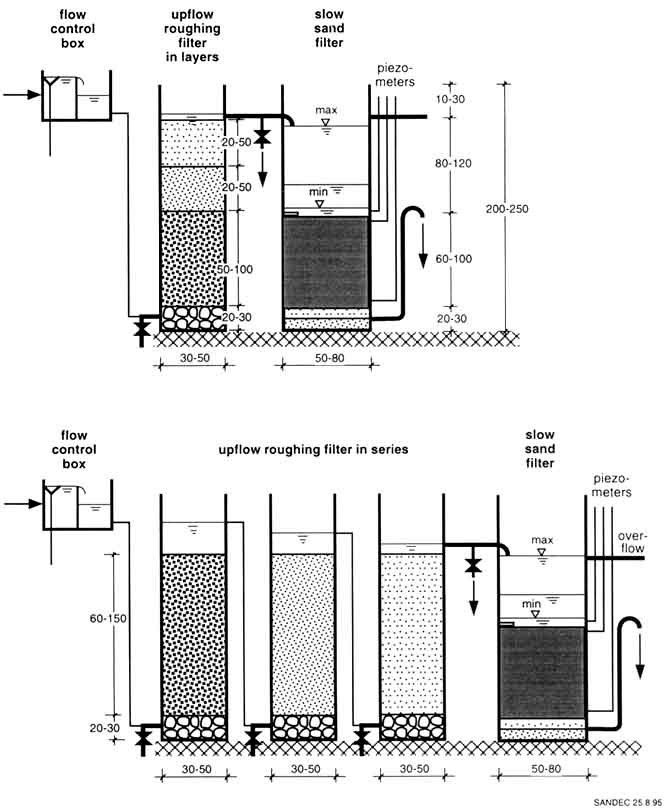
Fig. 5/1 Pilot Plant Examples
consisting of Upflow Roughing Filters and Slow Sand Filters
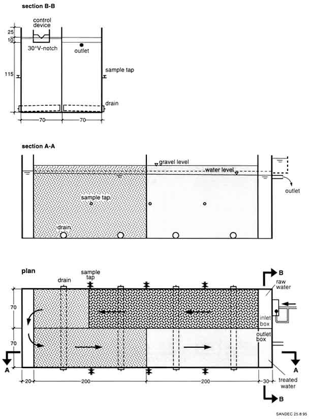
Fig. 5/2 Example of a Mobile Pilot
Plant for a Horizontal-flow Roughing Filter
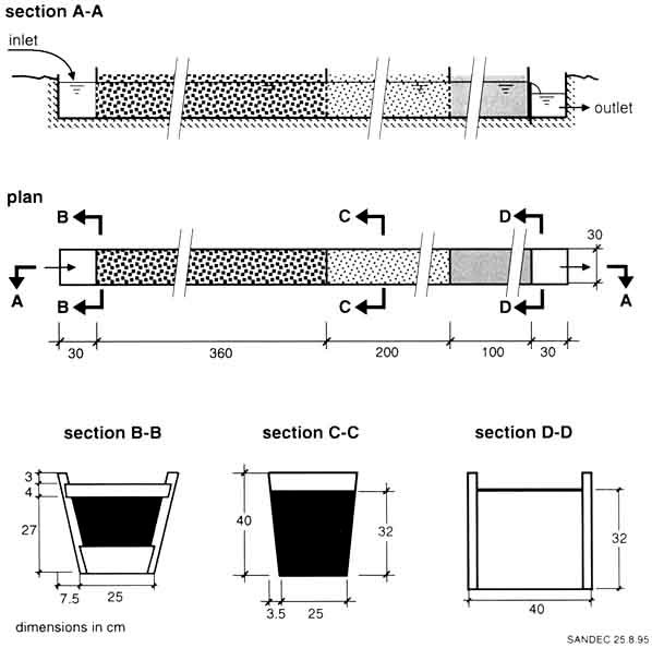
Fig. 5/3 Example of a Trench Cut
Pilot Plant for a Horizontal-flow Roughing
Filter
Roughing filter design examples
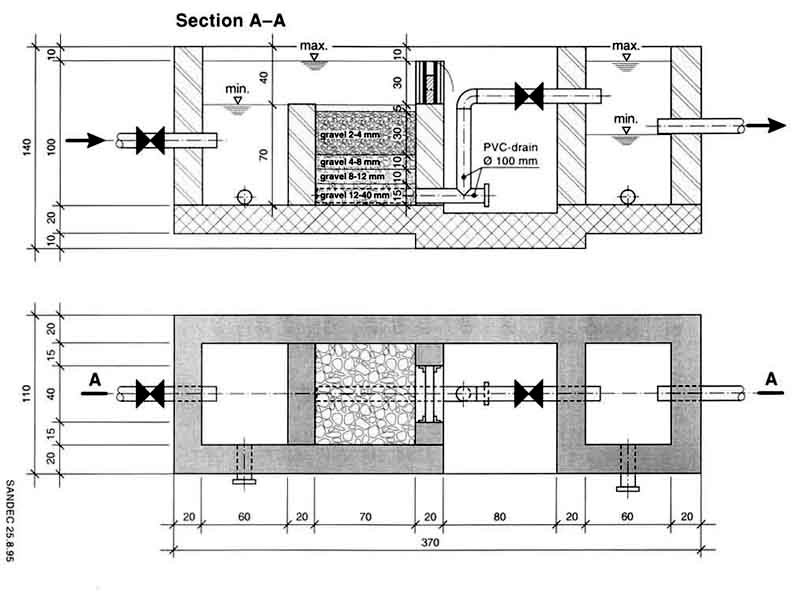
Design Example of a Dynamic Filter
Annex 6/1

Design Example of an Intake Filter
Annex 6/2

Design Example of a Horizontal-flow
Roughing Filter
Annex 6/3

Design Example of an Upflow Roughing
Filter Annex 6/4

Possible Layouts for the Integration
of Upflow Roughing Filters into Existing Sedimentation Tanks or Slow Sand
Filters Annex 6/5
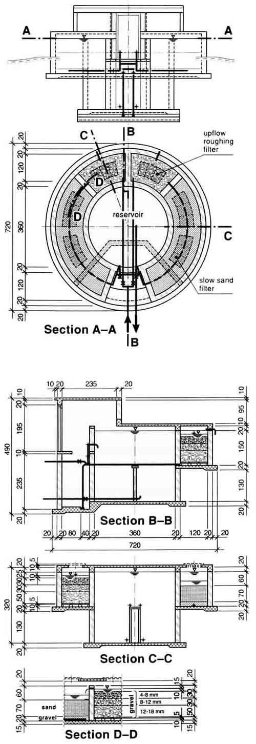
Design Example of a Compact Water
Treatment Plant Annex 6/6
Algorithm for the Design of Surface
Water Treatment Schemes Annex
6/7
Outline for caretaker training
1. Introduction
Proper caretaker training in operation and maintenance of water
supply installations is, in many cases often seriously neglected. Incorrect use,
damage and finally abandoned installations are generally the consequences of
such a neglect. However, since sound and economic operation of a water supply
system requires, among other prerequisites, well-trained and skilled manpower
comprehensive training of local staff is essential.
Transfer of knowledge is the main goal of a training programme.
However, since motivation and guidance of the caretakers are also important
components, training should therefore not be limited to a short-tem introductory
course.
Caretakers are preferably trained in their local language by
supervisors attached to the operation and maintenance section of the responsible
institution. These supervisors will also visit the water supply schemes on a
regular basis, check their proper operation, support local staff in their
activities, and maintain an exchange of information between field and office
personnel.
A training programme is briefly outlined below. The subject area
of the programme only covers the treatment process as more comprehensive
training guidelines for the operation and maintenance of rural water supply
schemes have already been published by IRC [63].
2. Schedule
An ideal training programme may be divided into three parts.
Timing, aim, location and duration of the three parts are summarised in Table
7/1.
3. Outline of the Syllabus
The topics to be covered by the different parts of the training
programme are suggested hereafter. The list may be incomplete and may possibly
need to be adapted to local conditions.
Part 1:
- visit of an existing treatment plant comprising RF and
SSF
-explanation of the treatment process and operation of the plant
-
discussion of the water quality problems faced by new schemes
- assessment of
the interest of future users in water treatment
Part 2: - main objectives of water treatment
- main features and processes of RF and SSF
- filter
operation, especially
· discharge measurements and
adjustment
· determination of filter
resistance
· filter (re)starting and cleaning
procedure
· hydraulic and manual filter
cleaning
· gravel and sand cleaning
· water sampling
- conduct simple water quality tests (turbidity, filterability,
settleable solids)
- monitoring the treatment plant (keeping of logbook)
-
maintenance work
- annual work plan
Part 3:
- refresh and consolidate the basic training course (Part
2)
- on-site training in plant operation and maintenance
- review and
discuss operational problems encountered
- inspect the installation and
organise major maintenance work
- review of logbook and monitoring results
Table 7/1 Training Programme
|
Part |
Timing |
Aim |
Location/Duration |
|
1 |
pre-project phase
or
before/during construction of new
treatment plant |
presentation of treatment process to future users and
motivation |
existing RF and SSF plant
-
1 day |
|
2 |
during or at the end of the construction phase
|
basic training of future caretakers in the operation and
maintenance of RF
and SSF |
existing or new RF and
SSF plant
-
3-5 days |
|
3 |
during the operational phase
|
supervision, guidance, support of the operation and maintenance
of RF
and SSF (information exchange) |
on the site
-
by regular field visit |
Monitoring of filter operation
1. Aim and Procedure
The aim of a monitoring programme is to:
- assess treatment plant performance
- establish guidelines
for treatment plant operation
- improve treatment plant operation and
efficiency
The caretaker carries out the field test and monitors, with the
help of a logbook, operation and performance of the treatment plant. The
supervisor, attached to the operation and maintenance section of the responsible
institution, controls the monitoring programme of the caretaker by means of
regular visits, takes water samples to be analysed in the laboratory, and
summarises the monitoring results in annual reports.
2. Field Records
The monitoring programme has to cover the quantitative and the
qualitative aspects. Discharge measurements characterise the operational
conditions of the treatment plant and provide the quantitative information.
Water quality tests allow qualitative assessment of the treatment process.
Treatment plant operation requires flow control and adjustments on a daily
basis. The water quality tests should also be carried out regularly; i.e.,
weekly. The equipment necessary for discharge measurements and water quality
tests must therefore always be available at every treatment plant.
A field monitoring programme proposal is summarised in Table
8/1.
3. Bacteriological and Chemical Water Analyses
Bacteriological and chemical water analyses require more costly
equipment generally not available at every treatment plant. The tests should
also be performed by experienced staff. It is therefore recommended for the
supervisor to perform such tests either at the site with field test equipment
brought from the laboratory, or to take samples which will be analysed in the
laboratory. Since field testing excludes the risk of delay and mishandling of
the water samples, it should therefore be applied whenever possible, provided
the equipment is properly maintained and checked prior to each field visit.
A bacteriological and chemical monitoring programme proposal is
summarised in Table 8/2.
4. Field Visits
The supervisor will personally conduct on-site training of the
caretaker, and will also be present during the initial stars of treatment plant
operation. He will later assist the caretaker in his daily activities and
supervise operation, maintenance and monitoring of the plant. Frequency of his
visits is dependent, among other criteria, on the ability of the caretaker to
operate his water supply system. However, field visits will at first be carried
out weekly, then monthly and later every two to three months.
Such a post-project assistance is essential to ensure proper use
of the installations, to identify possible problems at an early stage, and to
compile practical experience gained for future projects.
5. Evaluation
The supervisors will compile the results of the monitoring
programme in annual reports which will also contain the data sheets of the field
test records and possible laboratory analyses. They will also comprise a short
description of the operational experience (plant performance, encountered
practical problems, exceptional events) and planned activities (operational
modifications of the plant, major maintenance work, etc.).
Table 8/1 Field Monitoring
|
parameter |
record |
frequency |
|
flow rate |
RF + SSF |
every 2 days |
|
filter resistance |
RF |
1 x / week |
|
filter resistance |
SSF |
every 2 days |
|
of raw water |
|
|
turbidity |
and RF + SSF effluents (at |
2 x / week |
|
filtrability |
high turbidity, filtrate of |
(daily at periods of high |
|
each RF gravel pack) |
turbidity) |
|
settleable solids |
raw water |
1 x / week |
Table 8/2 Bacteriological and Chemical Monitoring
Programme
|
analysis |
sample |
frequency |
|
E.coli or total coliforms or
Fec. Strept. |
raw water and RF + SSF
effluent |
monthly for the first half
year, later occasionally |
|
pH |
|
|
|
conductivity |
|
|
|
total hardness |
|
|
|
alkalinity |
raw water |
every 2 months |
|
Ca2+ |
|
|
|
Mg2+ |
|
|
|
susp. solids cone. |
|
|
Conversion Table
|
length |
1 m |
= |
3.2808 ft |
1 ft |
= |
0.3048 m |
|
1 mm |
= |
0.0394 in. |
1 in. |
= |
25.4 mm |
|
area |
1 m² |
= |
10.7639 ft2 |
1 ft2 |
= |
0.0929 m² |
|
1 cm² |
= |
0.1550 in.2 |
1 in.2 |
= |
6.452 cm² |
|
volume |
1 m³ |
= |
35.31 ft3 |
1 ft3 |
= |
0.0283 m³ |
|
1 litre |
= |
0.2642 gal |
1 gal |
= |
3.785 litre |
|
velocity |
1 m/h |
= |
3.2808 ft/h |
1 ft/h |
= |
0.3048 m/h |
|
1 m/s |
= |
3.2808 ft/s |
1 ft/s |
= |
0.3048 m/s |
|
flow rate |
1 m³/h |
= |
35.31 ft3/h |
1 ft3/h |
= |
0.0283 m³/h |
|
1 m³/s |
= |
35.31 ft3/s |
1 ft3/s |
= |
0.0283 m³/s |
|
1 m³/h |
= |
264.2 gal/h |
1 gal/in |
= |
3.785 litre/h |
|
1 m³/s |
= |
264.2 gal/s |
1 gal/s |
= |
3.785 litre/s |
|
filtration rate |
1m/h |
= |
0.4092 gpm/ft2 |
1 gpm/ft2 |
= |
2.444 m/h |
|
temperature |
1°C |
= |
(1°F - 32)x5/9 |
1°F |
= |
9/5°C + 32 |
Acknowledgements and credits
Financial Support
SANDEC's Roughing Filter Project has been cofinanced by
- the Swiss Development Cooperation (SDC)
- the Swiss Federal
Institute of Environmental Science and Technology (EAWAG)
- the City of
Zurich the Swiss Gas and Water Industry Association (SVGW)
- the Zurich Water
Supply
Major Cooperation Partners
Numerous local institutions and organisations cooperated with
SANDEC in the Roughing Filter Project. We would like to express our appreciation
for their interest and efforts. Special thanks go to:
- CINARA, Gerardo Galvis
Instituto de Investigaci�n y
Desarrollo en Agua Potable, Saneamiento B�sico y
Conservaci�n del Recurso
H�drico
A.A. 25157, Cali, Colombia
- DelAgua, Mauricio Pard�n
c/o Centro Panamericano de
Ingenier�a Sanitaria y Ciencias del Ambiente (CEPIS)
Casilla Postal 4337,
Lima 100, Peru
- UNR, Ana Mar�a Ingallinella
Dept. de Hidr�ulica e Ingener�a
Sanitaria
Universidad Nacional de Rosario
Riobamba 245 bis, 2000 Rosario,
Argentina
- Afrowood Ltd., Kolly Dorcoo
P.O. Box 5001, Accra-North,
Ghana
- Helvetas Cameroon, Thomas Zimmermann
P.O. Box 114, Bamenda,
Cameroon
- UDSM, Tolly Mbwette
Faculty of Engineering, University of
Dar es Salaam
P.O. Box 351 31, Dar es Salaam, Tanzania
- EWW, Mesfin Shenkut
Ethiopian Water Works
P.O. Box
30504, Addis Ababa, Ethiopia
- BNHP, Sadig Abdel Basit
Blue Nile Health Project
P.O.
Box 101, Wad Medani, Sudan
- ZHAS, Xu Xiang-Kuan
Zhejiang Health and Anti-Epidemic
Station
17 Lao Zheda Road, Hangzhou 310009, China
Reviewers
For their helpful comments and suggestions we would like to
thank the following invited reviewers:
-Gerardo Galvis, CINARA, Cali, Colombia
-Mauricio Pard�n,
PAHO, Guatemala
-Ivanildo Hespanhol, ex WHO, S�o Paulo, Brazil
-Luiz di
Bernado, USP, S�o Paulo, Brazil
-Anna Maria Ingallinella, UNR, Rosario,
Argentina
-Sergio Caporali, CEPIS, Lima, Peru
-Kolly Dorcoo, Afrowood, Accra, Ghana
-Thomas Zimmermann,
Helvetas, Bamenda, Cameroon
-Tolly Mbwette, UDSM, Dar es Salaam,
Tanzania
-Mesfin Shenkut, ex SDR, Addis Ababa, Ethiopia
-Amadeus Maiga,
EIER,, Ougadougou, Burkina Faso
-Gunnar Shultzberg, ex UNDP/WB, Nairobi,
Kenya
-E. Masendu, UoZ, Hahare, Zimbabwe
-Gerhard Offringa, WRC, Pretoria,
South Africa
-R. Paramesivan, NEERI, Nagpur, India
-Srilal
Wijegoonewardene, NWDB, Mount Lavinia, Sri Lanka
-Chongrat Polprasert, AIT,
Bangkok, Thai land
-Niu Shiru, CAPM, Beijing, China
-Xu Xiang-Kuan, ZHAS,
Hangzhou, China
-Jan Teun Visscher, IRC, The Hague, The Netherlands
-Nigel
Graham, Imperial College, London, England
-Barry Lloyd, University of Surrey,
Guildford, England
-Brian Clarke, University of Surrey, Guildford,
England
-Robin Collins, University of New Hampshire, Durham,
USA
-Gourisankar Ghosh, Unicef, New York, USA
-John Kalbermatten, ex WB,
Washington, USA
-Jos� Hueb, WHO, Geneva, Switzerland
-Ernst Tr�eb, ETH, Winterthur, Switzerland
-Maarten
Schalekamp, ax-President IWSA, Zurich, Switzerland
-Karl Wehrle, SKAT, St.
Gallen, Switzerland
-Armon Hartmann, SDC, Berne, Switzerland
-Paul Peter,
SDC, Berne, Switzerland
-Markus Boller, EAWAG, Switzerland
Drawings
All Figures and Illustrations were developed by the author.
However, the following drawings were adapted from original designs cited here:
|
Fig. 5/2 adapted from |
Village Water Reservoirs Project, Tamale, Ghana |
|
Fig. 5/3 adapted from |
Pilot Plant Plumbon, Indonesia
CDC, Centre for Developing
Countries, Lyngby, Denmark |
|
Fig. 6/1 adapted from |
Guzang II, Helvetas, Bamenda, Cameroon |
|
Fig. 6/2 adapted from |
Jomatt College, Helvetas, Bamenda, Cameroon |
|
Fig. 6/3 adapted from |
Water Treatment Plant CIDER, Restrepo
CINARA, Cali, Colombia
|
|
Fig. 6/4 |
Bambui, Helvetas, Bamenda, Cameroon |
|
Fig. 6/6 |
Nsuke, Helvetas Bamenda, Cameroon |
Photos
All Photos were taken by the author except for:
|
Photo on page V-4 |
DelAgua, Peru |
|
Photo on page V-7 |
Roland Schertenleib, SANDEC |
|
Photo on page VII-5 |
Toni Lejeune, SDR |
|
Photo on page VIII-4 |
Arnold Furrer, SDR |
|
Photo on page Xl-3 |
DelAgua, Peru |
|
Photo on page XII-8 |
Patrik Lund, CDC |
|
Photo on page XIII-3 |
Toni Lejeune, SDR |
|
Photo on page XIV-11 |
Andrea Pozzi, ETH |
Back covert
This publication presents the concept, design and field
experience of roughing filters applied as pretreatment prior to slow sand
filters. It describes treatment processes which convert turbid surface water
into safe drinking water. The presented treatment methods are simple, efficient
and reliable and, therefore, appropriate for rural water supply schemes.
Surface water treatment generally requires at least two
treatment steps. The first step, also called pretreatment, concentrates mainly
on the removal of solids. Prefiltration by roughing filters is a simple and
efficient process for solid matter separation. However, roughing filters also
contribute to a bacteriological water quality improvement. The second step,
commonly considered as main treatment, is applied especially to remove or
destroy the remaining microorganisms by slow sand filtration and chlorination.
This manual mainly focuses on the design, construction and
operation of prefilters and roughing filters. It is recommended as textbook for
teachers and students, as design manual for engineers and as operation and
maintenance guidelines for technicians. The manual draws its valuable
information from a vast field experience documented by the small stories
scattered throughout the text.
ISBN:
3-908001-67-6