 |
| ||||||||||||||||||||||||||||||||||||||||||||||||
|
| ||||||||||||||||||||||||||||||||||||||||||||||||
Institut f�r berufliche Entwicklung e.V.
Berlin
Original title:
Arbeitsmaterial f�r den
Lernenden
“Herstellen von Deckenkonstruktionen”
Author: Rolf Becher
First Edition © IBE
Institut f�r berufliche Entwicklung e.V.
Parkstra�e
21/23
13187 Berlin
Order No.: 93-35-3604/2
|
| ||||||||||||||||||||||||||||||||||||||||||||||||
1. Purpose of Ceilings
Ceilings serve architectonic, physical and statical purposes.
Table 1: Purpose of ceilings
In addition to statical functions, such as stiffening of the building or room and taking up of loads, they should also meet fire-resisting, sound-insulating and heat-insulating requirements. They must withstand the air humidity and, depending on the use of the building, be protected against penetration of moisture.
Basically the construction of a ceiling features three components:
- bare ceiling (supporting and stiffening structure of the ceiling)
- top ceiling (floor construction on the bare ceiling)
- subceiling (covering the bottom side of the bare ceiling).
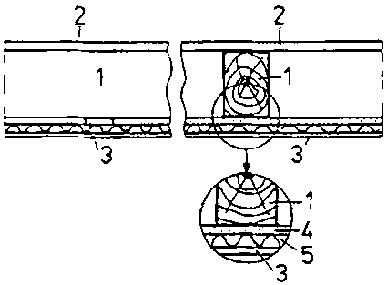
Figure 1
Basic construction of a ceiling
1 bare ceiling (supporting structure), 2 top ceiling, 3 subceiling, 4 additional rafters or thatched ceiling, 5 plaster base (wood-wool boards or woven reed)
The supporting structure of a ceiling may be designed as solid ceiling or as beam (joist) ceiling, depending on the load. The subceiling may also be fixed to the bare ceiling as false ceiling.
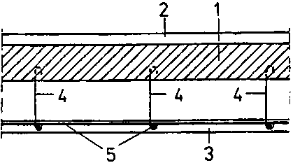
Figure 2
Construction of a false ceiling
1 bare ceiling, 2 top ceiling, 3 false ceiling (stucco ceiling), 4 non-corrosive round steel bars as suspension bars, 5 non-corrosive reinforcing steel bars
|
| ||||||||||||||||||||||||||||||||||||||||||||||||
2. The Wooden Beam Ceiling
The wooden beam ceiling is a typical beam ceiling.
The supporting structure (the bare ceiling) consists of wooden beams (or joists) placed over a room with a calculated pitch size (spacing).
The infilling (strut members) between the wooden beams depends on the purpose of the building.
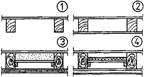
Figure 3
Construction of a wooden beam ceiling, depending on the use of the building
(1) wooden beam ceiling with top ceiling only(2) wooden beam ceiling with top ceiling and subceiling (protection against trickling matter)
(3) wooden beam ceiling with sound and heat insulation
(4) wooden beam ceiling with heat insulation only
The infilling of a heat-insulating wooden beam ceiling differs from that of a sound-insulating ceiling.A wooden beam ceiling, which shall neither be heat-insulating nor sound-insulating, has no infilling at all.
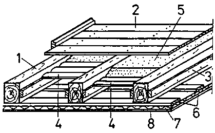
Figure 4
Components of a wooden beam ceiling with infilling
1 wooden beam, 2 (open-nail) flooring, 3 beam strip, 4 dead floor - laggings - (peeled, trimmed slabs; joints filled with clay), 5 slag (sound and heat insulation), 6 additional rafters (distance about 500 mm), 7 woodwool board, 8 ceiling plaster
Figure 4 shows the infilling of a sound-insulating and heat-insulating wooden beam ceiling.
The structural components of bare ceiling, top ceiling and subceiling described therein need not exist with any wooden beam ceiling.
Why need any wooden beam ceiling not consist of such structural components?
____________________________________________
Which structural components must any wooden beam ceiling consist of?
____________________________________________
If a wooden beam ceiling is to be protected against trickling matter only, the subceiling (protection against trickling matter) may be made of boards planed on one side, of particle board or other material.
Which rooms require protection against trickling matter?
____________________________________________
|
| ||||||||||||||||||||||||||||||||||||||||||||||||
3. The Framing
The wooden beams placed over a room are called (wooden beam) framing. (See Fig. 8)
For easy identification of the individual wooden beams of a framing for a building, they are provided with a “floor mark” and “jointing mark” and numbered with Roman numerals.
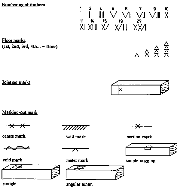
Table 2: Carpenter’s marks
The beam marks are cut in by a mortise chisel or done with a pencil.
Marking is always done from the left to the right and from the bottom to the top.
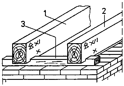
Figure 5
Marking of wooden beams
1 intermediate beam No. 15 in the 2nd floor
ceiling,
2 intermediate beam No. 16 in the 2nd floor
ceiling,
3 wall plate
The left-hand side always means looking from the front of the building in the plan view.
The wooden beams of one framing may have different widths but they should all have the same height to avoid levelling for the flooring to be provided.
If the beams of one framing are not loaded by concentrated loads (such as a joining beam of an attic framing), they should be placed at equal spacing.
If a wooden beam ceiling is interrupted by openings (such as stairs, chimneys, ventilation ducts), which cannot be located between the clear distances of the beams, a beam trimming will be necessary.
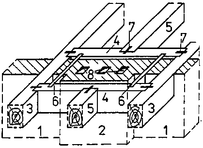
Figure 6
Chimney beam trimming
1 brickwork (centre wall), 2 chimney (three tubes), 3 trimmer beam, 4 beam trimming, 5 tail beam, 6 filling timber, 7 cramp, 8 smoke tube
For chimney beam trimmings a certain distance of the beams from the inner edge of the flue (smoke tube) is to be kept!
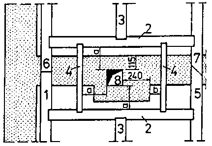
Figure 7
Minimum distances of the beams from the smoke tube
1 passing tail beam, 2 beam trimming, 3 tail beam, 4 filling
timber, 5 trimmer beam, 6 joining of timbers by straight joint, 7 joining of
timbers by angular joint, 8 smoke tube
a = 200 mm or
more
b = 60 mm or more
Why must a certain distance from the smoke tube be kept for chimney trimmings?
____________________________________________
Why should all beams of one framing have the same height?
____________________________________________
Which distance from the smoke tube must the beams of a chimney trimming have?
____________________________________________
The designation of the beams is derived from their location within the framing. From the designation the carpenter tells where to place the respective beam in the framing of the building.
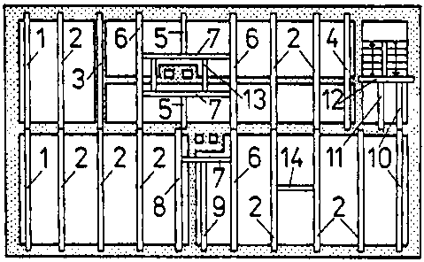
Figure 8
1 Verge or gable beam
- at a distance of 20 mm from the wall and parallel to the gable wall.
2 Intermediate beam
- any beam between the listed beams (1) to (13).
3 Wall beam
- immediately above a wall that is parallel to the straining direction of the beams.
4 Passing beam
- at a distance of 20 mm from a wall which is parallel to the straining direction of the beams. (The beam is passing along the wall)
5 Tail beam
- parallel to the straining direction of the beams and ending in a beam trimming.
(The beam is tailed into the beam trimming)
6 Trimmer beam
- parallel to the straining direction of the beams and accomodating a beam trimming.
7 Beam trimming
- square to the straining direction of the beams and either ending in a trimmer beam at both ends or resting on a wall at both ends or ending in a trimmer beam at one end and resting on a wall at the other end.
8 Passing trimmer beam
- at a distance of 20 mm from a partition wall and accommodating a beam trimming.
9 Passing tail beam
- at a distance of 20 mm from and parallel to a partition wall and ending in a beam trimming.
10 Verge tail beam for stair landings
- like (1) above, ending in the stair apron.
11 Tail beam for stair landings
- parallel to the straining direction of the beams and ending in the stair apron.
12 Stair apron
- square to the straining direction of the beams and accommodating the tail beams for the stair landing.
13 Filling timber
- square to the beam trimmings and accommodating the flooring within the area of a ceiling opening.
14 Lustre filling timber
- between two beams and square to them, serves for accommodation of a heavy ceiling fitting (lustre).
At which wall must the verge beam be placed?
____________________________________________
Which distance from the wall must the passing beam or the verge (gable) beam have?
____________________________________________
What is the purpose of the filling timber in a framing?
____________________________________________
In order to place the beams of one framing at equal spacing (pitch), the pitch size is to be calculated first.
According to this size, guiding marks are then scribed on the wall plate or directly on the wall and provided with the jointing mark. (See Fig. 10 and Fig. 11).
Working “off the jointing mark” should be given preference over the other two possibilities because the jointing mark remains visible for checking.
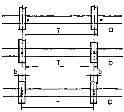
Figure 9
Working with jointing marks
a working “off the
jointing mark”,
b width of wooden beam, c working
“from centre to centre”,
b working “on the jointing
mark”, T pitch size
Why does the jointing mark remain visible?
____________________________________________
What does the term “guiding mark” mean?
____________________________________________
|
| ||||||||||||||||||||||||||||||||||||||||||||||||
4. The Attic and Collar-beam Framing
The attic framing is the top framing.
It supports the roof structure.
All partition walls and the centre wall are ending beneath the attic framing. Fire walls, however, extend until beneath the roofing.
Because the attic framing supports the roof structure, the wooden beams of this framing may have different widths. They all should, however, have the same height!
Why should all wooden beams of the attic framing have the same height?
____________________________________________
For equidistant distribution of the beams it is important that the joining beams should not exceed a distance of 4000 mm.
What purpose do the joining beams serve in the attic framing?
____________________________________________
It is recommended to fix the location of the joining beams and then to calculate the pitch size for the intermediate beams between them.

Figure 10
Pitch size between joining beams
1 joining beam, 2 intermediate beam, 3 wall plate, b1, b2 width of wooden beams, T pitch size, Lr arithmetical length for pitch size calculation
The pitch size can be calculated to formula (1) in section 5 hereof. In addition to the floor mark and a number, the joining beams also have a marking-out mark.
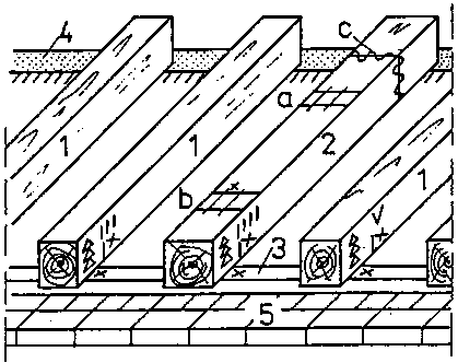
Figure 11
Wooden beams marked with floor mark, jointing mark, number and marking-out marks
1 intermediate beam, 2 joining beam, 3 wall plate, 4 inner or
centre wall, 5 outer wall
a marking-out mark for
straight tenons, b marking-out mark for angular tenons, c void
mark
Why do the wooden beams of a framing have a number and a floor mark?
____________________________________________
What are marking-out marks?
____________________________________________
The collar-beam framing is no typical wooden beam framing. It is mainly applied in a rafter roof. The purpose of the collar beams is to stiffen the rafter pair of a rafter roof.
But collar beams may also be built into a purlin roof when the roof room is very high and shall be used effectively.
|
| ||||||||||||||||||||||||||||||||||||||||||||||||
5. The Pitch Size
The wooden beams of a wooden beam ceiling should be placed at equal distances so as to equally distribute the load on all beams.
If the distances between the wooden beams are not shown in the drawing, the pitch size is to be calculated.
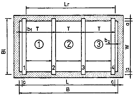
Figure 12
Determination of the pitch size
(1) bay 1, (2) bay 2, (3) bay 3
Lr length required for the calculation, BL length of wooden beam, T pitch size (beam spacing), B clear width of the room, L length to be distributed, a bearing length, b1, b2 width of wooden beams, c minimum distance of wooden beams from the wall, 1, 2, 3, 4 wooden beams
The pitch size depends on the thickness of the flooring and is calculated to formula (1).

T = pitch size (distance of wooden beams)
Lr = length required for the calculation
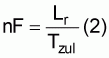
nF = number of bays
The number of bays is determined by means of formula (2).
Tzul = pitch size depending on the thickness of the flooring
20 mm thick flooring - - - pitch size Tzul = 600 mm
24 mm thick flooring - - - pitch size Tzul = 800 mm
30 mm thick flooring - - - pitch size Tzul = 1000 mm
If the resulting nF is a decimal fraction, it is to be rounded off to bring it up to the next integer number.
The rounded-off number of bays is provided with a superscript mark for identification.
For example: nF = 6.4; n’F = 7
The length to be distributed is determined by deducting the wooden beams’ minimum distance from the wall at both ends from the clear width of the room.
L= B - 2c (3)
L = length to be distributed
B = clear width of the room
c = minimum distance of the wooden beams from the wall, normally 20 mm
For the calculation of the pitch size, the arithmetical length is required. It results from formula (4):
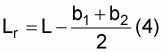
b = wooden beam width
Formula (5) gives the number of wooden beams to be placed over a calculated distance:
nB = n’F + 1 (5)
The length of the wooden beams is calculated to formula (6):
BL = w + 2a (6)
BL = length of wooden beamw = clear width of the room
(in straining direction of the beams)
a = bearing length
(a = at least 150 mm)
Why should the wooden beams have equal distances?
____________________________________________
Why should the wooden beams have equal distances?
____________________________________________
Why must the wooden beams have a distance of a least 20 mm from the wall?
____________________________________________
What does the formula nB = n’F + 1 say?
____________________________________________
Why must nF be rounded off to the next integer number?
____________________________________________
|
| ||||||||||||||||||||||||||||||||||||||||||||||||
6. Load on Wooden Beams
The wooden beams of one framing cannot be loaded by loads of any quantity.
Why can the wooden beams not be loaded by loads of any quantity?
____________________________________________
For the loading of such ceilings a continuous surface load is assumed. The basis in housing construction is a working load of 2.0 kN/m2.
Such load is reached in exceptional cases only. It would mean that about 48 persons would stay at the same time on a wooden beam ceiling of a room with an area of 16 m2 (about 0.75 kN/person).
When the wooden beam ceiling is loaded, the wooden beams deflect. Such deflection will always occur with loads but it must not exceed 1/300 of the span.
The uniformly distributed, allowable (safe) load on a wooden beam ceiling, with due consideration to the deflection of the wooden beams, is determined through the moment of inertia.
The table for cross sections of wooden beams shows sections for coniferous wood (NH) of grade II (Gk II) for clear widths of rooms (w) from 2.0 m to 5.0 m as well as for distances of wooden beams of 600 mm, 800 mm and 1000 mm.
The sections of the wooden beams refer to a total load (dead load and working load of the wooden beam ceiling) of 4.0 kN/m2.
Table 3: Table for cross sections of wooden beams
This table shows cross sections of wooden beams (NH, Gk II) for
a load of 4.0 kN/m2.
(dead load = = 2.0 kN/m2, working
load = 2.0 kN/m2)
The dead load of the wooden beam ceiling corresponds to that of a heat and sound-insulating ceiling.
|
Clear width of room |
Distances of wooden beams | ||
| |
600 mm |
800 mm |
1000 mm |
|
in mm w |
b/h in cm2 |
b/h in cm2 |
b/h in cm2 |
|
2000 |
6/12 |
8/12 |
10/12 |
|
2100 |
8/12 |
10/12 |
12/12 |
|
2200 |
8/12 |
10/12 |
10/14 |
|
2300 |
10/12 |
12/12 |
10/14 |
|
2400 |
12/12 |
8/14 |
12/14 |
|
2500 |
12/12 |
10/14 |
14/14 |
|
2600 |
10/14 |
10/14 |
14/14 |
|
2700 |
10/14 |
12/14 |
12/16 |
|
2800 |
12/14 |
12/14 |
12/16 |
|
2900 |
12/14 |
14/14 |
14/16 |
|
3000 |
14/14 |
10/16 |
16/16 |
|
3100 |
10/16 |
12/16 |
16/16 |
|
3200 |
12/16 |
14/16 |
14/18 |
|
3300 |
12/16 |
14/16 |
14/18 |
|
3400 |
14/16 |
16/16 |
16/18 |
|
3500 |
14/16 |
16/16 |
16/18 |
|
3600 |
16/16 |
14/18 |
18/18 |
|
3700 |
16/16 |
14/18 |
14/20 |
|
3800 |
14/18 |
16/18 |
16/20 |
|
3900 |
14/18 |
16/18 |
14/22 |
|
4000 |
16/18 |
18/18 |
14/22 |
|
4100 |
16/18 |
18/18 |
16/22 |
|
4200 |
12/20 |
14/20 |
16/22 |
|
4300 |
14/20 |
16/20 |
18/22 |
|
4400 |
14/20 |
18/20 |
18/22 |
|
4500 |
16/20 |
18/20 |
18/22 |
|
4600 |
16/20 |
20/20 |
20/22 |
|
4700 |
14/22 |
20/20 |
22/22 |
|
4800 |
14/22 |
16/22 |
18/24 |
|
4900 |
16/22 |
18/22 |
^0/24 |
|
5000 |
16/22 |
18/22 |
20/24 |
Coniferous wood (NH), such as spruce, pine wood grade II (Gk II) means:
- wood free from wood pest,- wood with knots having a diameter of less than 1/3 of the wood width but not exceeding 70 mm,
- the sum of all knot diameters over 150 mm wood length per area of cut must not exceed 2/3 of the wood width.
If the cross sections of wooden beams shown in the table are not in stock, other sections may be used.
Other cross sections, however, would mean to calculate them through the section modulus.
Assuming that wooden beams are mainly used with rectangular section, the small face is always used as bearing surface.
If the width of the beam shall be changed, the height of the beam must be changed, too.
The section modulus for wooden beam sections is calculated by means of the formula:
W = section modulus referred to the x axis
b = width of the wooden beam
h = height of the wooden beam
If the height of the beam shall remain unchanged, the formula is to be converted to give b as follows:

If the width of the beam shall remain unchanged, the formula is to be converted to give h as follows:

If the result is a decimal fraction, it is to be rounded off to the next greater size of wooden beams.
For example:
b = 13.4 cm - - - b = 14 cm
b = 14.1 cm - - - b = 16 cm
h = 21.5 cm - - - h = 22 cm
h = 20.5 cm - - - h = 22 cm
|
| ||||||||||||||||||||||||||||||||||||||||||||||||
7. The List of Timber
The wooden beams of one wooden beam framing must be ordered and supplied exactly to the wooden beam section and wooden beam length.
Why can the wooden beams not be ordered and supplied in m3?
____________________________________________
For better clearness of the order, a list of timber is used. (See Table 4)
Table 4: Example for a list of timber for the 2nd floor framing
|
No. |
Pos. |
Designation |
Cross section |
Individual |
m ace. to cross section | |||
| | | |
mm/mm |
length mm |
100 |
120 |
140 |
160 |
|
1 |
2 |
verge beam |
140/200 |
5400 | | |
10.80 | |
|
2 |
10 |
intermediate beam |
160/200 |
5400 | | | |
54.00 |
|
3 |
2 |
passing beam |
120/200 |
5400 | |
10.80 | |
|
|
4 |
2 |
tail beam |
160/200 |
2310 | | | |
4.62 |
|
5 |
2 |
beam trimming |
160/200 |
1600 | | | |
3.20 |
|
6 |
1 |
filling timber |
100/200 |
800 |
0.80 | | | |
|
Total length in m |
0.80 |
10.80 |
10.80 |
61.82 | ||||
| |
0.02 |
0.32 |
0.32 |
1.85 | ||||
|
Total length and waste |
0.82 |
11.12 |
11.12 |
63.82 | ||||
|
Volume in m3 |
0.02 |
0.27 |
0.32 |
2.04 | ||||
|
Total volume in m3 | |
2.65 | | | ||||
|
| ||||||||||||||||||||||||||||||||||||||||||||||||
8. The Wall Plate
Actually the wall plate is not a plate but a rectangular timber. The purpose of the wall plate is to accommodate the wooden beams of a framing, to ensure a uniform bearing height and to better distribute the bearing force over the bearing.
A rectangular timber with a cross section of b/h = 100/80 mm2 or 80/60 mm2 is used as wall plate.
Is the wide or small face of the rectangular timber used as bearing surface of the wall plate?
____________________________________________
In order to prevent axial or lateral displacement of the wooden beams, the beams are cogged in the wall plate or are secured by means of a pin connection.
The wall plate is mainly necessary in brickwork construction. On a 240 mm thick wall, the wall plate is to be mounted flush with the inner wall line.
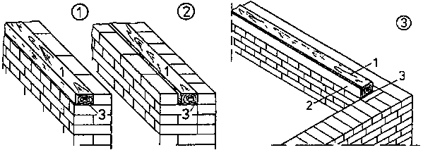
Figure 13
(1) wall plate mounted flush with the inner wall line
(2)
wall plate displaced to the centre of the wall
(3) wall plate mounted flush
with the inner wall line and provided with plaster base
1 wall plate, 2
plaster base (wood-wool board), 3 barrier layer under the wall plate
Why is the wall plate to be mounted flush with the wall line?
____________________________________________
On a 365 mm thick or thicker wall, the wall plate may be displaced towards the centre of the wall, i. e. it is to be displaced inwards as much as to leave enough room for the wall plate to be faced with a plaster base.
Why must the wall plate be faced with a plaster base?
____________________________________________
Sling fabric or Rabitz fabric may be used as plaster base for flush-mounted wall plates. A strip of woodwool wall board may be used as plaster base for non-flush wall plates.
|
| ||||||||||||||||||||||||||||||||||||||||||||||||
9. Flooring Sleepers
If a solid ceiling is to be provided with batten floor as top ceiling, flooring sleepers are required for fixing the battens.
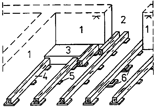
Figure 14
Flooring sleepers on solid ceiling
1 brickwork with metre mark, 2 door opening, 3 stove foundation, 4 flooring sleeper, 5 packing at the bottom (substructure), 6 barrier cardboard
The flooring sleepers take over the function of the wooden beams and are also placed according to the pitch size.
Why must the wooden beams or flooring sleepers be placed according to a calculated pitch size?
____________________________________________
The timbers used as flooring sleepers should be sound, peeled, parallel trimmed at two sides, preferably treated with wood preservative and have a height of at least 100 mm.
Figure 15
Cross sections of flooring sleepers
(1) square sleeper
(2) sleeper parallel cut at two sides,
symmetrical
(3) sleeper parallel cut at two sides, asymmetrical
The wide face of the flooring sleepers is to be used as bearing surface so as to ensure good and immovable bearing. This is of special importance if slag is to be placed between the flooring sleepers as sound and heat-insulating material.
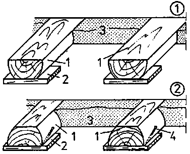
Figure 16
Functional position of flooring sleepers
(1) wrong position
(2) correct position
1 sleepers, 2 substructure (packing at bottom), 3 slag, 4 pin nail
What would happen to the flooring sleepers when the slag is placed and compacted, if this is not taken into account?
____________________________________________
The substructure (packing at the bottom) of the sleepers consists of hardwood wedges or other material.
The top surface of the sleepers is to be exactly levelled by means of a level board.
The substructure is to be secured against displacement by pins. A barrier layer (barrier cardboard) is to be placed between the solid ceiling and sleepers or wooden substructure, respectively.
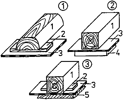
Figure 17
Substructure of flooring sleepers
(1) wooden packing
(2) stone-slab packing
(3) packing by
even bed of mortar
Why is a barrier layer to be placed?
____________________________________________
|
| ||||||||||||||||||||||||||||||||||||||||||||||||
10. Special Constructional Recommendations
Sound and heat insulation in ceilings
- If ceilings are to be provided with sound or heat insulation or both, the hollow space between verge (gable) beam and gable wall or between passing beam and partition wall, respectively, is to be filled with moisture-resistant material.- The gap between the jamb of flue and filling timber or beam trimming, respectively, is to be filled with non-flammable material.
- If mineral wool mats or textile fibre mats are used, they are to be fixed to the wooden beams by wooden strips.
- If insulating mats are to be joined, they must be overlapped sufficiently.
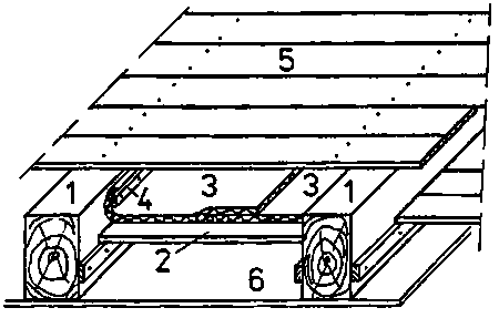
Figure 18
Wooden beam ceiling with heat insulation only
1 wooden beams, 2 dead floor (laggings), 3 heat-insulating mat, 4 wooden strip to fix the insulating mats, 5 flooring, 6 protection against trickling matter (particle board)
- If slag is used for footfall sound insulation, the slag is to be placed as high as to provide good supporting contact for the blind side of the floor battens.- Dry material only must be used for sound and heat insulation.
- If heat insulation is required for the outside wall, heat-insulating material is to be placed at the respective crosgrained end of the wooden beam.
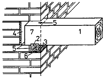
Figure 19
Heat insulation in the area of the beam head
1 wooden beam, 2 wall plate, 3 plaster base, 4 heat-insulating material, 5 air gap, 6 barrier layer, 7 beam head
Connection between brickwork and wood
- All wooden parts, which are fixed in the wall, must be protected against the moisture in the brickwork.- The wall plate is fixed in the wall “dry”, i. e. the bricks are laid without mortar in a distance of 1 cm from the wall plate.
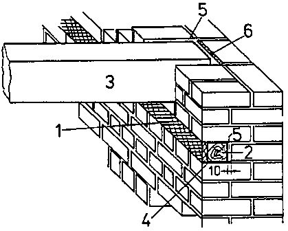
Figure 20
Wall plate fixed in the wall
1 plaster base, 2 wall plate (fixed dry), 3 wooden
beam,
4 barrier layer, 5 air gap, 6 heat-insulating material
- An air gap of about 1 cm is to be left around the head of the beam.
- At the face end of the head of the beam, an air gap of 2 cm is to be left (See Fig. 19).
- On the wall plate and on the head of the beam, the bricks are to be laid without mortar (dry).
- The air gap around the head of the beam must not be filled with plaster mortar.
Tieing of the wooden beams
Ceilings must stiffen the building or room.
For this purpose the wooden beams are tied to the outer walls.
In the longitudinal walls (walls accomodating the wooden beams) every third wooden beam is provided with a beam tie.
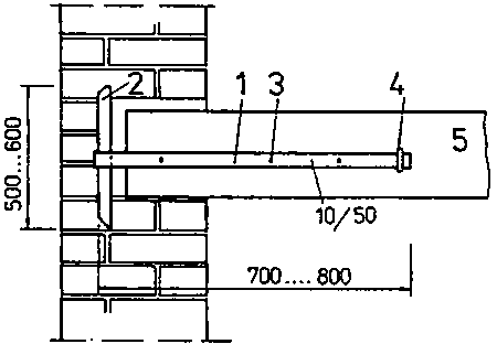
Figure 21
Beam tie as head tie
1 beam tie, 2 cotter pin, 3 screw or forged nail, 4 cramp, 5 wooden beam
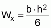
The gable walls are secured by gable ties.
Gable ties must extend over at least three wooden beams.
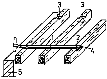
Figure 22
Beam tie as gable tie
1 gable tie, 2 screw or forged nail, 3 recess for gable tie, 4 cramp, 5 brickwork

Figure 23
Distribution of gable ties
1 gable tie, 2 screw, 3 recess, 4 head tie, w clear width of the room
They are arranged in the third points of the wooden beams.
The inner edge of the cotter pin should have a distance of 240 mm to the inner edge of the wall.
The gable ties should be placed in a recess in the wooden beams. Screws or forged nails are to be used for fixing the beam ties or gable ties!
Additionally they are to be secured by cramps to be placed before the upward edge-bend.