 |
| ||||||||||||||||||||||||||||||||||||||||
|
| ||||||||||||||||||||||||||||||||||||||||
Institut f�r berufliche Entwicklung e.V.
Berlin
Original title:
Herstellen von Zwischenw�nden
Author: Rolf Becher
First Edition © IBE
Institut f�r berufliche Entwicklung e.V.
Parkstra�e
21/23
13187 Berlin
Order No.: 93-35-3605/2
|
| ||||||||||||||||||||||||||||||||||||||||
1. Necessity of Partition Walls
Partition walls are necessary wherever big rooms shall be partitioned into smaller ones. The partitioning of rooms into smaller rooms depends on the use of the rooms. For example, the goods to be stored may dictate the size of the rooms and the necessity for partitioning of rooms.
But the use of a cold roof attic for housing purposes also necessitates partitioning of rooms. The use of rooms calls for specific constructional requirements to be met by the partition wall.

Figure 1
Partition wall without sound insulation
1 head runner, 2 foot runner, 3 wall post, 4 joint post, 5 post, 6 wall covering, 7 length of surface covering material

Figure 2
Partition wall with sound insulation
1 head runner, 2 foot runner, 3 wall post, 4 joint post, 5 post, 6 wall covering, 7 sound-insulating mat, 8 wooden strip
So, the design of a partition wall for housing purposes differs from that for storing purposes of temperature-insensitive or temperature-sensitive goods.
In any case, partition walls for housing purposes call for sound insulation (sound-proofing). Sometimes heat insulation will also be required. The surface finish of the partition walls also depends on the use of the room.
Rooms intended for housing purposes call for partition walls with a surface of aesthetic appearance.
This is not required when the room shall be used for storing purposes.
|
| ||||||||||||||||||||||||||||||||||||||||
2. Limitation of Rooms
The partition of existing rooms and the limitation of rooms to be built by the erection of partition walls are governed by various criteria:
The rooms must be accessible.
- Existing doors are to be used.
- Existing walls can be broken through for door openings.
- Doors can also be built into partition walls.
Figure 3
1 room to be partitioned, 2 existing door, 3 partition wall to be built, 4 building-in range of partition wall
Figure 4
1 partitioned rooms, 2 existing door, 3 partition wall built in, 4 door to be made
The rooms must have ventilation facilities. Existing windows can be fixed points for partitioning of rooms.
King posts and angle braces in attics are to be taken into account for limitation of rooms. The floor space of the rooms to be built is limited by the roof structure
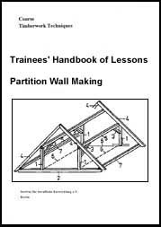
Figure 5
1 king post, 2 attic beam, 3 angle brace, 4 roof rafter, 5 trussed purlin, 6 room limitation by king posts, 7 inferior purlin
Trussed purlins in attics are fixed points for height limitation.
They limit the height of the rooms to be built.
Figure 6
1 attic beam, 2 king post, 3 angle brace, 4 trussed purlin, 5 height limitation by trussed purlin
The location of the wooden beams of a wooden beam ceiling may have influence on the floor space dimensions of the rooms to be built.
The location and straining direction of wooden beams can be concluded from uncovered nailing.
Figure 7
1 wooden beam, 2 straining direction of boarding, 3 foot runner, 4 head runner, 5 post, 6 uncovered nailing of boarding
Partition walls must not be erected between the wooden beams of boarded floors.
If this cannot be avoided because of the distribution of rooms, the runner must be statically verified and be supported by the walls bearing the wooden beams.

Figure 8
1 wooden beam, 1 straining direction of boarding, 3 foot runner, 4 head runner, 5 post, 6 uncovered nailing of boarding
Partition walls on wooden beam ceilings must be designed as light-weight walls. The light-weight wall comprises the wooden framework with surface covering (see Fig. 1 and Fig. 2).
Why do king posts of a roof structure limit the floor space of the rooms to be built?
______________________________________
What is the effect of trussed purlins?
______________________________________
Partition walls must not be erected between the wooden beams of boarded floors. Give reasons for this statement!
______________________________________
|
| ||||||||||||||||||||||||||||||||||||||||
3. Surface Covering
The material of surface coverings depends on the use of the rooms.
The material applied for rooms to be used as living rooms, for example, should have a surface with no open pores or which can be subsequently refined (faced).
Suitable materials for surface coverings are:
- Plaster cardboard slabsThe surface is finished.
- Hardboard slabs
The surface is smooth and finished.
- Particle board slabs
The surface can be puttied.
- Wood-wool slabs
The surface can be faced by plastering.
The surface covering should ensure a pleasant atmosphere to live in.
A surface covering of plywood or planed boards cannot be recommended for all walls of a room but such covering on one of the four walls is conducive to a cosy atmosphere to live in.
For rooms intended for storing purposes, the sensitivity of the materials to be stored is to be considered for the wall covering which may be made of:
- plywood,
- solid wood (planed or unplaned),
- wood-wool slabs (plastered or unplastered),
- particle board slabs (puttied or unputtied).
|
| ||||||||||||||||||||||||||||||||||||||||
4. Framework of the Partition Wall
The framework of the partition wall consists of the two runners with the mortised posts and their stiffening transoms. (See Fig. 12)
The width and thickness (d) of the runners and stiffening transoms must be suited to the posts.

Figure 9
1 foot runner, 2 post, 3 stiffening transom
Why must the width of the runners and transoms be suited to the posts?
______________________________________
The runner height (s) and the height of the stiffening transoms should be 50 mm.
The posts must be sufficiently dimensioned to resist any acting horizontal forces and existing vibrations.
The dimensions of the posts depend on the room height and are shown in table 1.
Table 1: Dimensions of the posts
|
Room height |
Wxreq |
b |
d |
b |
d |
b |
d |
b |
d |
b |
d |
b |
d |
| | |
all sizes in mm | |||||||||||
|
1750 |
33 |
25 |
85 |
30 |
80 |
35 |
75 |
40 |
70 |
45 |
65 |
50 |
60 |
|
2000 |
38 |
30 |
87 |
35 |
81 |
40 |
75 |
45 |
72 |
50 |
67 |
55 |
64 |
|
2250 |
43 |
40 |
80 |
45 |
76 |
50 |
72 |
55 |
68 |
60 |
66 |
65 |
63 |
|
2500 |
47 |
50 |
75 |
55 |
71 |
60 |
68 |
65 |
65 |
70 |
63 |
75 |
61 |
|
2750 |
52 |
50 |
78 |
55 |
75 |
60 |
72 |
65 |
69 |
70 |
66 |
75 |
64 |
|
3000 |
57 |
60 |
76 |
65 |
72 |
70 |
69 |
75 |
67 |
80 |
65 |
85 |
63 |
|
3250 |
61 |
65 |
75 |
70 |
72 |
75 |
69 |
80 |
67 |
85 |
65 |
90 |
63 |
|
3500 |
66 |
65 |
78 |
70 |
75 |
75 |
72 |
80 |
70 |
85 |
68 |
90 |
66 |
|
3750 |
71 |
70 |
78 |
75 |
75 |
80 |
73 |
85 |
71 |
90 |
69 |
95 |
67 |
|
4000 |
74 |
75 |
77 |
80 |
75 |
85 |
73 |
90 |
71 |
95 |
69 |
100 |
67 |
Dimensions refer to a load of 750 N in the centre of the room height

Figure
Horizontal forces may be produced in the event of accidental pushes against the wall or of collisions by objects falling off. The distances of the joint posts depend on whether the material used for the surface covering is directly fixed to the post or to additional rafters.

Figure 10
Fixing of the surface covering material
(1) surface covering material directly fixed to the post
(2)
surface covering material fixed to additional rafters
1 foot runner, 2
post, 3 covering material, 4 fixing means, 5 additional rafters
If the surface covering material is directly fixed to the posts, the lengths of the material dictate the distances of the joint posts. With partition walls for rooms intended for housing purposes and where the joints are not subjected to further working, the distances of the joint posts should be symmetrical.
In such case the length of the covering material is to be shortened.

Figure 11
Symmetrical arrangement of the posts
1 wall post, 2 joint post, 3 post, 4 surface covering material, 3 shortening of surface covering material, 6 section
If the surface covering material is fixed to additional rafters, the distances of the joint posts do not matter. The symmetry of the covering can be ensured by the material used.
Irrespective of the dimensions shown in table 1, the joint posts should have a width of at least 80 mm.
Why should the joint posts have a width of at least 80 mm?
______________________________________
If possible, the posts between the joint posts should have equal distances so as to subject each post to equal load. Equidistant arrangement of the posts between the joint posts is all the more important if the fixing means (screws, nails) for the surface covering remain visible, otherwise the visible nail or wood screw heads would disturb the appearance of the surface covering.
The distance of the posts between the joint posts depends on the stability of the covering material. This also applies to the distance of the additional rafters.
The distance of the stiffening transoms should not exceed 1250 mm. If the height of partition walls requires several stiffening transoms, they should have equal distances.
If a door is necessary in the partition wall, it is to be included irrespective of the distribution of the posts.
For this purpose, a trimming is to be made to include the door post and door fixing post. The trimming also serves as door lintel transom.

Figure 12
Inclusion of the door in the partition wall
1 foot runner, 2 wall post, 3 head runner, 4 door post, 5 door fixing post, 6 door lintel transom, 7 stiffening transom, 8 post, 9 tail post
It may also be necessary to arrange a partition wall at right angles to the wooden beam framing.

Figure 13
1 wooden beam, 2 foot runner, 3 post
If partition walls meet at right angles to each other, a corner post and an additional post are necessary in the continuous partition wall.

Figure 14
1 foot runner, 2 head runner, 3 wall post, 4 joint post, 5 post, 6 additional post, 7 surface covering
The additional post is not taken into account when calculating the pitch size. It serves for holding the surface covering and must be offset accordingly. The corner posts and the additional post have the same dimensions as the corner posts.
|
| ||||||||||||||||||||||||||||||||||||||||
5. Calculation of the Pitch Size
Before you can start to calculate the pitch size, you have to check the perpendicularity of the walls, the horizontal of the ceiling and of the floor, the squareness of ceiling and wall and of floor and wall.
Any deviations are to be considered in the calculation of the pitch size.
For example, the distance between the wall post and the following or preceding post may be different at the head runner or foot runner.
The post at the right hand of the left wall post and the post at the left hand of the right wall post must be perpendicular.
The joint post should have a width (b) of at least 80 mm to provide a sufficient bearing surface for the surface covering material.
The width of the joint post is not taken into account when calculating the pitch size (distance of the posts from jointing to jointing). The difference of the joint post width is determined when scribing on the runners.
Figure 15
1 runner, 2 pitch size, 3 post width, 4 compensated joint post width, 5 jointing mark
The calculation of the pitch size is based on a symmetrical arrangement of the framework of the partition wall and is done as follows:
In the event of one joint post between the wall posts or between the wall post and the corner post:
- Read the dimensions for the posts to be used to know the width (b) of the post for the calculation!(If posts of other width are used, take that width for the calculation).
- Divide the total length of the partition wall (G1) by the length of the covering material to be used (M1)!
The result gives the number of sections (nT).
Formula:
If nT is a decimal fraction, round up to the next integer number!Subindex “a” is then added to nT (nTa)!
- Divide the total length (G1) by the rounded-up number of sections (nTa)!The result gives the length of one section (Lt).
Formula:

- Subtract half the width (b/2) of the post to be used from the length of the section (Lt) and divide by the admissible distance of the post (aadm)!The result gives the number of divisions of one section (nF).
Formula:

If nF is a decimal fraction, round up to the next integer number!
Subindex “a” is then added to nF (nFa)
- Divide the length Lt - b/2 by the rounded-up number of divisions (nFa)!
The result gives the distance of the posts (a) between the wall post and joint post or wall post and corner post.
Formula:

If “a” includes tenths of a millimetre, they are compensated when scribing!
Several joint posts in the framework of the partition wall
If several joint posts are required between the wall posts or between the wall and corner posts, then do not subtract half the width of the post from the section as explained in step 5 above!
Formula:

Example 1:
It is assumed that the partition wall to be built has a total length of 4000 mm and the height of the room is 2750 mm. The length of the covering material is 2200 mm. The distance of the posts must not exceed 500 mm!
What pitch size is to be scribed on the runners?
Solution:
1. Reading of the dimensions of the posts in table 1.
b = 50 mm, d = 78 mm or b = 55 mm, d = 75 mm or
b = 60 mm, d = 72 mm or b = 65 mm, d = 69 mm or
b = 70 mm, d = 63 mm or b = 75 mm, d = 61 mmDecision in favour of b = 50 mm, d = 78 mm.
2. Calculation of the number of sections.
Requ.: nT 
Known: G1 = 4000 mm
M1 = 2200 mm
nTa = 2
3. Calculation of the number of sections.
Requ.: Lt 
Known: G1 = 4000 mm
nTa = 2Lt = (4000 mm)/2
Lt = 2000 mm
4. Calculation of the number of divisions: “Two sections” means one joint post!
Requ.: nF 
Known: Lt = 2000 mm
b =50 mmaadm = 500 mm

nFa = 4
5. Calculation of the pitch size:
Requ.: a 
Known: Lt = 2000 mm
b = 50 mmnFa = 4

a = 493.75 mm
Result:
The pitch size to be scribed on the runners for the posts to be mortised amounts to 493.75 mm from jointing to jointing.
When scribing the pitch size on the runners, the folding rule is to be placed so as to permit continuous scribing:
493.75 (+493.75 =) 987.5 (+493.75 =) 1481.25 (+493.75 =) 1975
Figure 16
Example 2:
It is assumed that the partition wall to be built has a total length of 7860 mm. The room height is 2500 mm.
The distance between the posts must not exceed 400 mm.
The covering material has a length of 2000 mm.
What pitch sizes are to be scribed on the runners?
Solution:
1. Reading of the dimensions of the posts in table 1:
Selected: b = 60 mm, d = 68 mm
2. Calculation of the number of sections:
Requ.: nT
Known: G1 = 7860 mm
M1 = 2000 mm
nTa = 4
3. Calculation of the section length:
Requ.: Lt
Known: G1 = 7860 mm
nTa = 4
Lt = (7860 mm)/4
Lt = 1965 mm
4. Calculation of the number of division:
Requ.: nF 
Known: Lt = 1965 mm
b =60 mm
aadm = 400 mm
nFa = 5
5. Calculation of the pitch sizes:
For section A - D
Requ.: a
Known: Lt = 1965 mm
b = 60 mm
nFa = 5
a = 387 mm
For section B - C
Requ.: a 
Known: Lt = 1965 mm
nFa = 5

a = 393 mm

Figure
17
|
| ||||||||||||||||||||||||||||||||||||||||
6. Scribing of the Structural Components
The present booklet only deals with scribing of the structural components and not with working of the necessary wood joints.
Scribing of the runners
When the pitch size for the sections has been calculated, the head and foot runners are to be inspected and the joining sides to be marked with a jointing mark.
For more efficient scribing, the runners are to be put on two one-ell trestles.
The runners are to be put on the trestles so as to ensure that the joining sides of the head runner and foot runner are facing each other, that the runners lie closely together and parallel to each other and that their left ends are flush!
Figure 18
Runners put on the trestles
1 closely together, 2 parallel to each other, 3 about flush at the left end, 4 jointing mark, 5 one-ell trestles, 6 saddle timber (of trestle)
Why must the joining sides face each other?
______________________________________
By putting the runners to one another, they can be scribed together to ensure parallelism of the posts to be erected.
The following steps are recommended for scribing of the runners:
1. Scribe the shortening at the left ends and mark with section mark!
Go to the right only as far as necessary to produce a right-angle section.2. Scribe the pitch size and mark the joining side!
The pitch size of each section is to be scribed cumulatively.1)
See Fig. 16)
1) cumulative = increasing steadily in amount by one addition after another
3. Measure-in and scribe the post width!
A template is to be used having the width of the posts.
(template = master board)4. Measure-in and scribe the joint post width!
The difference between post and joint post is to be equally distributed at both sides.
(See Fig. 17)5. Scribe the tenon parapet and mortise width!
A commercial or self-made marking gauge is to be used for this purpose.
Do not adjust the marking gauge! It is to be used again for marking the posts and stiffening transoms!6. Scribe the longitudinal half joints at the right ends of the runners!
Think of the fact that the upper half-joint accommodates the tenon.
(This steps may not be required in any case).
Scribing of the posts
Before the posts can be scribed, the room height and runner height (s) must be known. The runner height should be between 40 mm and 50 mm.
To determine the post length, deduct two runner heights (s) from the room height and add two tenon lengths!
A tenon length of 20 mm is sufficient.
After determining the length of the posts, inspect the posts, decide on the joining side and mark with jointing mark. The joining side should always be a side guaranteeing the evenness of the partition wall to be built.
For scribing of the posts, no more than five posts should be put on two one-ell trestles. It is important to put the posts on the trestles so that their left ends are about flush, parallel to each other and closely together and with their joining sides on top.
Figure 19
1 about flush, 2 jointing mark on top, 3 put closely together, 4 parallel to each other, 5 saddle timber
Proceed with scribing as follows:
1. Scribe the shortening at the left end on the front edge of the post at the front, place the square with the long leg and scribe the section line over all posts put on the trestles.
(Go to the right only as far as necessary to produce a right-angle section on all posts).2. Measure-in the tenon length, the post length and the second tenon length at the front edge of the post at the front, startening from the left section line towards the right.
(Just mark the measured sizes).3. Place the square with the leg at the post at the last right-hand marking, scribe the section line over all posts put on the trestles and mark it.
4. Check the size between the sections.
(If the sizes are not identical, find the reason and make the necessary corrections).5. Scribe over all posts put on the trestles all marking made at the front edge of the post placed at the front.
(Make sure that the long leg of the square is placed correctly).6. Scribe the tenon parapets.
For this purpose, the posts are to be moved apart to enable the marking gauge to be handled between them.
Starting from the joining side, the front parapet is scribed first and then the rear parapet is scribed at the left ends of the posts in the same manner.
The work flow is shown in Fig. 20 and Fig. 21.
Figure 20
Figure 21
If more posts than those placed on the trestles are to be scribed, the post placed at the front is to be used as template!
Why is the post at the front to be used as template?
______________________________________
Scribing of the stiffening transoms
Scribing of the stiffening transoms is to be done in the same manner as scribing of the posts but with different length sizes. Tenon lengths of 15 mm are sufficient so as not to weaken the cross section of the posts excessively.
|
| ||||||||||||||||||||||||||||||||||||||||
7. Erection of the Partition Wall
Before the partition wall is erected, the alignment is drawn on the floor. For this purpose, a line is stretched and the alignment marked at about 1000 mm intervals. The marked line is marked with marking-out mark (bird’s-mouth). Since the tenons of the posts are accommodated in the mortises of the foot and head runners and the stiffening transoms are also provided with tenons, the whole partition wall is to be assembled before it is erected.
Assembling is done either flat on the floor or in inclined position supported by an auxiliary structure.
The foot runner is to be placed in parallel with and as closely as possible to the alignment. The aligned partition wall is to be moved as a whole.
When the partition wall has been erected according to the scribed markings, it is to be secured against falling off. This can be achieved by wedges to be driven in between the wall post and the wall.
When the partition wall has been secured against falling off, holes are to be bored into the foot and head runners for anchoring them.
The diameter of the holes depends on the shank diameter of the hexagon-head wood screws used for anchoring.
The distance of the holes should not exceed 1000 mm.
When placing the hexagon-head wood screws, the washers must not be forgotten.
When the screw is tightened by means of an open-jawed or ring wrench, it is to be made sure that the washer penetrates the wood of the runner together with the screw head.
|
| ||||||||||||||||||||||||||||||||||||||||
8. Constructional Recommendations
- If existing walls, which the wall post is to be placed to, are not perpendicular or are bulging, the wall post may be displaced inwards. The difference of such displacement is to be taken into account when calculating the pitch size.- If partition walls are erected between two wall posts, the sizes measured for the length of the foot and head runners should be used for the calculation of the pitch size about 20 mm smaller to avoid pressing of the framework of the wall when erecting it.
- If sound insulation is required for the partition wall to be built, all joints between the wall and the wall posts, between the ceiling and the head runner, as well as between the floor and the foot runner are to be sealed with sound-insulating material.
- Sound bridges must be avoided, otherwise it would mean a waste of the finance and material employed.
- If doors are to be included in the partition wall to be built, the door posts, door fixing posts, door lintel transom and tail posts with the respective sizes are to be scribed in the same manner as the posts (see page 17 hereof).
- If partition walls with corner posts are required, the meeting of the walls and the existing building clearance are decisive for the wall to be erected first.
- If partition walls are erected at right angles to the wooden beam ceiling, the distances of the holes for fixing the runners depend on the distances of the wooden beams.
- If foot runners are interrupted by door opening, the foot runner is to be cut only at the place of mounting so that it can be used, if in alignment, for scribing on the floor (of alignment)!
- For stabilizing the door opening on the floor, the foot runner can be held by a metal square to be additionally mounted. The leg of the square to be screwed to the floor must not be longer than the thickness of jamb lining to be provided! Long nails (4.2/100) may be used for fixing the leg of the square to the cross-grained wood of the runner.
- If partition walls are erected between solid ceilings, the runners are to be placed according to the alignment lines and the holes in the runners for fixing to ceiling and floor are to be scribed. The size is to be measured from the joining side of the runner to the centre of the hole on that side of the runner which will contact the floor or the ceiling when the partition wall is erected. This is necessary to enable dowels to be inserted or holes for straddling dowels to be bored and dowels to be driven in for fixing the runners prior to the erection.