Generation, Distribution, Use of Electric Current - Basic vocational knowledge (Institut f�r Berufliche Entwicklung, 141 p.)
4. Power transmission and distribution in power supply systems
(introduction...)
4.1. Types of networks
4.2. International networks
4.3. Common voltage levels in the flow of electric energy
4.3.1. The importance of the voltage
4.3.2. Voltage levels of the elec-trotechnical networks
4.4. The importance of the electric current as dimensioning criterion for all transmission elements
(introduction...)
4.4.1. Operating current
4.4.2. Short-circuit current
4.4.3. Environment
4.5. Common technical terms in the field of transmission and distribution
4.6. Lines and cables as transmission and distribution elements
4.6.1. Basic terms
4.6.2. Lines for heavy-current installations
4.6.3. Power cables
4.7. Switching and distributing plants and accessories for the transmission and distribution of electric energy
4.7.1. Switching and distributing plants
4.7.2. Switches
4.7.3. Accessories
4.7.4. Insulating material (insulators)
4.8. Laying of lines and cables
4.8.1. General
4.8.2. Laying of lines
4.8.3. Laying of cables
4.8.4. Electric connections
Generation, Distribution, Use of Electric Current - Basic vocational knowledge (Institut f�r Berufliche Entwicklung, 141 p.)
4. Power transmission and distribution in power supply systems
Electric power system
The whole of electrotechnical installations and networks
including all necessary additional devices for the generation, transmission and
use of electric power within one regional unit,
Electrotechnical installation (or plant)
The whole of equipment required for proper functioning of the
complete technological unit.
Electrotechnical network (or electric mains)
A system of interconnected electric lines of the same rated
voltage for the transmission and distribution of electric
power.
4.1. Types of networks
Supergrids (extra-high voltage systems) (transmission
function) for power supply to larger areas with transmission voltages of 110
kV, 220 kV and 380 kV.
Medium-voltage systems (distribution function) for
power supply to smaller areas (towns, parts of towns, industrial plants, etc.)
with transmission voltages of 1 to 30 kV.
Low-voltage systems (supply function) for power supply to
the majority of consumers (electric household appliances and motors of low and
medium capacity) with transmission voltages of up to 1 kV.
Open systems have a single feeding point.
Closed systems have two feeding points which makes
the network more fail-safe.
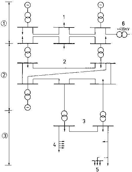
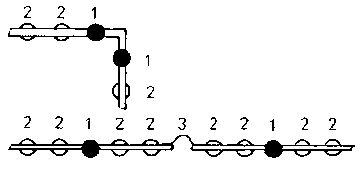
Figure 7. Various types of networks
as integral parts of the electric power transmission system - (1) supergrids
(extra-high voltage systems (2) medium-voltage system (3) low-voltage systems -
1 mesh-operated network, 2 medium-voltage ring-operated network, 3 low-voltage
distribution network (closed), 4 open network (multiple lump-loading), 5 star
network, 6 feeding
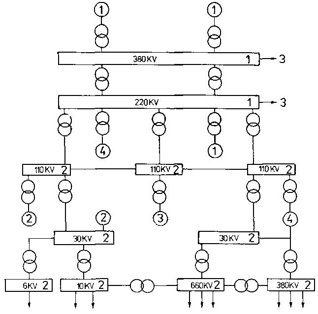
Figure 8. Example of interconnected
national networks - 1 transmission levels, 2 distribution levels, 3
international networks, - (1) power station, (2) heat-generating station, (3)
industrial power station, (4) pumped storage power station
Table 2 Open and closed systems (networks)
Type and circuit
Advantages and disadvantages
Examples of application
Open systems with
end-loaded lines
simple circuit, clear arrangement, very simple protective
system, very easy planning, good utilization, low costs, poor operational
reliability, poor voltage maintenance, high losses
small industrial plants and local networks of small extent
multiple lump-loaded lines
branched lump-loaded lines
lighting installations
Closed systems with
lines with double feeding
simple circuit
local networks for long-distance settlements, extended factory
halls
Closed system of
ring layout
clear arrangement
factory plants, medium-voltage distribution networks,
higher-level supergrids
star layout
better voltage maintenance, less losses, easy planning, better
operational reliability, poor utilization, acceptable costs, sophisticated
protective system
low-voltage distribution networks in big industrial plants
meshed layout
very good operational reliability, very good voltage
maintenance, low losses, very good utilization, less simple circuit, less clear
arrangement, very sophisticated protective system, less easy planning,
acceptable costs
local networks for bigger and large towns, low-voltage networks
for big companies
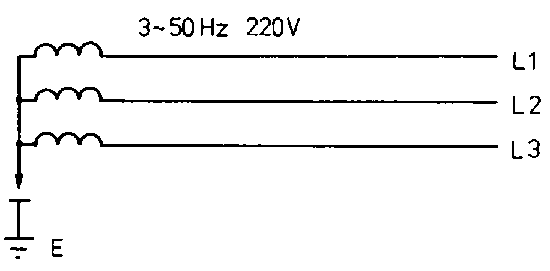
4.2. International networks
The designation of networks and conductors is internationally
coded to IEC 445.
The code letters used have the following meaning:
T terre (French) (earth) I insulation N
neutral wire C combined S separated P protection E
earth
TN-networks
Networks where one point of the network, i.e. one point of the
service circuit, is directly earthed (T) and the casings of the equipment or
installations are electrically connected with such point through a protective
conductor (N). They apply the protective measures of connection to neutral or
protective earthing with fault current return through metallic conductors (water
pipes, cable sheathings).
- TN-C-network PEN protective conductor with function of
neutral wire.
Figure 9. TN-C-network
- TN-S-network PE protective conductor carrying no operating
current.
Figure 10. TN-S-network
- TN-C-S-network PE protective conductor carrying no
operating current.
Figure 11. TN-C-S-network
TT-networks
Networks where one point of the network is directly earthed (1)
and the casings of the equipment or installations, irrespective of the existence
of any neutral wire, are connected with earth leads which are not electrically
connected to the earthed network point (T). Such networks, which are
internationally called TT-networks, apply protective earthing (single earthing)
using FI or FU protective circuits.
TT-network
Figure 12. TT-network
IT-networks
Networks where no point of the network is directly earthed (I)
but the casings of the equipment or installations are directly earthed (T). Such
networks apply the protective conductor system, protective earthing, FI and FU
protective circuits.
IT-network
Figure 13.
IT-network
4.3. Common voltage levels in the flow of electric energy
4.3.1. The importance of the voltage
The amount of voltage is decisive for the thickness of the
insulation material (wire insulation) or the size of the distance of active
conductors between each other and the earth. Economically this means the use of
expensive or less expensive insulation material and, with respect to overhead
lines, additionally occupation of ecologically important land. High-voltage
overhead lines also involve overhead construction problems. Depending on the
climatic zones, loads due to wind and ice, for example, are material-intensive
design
factors.
4.3.2. Voltage levels of the elec-trotechnical networks
The variety of the individual levels shall be demonstrated by
means of an example of an installation
Figure 14. Example of possible
voltage levels - 1 generator, 2 generator transformer, 3 substation transformer,
4 distribution transformer, 5 consumers, 6 voltages in kV
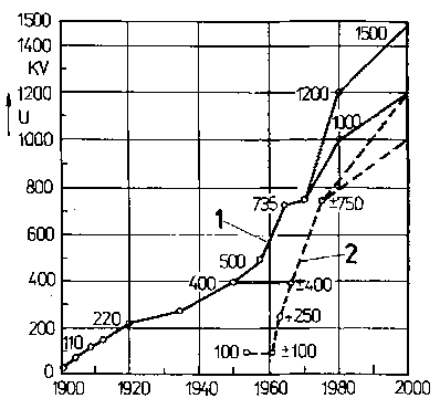
To enable efficient transmission of high powers over large
distance, the transmission voltages have become higher and higher in the course
of technological development.
Figure 15. Development of
transmission voltages worldwide - 1 high-voltage three-phase transmission, 2
high-voltage D.C.
transmission
4.4. The importance of the electric current as dimensioning criterion for all transmission elements
Having dealt with the effects of the voltage on the physical
dimensions of all electrotechnical transmission elements, we now consider the
effects of the electric current:
There are three objective factors of influence on the
dimensioning.
4.4.1. Operating current
The operating current is important for normal operation which
may be of continuous, short-time or intermittent type.
Continuous operation
Continuous operation means uninterrupted loading of all
transmission elements by current of almost constant intensity which, depending
on the current density, results in heating of the active conductors. That means
that all materials and auxiliary materials (insulation) as well as components,
which are in direct contact with the active conductor, absorb heat. The
consequences are expansion and aging effects on busbars, metal-clad cables, wire
insulations etc.
Short-time operation/intermittent operation
Short-time operation/intermittent operation mean that, after
periods of heating, all transmission elements undergo periods of cooling. This
may be aimed at maximum thermal peak-load on the one hand or at thermal load
below the limit load on the other hand. It depends on the components to be
used.
4.4.2. Short-circuit current
Faults normally involve extreme loads for all components,
depending on the design of the installation in terms of protection:
- Instantaneous short-circuit current
The so-called instantaneous or asymmetric short-circuit current
involves high electrodynamic loads for the installation parts immediately on its
occurence. The intensive magnetic fields generated as a consequence of such
current can physically destroy busbar installations, current transformer heads
(insulator-type transformer), switching devices etc. Conductor elements of
overhead lines may also be affected.
- Sustained short-circuit current
The sustained short-circuit current occuring after the
instantaneous short-circuit current has several times the intensity of the
operating current and, with a time lag after the short- circuit, results in
heavy or extreme heating of all components in the fault circuit. Mostly such
current destroys the installation parts unless this is prevented by adequate
protective
measures.
4.4.3. Environment
The thermal effects of the environment are important for the
dimensioning of the installation with respect to the cross sections of the
transmission elements and to the protective elements to be used. High ambient
temperatures physically call for larger cross sections and low ambient
temperatures permit smaller cross sections than normally specified for the
operating current. Mutual heating is taken into account in installation
engineering by providing for adequate distances of busbars, stranded conductors,
lines and cables between each other and between components and for air
circulation.
4.5. Common technical terms in the field of transmission and distribution
Outdoor plant/installation Installation exposed to
weather conditions without protection (see outdoor).
Open-type plant/installation Installation with
equipment not fully protected against accidental contact.
Outdoor(s) Limited area in the open air featuring the
same temperature and air humidity according to the local climate.
Assembly unit A combination of several components or
devices forming a functional unit.
Component A single part that can only work in
connection with other components.
Subassembly/module Locally combined group of
components which can function independently. Subassembly (in the context of a
project) is a self-contained part of a plant/installation as defined from
shipping and installation aspects.
Modular component/module A component which, because of
its specific modular design, can be assembled with other similar modular
components into a consistent whole.
(Component) part A constructionally and electrically
self-contained member of a part of an installation.
Enclosed Equipment and plants/installations which are
protected against environmental influences.
Protected outdoor installation/plant Outdoor
installation which is protected against rainfall up to an angle of incidence of
30 degrees to the perpendicular.
Main distribution (system) First distribution system
after power feeding.
Information unit The information unit of an
installation or section or part of an installation comprises its locally
functionally combined equipment for the generation, transmission, processing and
reception of information, even though this is implemented according to the rules
of heavy-current engineering.
Indoor installation/plant Installation inside rooms or
buildings.
Indoor(s) Room in buildings which is free from effects
of weather conditions
Mesh network Closed network system consisting of
crossing lines which are interconnected and fused at the crossing points. The
crossing points are called “nodal points”, the closed sections between
the nodal points a “mesh” and each part of the line “mesh
line”.
Nodal point of a network A point in the electric
energy distribution system where more than two circuits (lines) can be
interconnected.
Potential equalization Electrically conductive
connection between electrically inactive parts, such as water, gas and heater
pipes, steel structures, metallic cable sheathings, foundation earth leads and
protective conductors. This measure prevents a potential difference (voltage)
between such parts.
Figure 16. Example of central
potential equalization - 1 foundation earthing electrode, 2 heating tube system,
3 drinking water pipe, 4 gas distribution pipe, 5 house connection box, 6
customer’s meter. 7 potential equalization line (connection point
optional), 8 potential equalization bar (if necessary), 9 water meter
(conductively bridged, if the meter is built into a metallic pipe system), 10
structural design
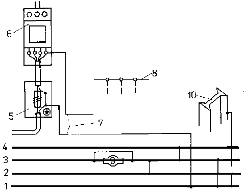
Primary system
It serves the purpose of directly distributing the electric
energy and includes all components directly involved in the transmission of
electric energy.
(Main) busbar A conductor - bar or rope - to which
several conductors or lines are connected.
Busbar section A portion of busbars or busbar
systems. Each section comprises only one part of the switchboard sections.
Busbar system Busbars with connected switchboard
sections.
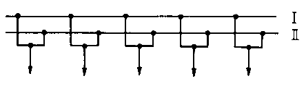
Figure 17. Double busbar system - I
system 1, II system 2
Busbar coupling Conductive connection between busbar
sections.
Figure 18. Longitudinal busbar
coupling - I, II, III busbar sections
Switching plant
Distribution system with switching devices which make it
possible to electrically connect and disconnect the outgoing main lines
with/from the busbar.
Switchboard section Local combination of the elements
belonging to one branch.
Secondary system It includes all facilities which are
necessary for the protection, control, monitoring, measuring and metering but
are not directly involved in the transmission of electric energy,
Station Room or part of a building housing one or more
electrotechnical installations or parts of installations and their service
facilities for the purpose of distribution and conversion of electric energy.
Conversion Change of the nominal value of physical
quantities which are characteristic of the form of electric energy. Conversion
includes transformation, frequency changing, rectification and inversion.
Subsidiary distributing system Distribution system
following the main distribution system.
Distribution plant Electrotechnical installation
including accessories, such as actuators, transformers, measuring devices etc.,
the main purpose of which is to distribute electric energy to several outgoing
lines.
Cubicle (cell) is a construction of suitable material
which stands on the floor and has a degree of protection at least at one side
but not at all
sides.
4.6. Lines and cables as transmission and distribution elements
4.6.1. Basic terms
Lines They serve the purpose of transmission and
distribution of electric energy in general and of power supply and information
trans-mision of any kind in particular. They are produced as bare (plain) and
insulated types.
Cables They have the same functions of energy
transmission and distribution. Their particular construction permits their
laying in the media air, soil and water under various external and internal
conditions (mechanical, chemical, physical and electrotechnical).
System earthing and protective earthing wires They
include all conductors which carry off the electric energy to the earth in the
event of fault. They have the potential of the earth. Since they have to be in
direct contact with the soil, they are not insulated but have a high degree of
protection against corrosion.
Types of laying
- Fixed laying is a type of laying where the
lines cannot change their position after installation (fixed with clips etc.)
- Movable laying is a type of laying allowing the line to be
frequently moved to another place (relocation of the equipment
connected).
Line resistances
Figure 19. Equivalent connection
diagram of a line - RLeit. line resistance, RIso
insulation resistance, XL inductive reactance (inductance),
XC capacitative reactacne (capacitance), Z consumer
- Ohmic line resistance RLeit
It depends on the length, material, cross section and
temperature:
The conductor cross-section is to be selected so as not to
exceed the admissible voltage and conduction loss:
- Insulation resistance RIso
It depends on the type of insulation, A general rule for cables
and lines is
The insulation resistance is reduced by dirty surfaces, cracks
in the insulation material, increasing tensional load and aging.
- Inductive reactance (inductance) XL
It depends on the line inductance and on the frequency:
The inductance per conductor depends on the length of the line
“l”, the conductor distance “a” and the conductor radius
“r”. It is calculated as follows:
L
1
a
r
H
km
mm
mm
If it is a line with return line, the total inductance of the
line is to be calculated using 2.1 for the length. Because of the small
conductor distance “a” of cables, the inductive reactance of cables is
considerably lower than that of overhead lines.
Examples:
- Capacitive reactance (capacitance) XC
Capacitive charges occur between conductor and conductor and
between conductor and earth.
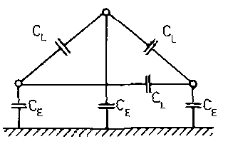
Figure 20. Equivalent connection
diagram of the capacitances of - a three-phase overhead line, CL
conductor-conductor capacitance, CE conductor-earth capacitance
The mutual capacitance of a three-phase overhead line is
calculated as follows:
The admissible values of capacitance and reactance are
Table 3 Influence of circuit elements on the behaviour of lines
with respect to different types of voltage and current
Elements
Low voltage
Medium and high voltage
Direct current
Three-phase current
Line resistance
heating UV, PV
heating UV, PV
heating UV, PV
heating UV , PV
Insulation resistance
insulation and corona losses are low
insulation and corona losses increase with increasing voltage,
therefore from 110 1<V bundle conductors for overhead lines
low corona losses
insulation between several conductors to be considered, e.g. in
multi-conductor cables
Line inductance
self-inductance effects in the event of switching operations,
little inductive phase shift since short line length
self-inductance effects in the event of load variations,
inductive phase shift increases with increasing line length
self-inductance effects only when switching on and off
with 2 three-phase systems and operating currents flowing in
opposite directions the self-inductance effects are compensated
Line capacitance
low
medium to high
capacitance increases with increasing line length and voltage
line capacitance depends on distance between each of the three
conductors, on the insulation and screening
4.6.2. Lines for heavy-current installations
Bare (plain) lines
Bare lines are non-insulated conductors installed on insulating
bodies (insulators), outside the area of contact on poles, behind protective
grids or inside casings. As earth leads, bare lines are layed in the soil and in
the area of contact.
- Bars (rails)
Solid, non-insulated conductors which, because of their shape or
cross section, are highly resistant to deformation. They may be marked by colour
codes.
Table 4 Bar (rail) sections and section moduli
No. Section
Position of conductor bars to each other
Section moduli
1 flat
high compared to 2
2 flat
low compared to 1
3 tubular
very high compared to 4
4 round
low compared to 3 and 1
5 channel
very high compared to 1 to 4
The bars are connected by welded or screwed connections.
They are held by line carriers on porcelain insulators or
without carriers on thermoset plastic insulators or in hard paper fans.
Figure 21. Pin-type (rigid-type)
insulator - 1 support, 2 bar carrier for two busbars (laid on edge)
Table 5 Hard paper boards for fixing of busbards
Designation
Construction
Comments
Hard paper fan
easy mounting
Hard paper fan with end strip
better hold compared to simple fan
Hard paper board with recesses
to be used where high bending stresses may occur (short circuit)
- Busbars
Busbars are bars or ropes to which several conductors or lines
for current supply or derivation are connected. They are selected according to
the current load (thermal load) from tables. Painted busbars can resist higher
loads because the paint enables better dissipation of heat. The admissible D.C.
load is higher than the A.C. load. Due to the skin effect of A.C. the cross
section is not fully utilized. Therefore, pipe sections etc. are used in
high-voltage installations. In order to avoid the accumulated temperature
(ambient temperature V.. plus conductor temperature V,) to be exceeded, the
admissible load current is to be reduced (load reduction) in the event of a
higher ambient temperature. This can also be influenced by the way of laying.
Table 6 Cooling at flat section
Way of laying
Use
Cooling
On edge, horizontal
busbar current bar outlet
good
On edge, vertical
busbar
good
Flat, horizontal
current bar
very bad
Flat, vertical
outlet
good
Load because of temperature changes results in displacement of
the busbars. Such temperature difference, which may be caused by varying heating
effect of the current (alternating load) and by varying ambient temperature of
busbars, results in change of length. Busbars are, therefore, fixed in line
carriers which permit sliding and/or expansion joints are included in the course
of the line. The slide supports and expansion joints make the expansion forces
ineffective.
Figure 23. Expansion joint - 1
expandable portion of a multitude of thin strips, 2 connection piece
Loads by heavy currents, such as in the event of short circuit,
generate a heavy magnetic field around the conductor. Heavy forces may occur
between the fields. Their effect depends on the instantaneous short-circuit
current, supporting point distance, conductor section, type of laying and
conductor distance.
- Current bars
Current bars are rigid conductors for the transmission of
electric energy to portable devices through current collectors. They are used as
series line in low-voltage and high-voltage installations. The main materials
are half-hard rolled copper or aluminium.
Example:
Figure
- Earth leads
Earth leads are bare conductors lying in the soil with a firm an
conductive connection with the soil.
The main materials for protective earthing and system earthing
lines are:
· hot galvanized or
copper clad strip steel or round steel with a minimum cross section of 50
mm, · aluminium sections or rope with a
minimum section of 35 mm, · copper sections
or rope with a minimum cross section of 16 mm, · steel rope with a cross section of 120 mm
²
Table 7 Customary minimum cross sections of earth leads
Type of earth lead
Semi-finished products
Minimum cross sections/dimensions
Customary size
Strip earth conductors
strip steel
100 mm² min. thickness: 3 mm
30 mm x 4 mm 40 mm x 5 mm
round steel
diameter: 10 mm
diameter: 10 mm, 12 mm, 13 mm
Earth rods
mild steel tube angular steel or other similar sectional or
round steel
diameter: 24 mm min. wall thickness: 3 mm 40 mm x 40 mm x 4 mm
diameter: 33.5 mm (1”) diameter: 60 mm (2”) 40 mm x 40
mm x 4 mm
Earth leads are interconnected by screwed, clamped and welded
connections.
- Contact lines.
Contact lines are used for electromobiles with and without
longitudinal carriers including safety stop cables. Conductors of sectional
rails in workshops, on ceilings, under bridges, in tunnels and passages are also
belonging to the contact lines.
Table 8 Contact lines, types and use
Designation
Material
Type of section
Purpose of use
Steel-copper contact line
Contact line with steel core and copper sheathing
No high resistance to wear, suitable for subsidiary routes with
normal traffic and low speeds 1 copper sheathing 2 steel core 3 groove for
fixing purposes
Copper contact wire
Solid copper section
as above but without steel core
Ri 80, Ri 100, Ri 120. use for standard-gauge railways
Steel contact line
All-steel contact line
For replacement purposes only, for short routes with little
traffic
0 Steel current bar (rail)
Sectional steel rail with aluminium reinforcement
High resistance to wear, suitable for city or underground
railway routes as feeder bar beside the track (only when provided with its own
track bed - self-contained facilities) 1 steel rail section 2 aluminium
subsequently or additionally added to enlarge the cross section 3 pick-up sides
Flat-section type
Copper or bronze
For small contact wires, crane tracks, conveyor equipment
Round-section type
Copper or copperbase alloys, bronze etc.
For crane equipment, conveyor equipment
- Overhead lines
These are open-type lines installed overhead in the open air
with span lengths of normally more than 20m.
In order to place overhead lines out of reach of man and to
ensure freedom of motion for vehicles of any kind, poles are required for
overhead lines. Overhead lines of up to 1000 V, for example, are fixed on
pin-type insulators or shackle insulators. Cap-and-pin insulators or long-rod
insulators are used for rated voltages of more than 1000 V.
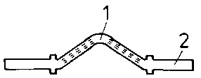
Figure 24. Types of poles - (1)
supporting pole (straight-line pole), e.g. wooden pole with reinforced concrete
pole footing, (2) angle pole, e.g. wooden pole with anchor, (3) angle pole, e.g.
wooden pole with tie, (4) terminal pole, e.g. wooden A-pole (anchor and terminal
pole) 1 wooden pole, 2 reinforced concrete footing, 3 anchor, 4 tie
Figure 25. Pole head types - 1 use
in the voltage range 0.4 to 6 kV as wooden pole or reinforced concrete pole, 2
use in the voltage range 6 to 20 kV as concrete pole (the central conductor is
alternatingly run at the right-hand and left-hand side of the pole), 3 use for
voltages of more than 20 kV up to about 220 kV as lattice steel pole
Open-type lines include, for example, short connection lines in
the area of buildings (over courtyards, between workshop halls etc.).
- Stranded conductors
Stranded conductors are multi-wire conductors which are movable
because of their flexible construction.
- Earthing wires
Earthing wires are used to protect voltage-carrying conductors
against direct lightning stroke or to carry off to the soil over-voltage of
atmospheric or other origin and consequently to avoid or reduce step and contact
voltages on poles and scaffoldings.
Marking of bare lines
Table 9 Identification colour codes for power
transmission lines
Type of current
Conductor
Colour code
D.C.
L+
red
L-
blue
M
light-blue
Three-phase current
L 1
yellow
L 2
green
L 3
violet
N
light-blue
A.C.
L 1
yellow
L 2
violet
Table 10 Identification colour codes for protective
earthing and system earthing lines
Type of earthing
Colour code
Protective earth
black
System earth
white with black cross-stripes
Joined protective earth and system earth
from the point of joining: black with white cross-stripes
Table 11 Identification colour codes for earthing lines
from the conductor to the earth
Type of current
Conductor
Main colour
Identification colour additional colour as
cross-stripes
Direct current
L+
black
red
L-
blue
M
white
Three-phase current
L 1
yellow
L 2
green
L 3
violet
N, PE
white
PEN
Single-phase A.C. to IEC
L 1
black
yellow
L 2
green
for raiIway facilities
L 1
yellow
L 3
violet
Two-phase A.C.
L 1
yellow
L 2
green
Insulated lines
- Construction
Insulated lines consist of a single insulated conductor or of
multiple conductors insulated from each other and are provided with protection
against impairment of the electric function. Normally they are not allowed for
laying in soil and water.
· Conductor Material:
aluminium or copper, Type of conductor: single-wire, multi-wire or poly-wire,
fine-wire or extra-fine wire.
Shape of cross section: round.
· Insulating cover
consisting of rubber, plastic material, glass silk or artificial silk.
· Sheathing consisting of
rubber or plastic material.
- Wire marking
The insulating covers of multi-wire lines are marked with a
colour code for safety reasons and for quicker working.
· Protective conductor
Colour code of protective conductor: green-yellow,
The green-yellow wire may only be used as protective conductor
or auxiliary earthing wire.
· · Multi-wire lines are produced with or without
protective conductor
· · With flat lines, the wire with the relevant colour
code is to be used as protective conductor.
· · Wire marking
Table 12 Wire marking
Number of wires
Lines with protective conductor
Lines without protective conductor
1
gnge
b1
b1
sw or br
sw or br
2
gnge sw (only for fixed laying)
b1 sw or br
3
gnge b1 sw or br
b1 sw br
4
gnge b1 sw br
b1 sw br sw
5
gnge b1 sw br sw
Gnge
green-yellow
br
brown
b1
blue
sw
black
- Abbreviations
All countries are aiming at standardized abbreviations for
marking and identification. The following markings are an example:
· Group markings A wire line
D triple line
F
flat line (ribbon conductor)
Fr
overhead line (wire or rope)
H
hose line
I
installation line (wiring line)
Kr
motorcar supply line
L
tubular lamp line
N
heavy-current line
P
testing and measuring line rubber-sheathed line for mines
R�
X-ray line
S
special line
Sch
welding line
T
trailing line
TS
trailing line, multi-wire
TM
trailing line, single-wire
W
heater line
Z
twin line
Z�
ignition line
· Constructional elements
C
shield of metallic wires or conductive layer
CE
like C, but around each wire
G
insulating cover or sheathing of elastic material (rubber)
2G
insulating cover or sheathing of silicone rubber
GS
insulating cover, protective cover or fibre core of glass silk
- Insulated power lines for fixed laying - examples
· Lighting line
Abbreviation: NLZYF 2 x 0.5 - ws - (Un = 300/300 V). Fine-wire
Cu-conductor, plastic (PVC) insulating covers. Both wires are in parallel.
Preferential colour: white. Application: in and at lamps with fixed laying. For
dry and sometimes damp rooms, in and at lamps.
· Plastic-insulated line
Abbreviation: NAYY-J 2 x 2.5 re - 1 kV - (Un =1 kV).
Single-wire, round Al-conductor, plastic (PVC) insulating covers and sheathing
with green-yellow wire. Universally applicable in all media for wiring and
control purposes.
· Plastic-insulated wire line
Abbreviation: NY b 10 - bl - (Un = 300/300 V).
Poly-wire Cu-conductor, plastic (PVC) insulating cover, wire line for protected
laying (wiring). For installations, in and at machines, in cases of vibrations
and frequent bending stress, in dry and sometimes damp rooms.
Table 14 Places of installation and examples of
applications of insulated power lines for fixed laying
Type of line
Abbreviation
Rated 3) voltage
Application 2) Place of installation
Examples of applications
-
-
kV
1
2
3
4
5
6
7
8
--
Lighting line
NLZYF
0.3/0.3
x
-
-
-
-
-
-
-
in and at lamps
Tubular lamp line
NL2YY
7.5/7.6
x
-
-
-
-
-
-
-
advertisement illumination,
NL2YCY
7.5/7.5
x
x
-
-
x
x
x
x
particularly outdoors
Rubber-sheathed line
NIAGG�u
0.45/0.45
x
x
-
-
-
-
-
x
for illumination purposes
Silicone rubber- sheathed line
N2G
1 1)
x
-
-
-
-
-
-
x
in lamps, in and at thermic
N2Gf
appliances, in hot rooms
Installation lines
NIAZY
0.3/0.3
x
-
-
-
x
-
-
-
flush with intermediate ceiling installation
NIDAY
0.3/0.3
x
-
-
-
x
-
-
-
buried in bulk walls and ceilings and with underfloor and
intermediate ceiling installation
Plastic-insulated cable
NYYD NYY
1
x
x
x
x
x
x
x
x
universally applicable for wiring and control purposes
NAYYd
NAYY
Plastic-sheathed line
NIYYf1
0.3/0.5
x
x
-
-
x
x
x
x
for wiring and control purposes
NIAYYf1
NILAYYf1
Plastic-insulated wire line
NY
0.3/0.3
x
-
-
-
-
-
-
-
for installations, in and at machines, in cases of vibrations or
frequent bending stress
NYb
NAY
N2AY
Special-purpose
NSYb
0.6/1
x
-
-
-
-
-
-
-
for ships, rail vehicles
plastic-insulated
NSYf
wire line
Rubber-insulated
NGUb
0.6/1
x
-
-
-
-
-
-
-
rail vehicles
wire line
1.8/3
3.6/6
NGUf
0.6/1
1.2/2
special-purpose
NSGGf�u
1.8/3
x
x
-
-
-
x
x
-
rail vehicles
rubber-insulated
NSGCGf�u
and
wire line
NSGCGf�uk
3.6/6
Explanations of the figures
1) up to 1.5 square millimetres rated voltage 300/500 V
from 2.5 square millimetres rated voltage 450/750 V
2) 1 dry and sometimes damp rooms 2 damp or wet rooms or
outdoors 3 in soil 4 in water 5 flush or buried 6 on the surface, on
trays and supporting brackets 7 on wood, cardboard, particle board or
fibreboan 8 when there is a possibility of direct contact of the line
3) Rated voltage indicated as conductor-earth
voltage/conductor-conductor voltage
- Insulated power lines for portable equipment - examples
· Triple line
Abbreviation: NDY 3 x 0.75 - gr - (Un = 300/300 V). Fine-wire
Cu-conductor, plastic (PVC) insulating cover. The three wires are in parallel.
Colour: grey. For light portable devices (kitchen appliances, radio and TV
sets), no thermic appliances and no extension line, in dry and sometimes damp
rooms and when there is a possibility of direct contact of the line.
· Light plastic hose line
Abbreviation: NHYY1 3 x 0.75 - gr - (Un = 300/300 V). Fine-wire
Cu-conductor, plastic (PVC) insulating covers and sheathing. Colour of
sheathing: grey. For office machines, vacuum cleaners, refrigerators, in dry and
sometimes damp rooms and when there is a possibility of direct contact of the
line.
· Medium shielded plastic hose
line Abbreviation: NHYYCY 3 x 1 - gr - (Un = 300/500 V). Fine-wire Cu-conductor,
plastic (PVC) insulating covers, inner and outer sheathing. Shield of Cu-wire
mesh. Colour of sheathing: grey. For medium mechanical stress, extension lines,
shielding electric fields, for control purposes, in dry and wet rooms, in the
open air, in water, on wood, cardboard, particle board and fibreboard and when
there is a possibility of direct contact of the line.
Table 15 Places of installation and examples of
applications of insulated power lines for portable equipment
Type of line
Abbreviation
Rated voltage
Application Place of installation
Examples of applications
-
-
kV
1
2
3
4
5
6
7
8
-
Twin line
light portable devices,
Triple line
NZY
0.3/0.3
x
-
-
-
-
-
-
x
no thermic appliances and extension lines
Plastic hose lines: especially light light
NDY
0.3/0.3
x
-
-
-
-
-
-
x
NHYY11
0.3/0.3
x
-
-
-
-
-
-
x
NHYY1
0.3/0.3
x
-
-
-
-
-
-
x
office machines, vacuum
NHYY1f1
cleaners, refrigerators
medium
NHYY
0.3/0.5
x
x
-
x
-
-
x
x
for medium mechanical stress, extension lines
medium shielded
NHYYCY
0.3/0.5
x
x
-
x
-
-
x
x
like NHYY, shielding of electrical fields, for control purposes
for medium mechanical stresses, workshop devices, tools, also
outdoors, agricultural imple ments
Rubber hose lines: heavy
1)
NSH
0.6/1
x
x
-
x
-
x
x
x
for higher mechanical stresses,
NSH�u
construction machinery, heavy
NSH�uk
workshop equipment
NSHCk
1)
heavy with sup porting facili ties
NSHT
0.45/0.75
x
x
-
x
-
x
x
x
for high tensile stress (control purposes in shafts and on hoist
ing gears)
NSHT�u
Rubber hose lines for mines
1)
for underground mines, in pits
NO�
0.6/1
x
x
-
x
-
x
x
x
with firedamp and explosion hazards
with supervisory conductor
NQ��
0.45/0.75
x
x
-
x
-
x
x
x
like NQ� but with supervisory
Welding line
NSCHG�u
0.12/0.2
x
x
-
-
-
x
-
x
interconnection line between transformer and electrode holder
Trailing line
1)
single-wire
NTM
1.8/3
x
x
-
x
-
x
x
x
for high mechanical stress, con
NTM�u
3.6/6
nection of high-voltage motors
NTMC�u
12/20
and power supply installations
NTMC�uk
18/30
1)
(peak-load stations)
four-wire
NTSCE�u
3.6/6
x
x
-
x
-
x
x
x
as above, power supply for big
6/10
equipment (excavators and
NTSCE�uk
12/20
conveyor bridges in open-cast
18/30
lignite mines)
1) except in mining, on building sites and for portable
equipment
- Fabricated power lines - examples
These are industrial, standard lines with integral connectors.
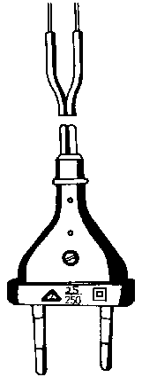
· Mains connection lines
· · Abbreviation: A1-2-32/7 - gr -
Mains connection line (A1) with integral coupler plug, two-pin,
2.5 A (also called
European plug) for appliances of protection class II. Line: NZY
2 x 0.75 mm, length 2 m, dismantling length 32 mm, insulation-stripping length 7
mm. Colour: grey.
Application: mains connection of electrical appliances of up to
I = 2.5 A. Not allowed in the open air and in wet rooms.
Figure 28. Mains connection line with
integral coupler plus 2.5 A
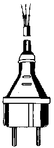
· · Abbreviation: EHI-4-63/7 - sw -
Mains connection line (EHI) with integral safety plug, 10/16 A,
of plastic material and with increased degree of protection for appliances of
protection class I. Line: NMH 3x1 mm2, length 4 m. dismantling length
64 mm, insulation-stripping length 7 mm.
Colour: black. Application: mains connection of electrical
appliances of up to In = 16 A.
Allowed in the open air and in wet rooms.
Figure 29. Mains connection line
with integral safety plug 10/16 A
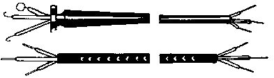
· Interconnection lines
Abbreviation: 22-1, 6-3-32/7 - sw -Interconnection line (Z2)
with integral appliance lead-in of type 3 at one end. Line length: 1.6 m.
Dismantling length 32 mm. Insulation-stripping length 7 mm. Colour: black.
Application: interconnection line with fixed connection at both ends.
Figure 30. Interconnection line with
fixed connection at both ends - 1 with integral appliance lead-in, 2 with outer
braiding
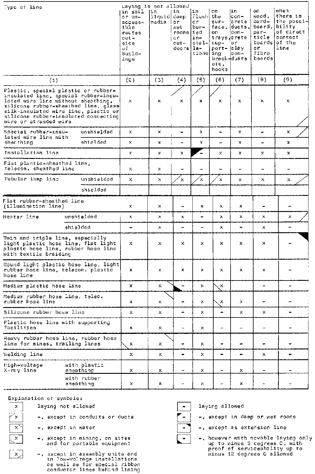
- Not allowed laying of insulated lines
Table 16 Not allowed laying of
lines carrying voltage in
operation
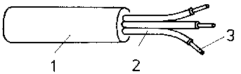
Cables consist of one or more insulated electric conductors.
They are provided with one or more protective layers with properties allowing
the cables to be laid in cable trenches, cement ducts or cable ducts and water
without impairing the electric function.
(The cable construction is always considered from inside to
outside)
Constructional elements
- Conductor Material: aluminium or copper. Type of
conductor: single-wire or multi-wire. Shape of cross section: round, oval,
sector-type.
- Conductor insulation Insulating cover may be made of
· polyvinyl chloride
(PVC), for rated voltage 1 kV, · polyethylene
(PE), for rated voltage up to 30 kV, · paper,
well impregnated with cable impregnating compound up to 30 kV, impregnated with
cable oil up to 380 kV (internationally)
- Core
Conductor with insulating cover.
- Belt
Paper insulation, well impregnated with cable impregnating
compound, in several layers enclosing the core as additional insulation.
- Sheathing
Seamless lead, aluminium or plastic covering, protects the
interior of the cable from external mechanical and chemical effects.
- Inner protective covering
Bitumen-impregnated paper layers with fluid intermediate
bituminous compound which, in the event of mechanical stress (such as bending of
the cable), permit pressure compensation between the metal sheathing or plastic
sheathing and the cable armour.
- Armour
Material: steel.
Type: 2 layers of strip steel with protective coating against
corrosion or round-wire armour, non-magnetized.
Type of wrapping: closed or open (round-wire armouring).
25 % overlapped (strip-steel armouring) and, against special
order, anti-twist wrapping.
- Outer protective covering
Single protective covering of coarse tow yarn or textile tape
with semifluid compound and non-sticking coating - A, double protective covering
as above - AA, protective covering of PVC - Y. Cables with protective covering
of impregnated fibre materials are allowed in rooms if impregnated against
inflammability.
Classification
- Purpose
· control
purposes, · transmission of electric
power.
- Voltage
· low voltage:
³ 42 V ‘= 1 kV (£ 42 V low voltage)
· high voltage: medium voltage 1
to 30 kV. extra-high voltage 110 kV.
- Construction
·
compound-impregnated cable, ·
plastic-insulated cable, · oil-filled cable
for extra-high voltages, · special-purpose
cable, · plastic-insulated cable with more
than five cores.
Wire marking
- Purpose
Marking of the wires largely precludes that the wires get mixed
up and. therefore, is in the interest of higher reliability of service and
easier installation.
Wire marking is not necessary for cable of more than 1 kV.
Up to 1 kV the wire marking corresponds, to a large extent, to
that of lines. The marking of the protective conductor is of special importance.
The green-yellow wires are to be used as protective conductors.
- Type of wire marking
For the benefit of unmistakable definition of the type of wire
marking (especially where two types are possible) of a multi-wire 1 kV cable,
the letter code has been extended to include 3 and 0.
Examples:
NAYY-J 4 x 25 re 1 kV four-wire plastic-insulated NAYY cable
with a wire marked green-yellow or with figure code 3-1-2-3.
NAYY-0 4 x 10 re 1 kV four-wire plastic-insulated NAYY cable
with a nominal conductor cross section of up to 50 mm and the colour code
gnge/b1/sw/br or with figure code 1-2-3-4.
NAYY 1 x 185 sm 1 kV single-wire plastic-insulated NAYY
cable. Table: Wire marking of 1 kV cables
Table 17 Wire marking of 1 kV cables
Wire marking
Type of cable
by colours
by figures, colours or letters
cables with green-yellow wire (letter “J”)
cables without green-yellow wire (letter “O”)
cables with a green-yellow wire or with a wire marked with
the letter J (letter “J)
cables without a green-yellow wire or without a wire marked
with the letter 3 (letter “O”)
(1)
(2)
(3)
(4)
(5)
Compound-impregnated cables
single-wire
nf or sw
-
-
or plastic-insulated cable
two-wire
gnge/nf or gnge/sw
-
J-1
-
more than 35 mm2
three-wire (also cables with concentric conductor or Al
sheathing
-
nf/nf/nf or sw/sw/sw
-
1-2-3
four-wire
gnge/nf/nf/nf or gnge/sw/sw/sw
nf/nf/nf/nf or sw/sw/sw/sw
3-1-2-3
1-2-3-4
NYY, NAYY, NYYd, NAYYd with a conductor cross section up to
2 35 mm²
(l) Sequence of figures 1 to 37 from inside to outside (2)
Seven-wire plastic-insulated cables have one gnge-wire, plastic-insulated cables
with more than 7 wires do not have a gnge-wire. Deviations are
possible.
Note: When using the gnge wire marking, one of these
colours should cover not less than 30 % and not more than 70 % of the wire
surface of each 15 mm long wire portion,
Cable designation
To get clear and full information of the specific technical
construction of a cable and to avoid extensive description, standardized
abbreviations for cables are also aimed at. The following markings shall also
serve as an example:
- Insulating cover
Y PVC insulating cover 2Y PE insulating cover O oil
insulation
- Shield
H shield of wire
- Concentric conductor
For 1 kV cables with an electrically effective cross section of
Fa
flat-wire aluminium
Fu
flat-wire copper
Ra
round-wire aluminium
Ru
round-wire copper
For
1 kV cables with an electrically effective cross section of
Ca
aluminium
Cu
copper
- Sheathing
K
lead sheathing
Ka
aluminium sheathing
Y
PVC sheathing
- Armour
B
strip-steel armouring
Ba
aluminium armouring
BY
rigid-PVC armouring
R
round-wire steel armouring
G
anti-twist steel armouring
- Protective covering
A
single protective covering
AA
double protective covering
Y
PVC protective covering
- Protection against corrosion
· K
single protection
· KK
double protection
(Letter is omitted for cables with sheathing or concentric
conductors of aluminium.)
- Types of conductors
e
single-wire
m
multi-wire
r
round
s
sector-type
- Additional marking of constructional elements
o
open-type armouring, e.g. Ro
w
corrugated constructional element Kaw
z
hardening additive Kz
v
cross-linke
d
2Yv d twist-marked Yyd
- 1 kV cables
J
with green-yellow wire or with wire figure
0
without green-yellow wire or without wire figure 0
- Examples
NYKY
plastic-insulated cable with Cu-conductors, lead sheathing and
plastic protective covering
NAYKY
plastic-insulated cable with Al-conductors, lead sheathing and
plastic protective covering
NAYY
plastic-insulated cable with Al-conductors and plastic sheathing
NAKY
paper-insulated compound-impregnated cable with Al-conductors,
lead sheathing and plastic protective covering
···· A
outer protective covering of coarse tow yarn or textile tape
with semifluid compound and non-sticking coating
··· Y
with outer protective covering of PVC
··· BA
with strip-steel armouring and outer protective covering of
coarse tow yarn or textile tape
··· RoA
with open-type round-wire steel armouring and outer protective
covering of coarse tow yarn or textile tape
··· RG
with anti-twist round-wire steel armouring
NY2YHCaY
polyethylene-insulated cable with wire shields, concentric
conductor of aluminium strips and flat-wire aluminium, PVC sheathing
Note:
In the case of copper conductors the A is omitted after the N in
the abbreviation.
Manufacturing types
- Compound-impregnated cables
Paper-insulated power cables. Single-wire or multi-wire
low-voltage or high-voltage cables with compound-impregnated or
compound-impregnated and drained paper insulation. They may have a metal
sheathing cladding all or individual wires and, in addition, special protective
coverings, depending on the purpose of use.
- Belted cables
The simplest cable from the manufacturing point of view. They
are produced with three or four wires.
· Properties
The poor thermal conductivity of the belt increases the heating
of the cable. The impregnation compound presses outwards, cavities are formed
inside. Increasing danger of glow discharge, enhanced by increased rated
voltage.
· Use
In installations with rated voltages of up to 10 kV.
- Hoechstaedter cables (H-type cables)
Cables with individual shielding of the wires, without belt.
· Properties
The mutual contact of the wire shielding and metal sheathing
(electrically conductive) restricts the electric fields to the wire insulation
· Use
In installations with rated voltages of up to 30 kV.
- Single-conductor cable
Differs from the normal construction of cables. Expensive
manufacture.
· Properties
Good thermal conductivity, thus higher current-carrying
capacity; high short-circuit strength (When laid on cable trays, registers etc.
and on cable lifting points at terminal boxes, special measures of fixing of the
cables may be required in view of the high dynamic effects of possible
short-circuit currents); easy instal-lation and repair. Higher additional losses
because of magnetic fields inside the cables and of mutual magnetic influence of
several cables (three-phase systems)
· Use
In D.C. and three-phase installations of any rated voltage.
- Separate lead type cables (SL-type cables)
Combination of three single-conductor cables - without pressure
protection and armouring - into one cable.
· Properties
The greater mass of metal (metal sheathings) results in better
thermal conductivity, thus good electric shielding of the conductors against
each other, reduction of losses.
· Use
In 20 kV and 30 kV installations.
- Plastic-insulated cables
Plastic-insulated cables are cables with plastic material used
as insulating, filling and sheathing materials.
· Advantages compared to
compound-impregnated cables The costs of manufacturing and processing of
plastic-insulated cables are considerably lower than those of conventional cable
manufacture and processing. Advantages include: considerably smaller mass,
better colour coding, higher elasticity and easier processing.
· Use
In installations with rated voltages of up to 30 kV.
· Types
Cables with plastic-insulated cores and plastic inner sheathing,
armouring and outer covering, such as NAYBY.
Cables with plastic-insulated cores, concentric outer conductor
and plastic outer sheathing, such as NAYFaY.
The various plastic coverings are chemically composed according
to the relevant purpose, i.e. sole purpose of insulation (dielectric strength,
core insulation), sole purpose of filling (filling of cavities, filler material)
as well as purposes of protection against chemical and mechanical influences
(outer sheathing)
· Polyethylene (PE) proved to be
particularly suitable as raw material for core insulations and sheathings.
- Special-purpose cables
This term covers all cables for special purposes of use:
· Power cables for
ships NMYCY. · Aerial cables NLAYYT,
NLA2YvHCaeYT. · Radiation-proof cables
NXGG.-
Such cables are exposed to extraordinary conditions at the place
of installation, such as high thermal and chemical as well as extreme mechanical
stresses.
- Plastic-insulated cables for control and information purposes
They differ from power cables by a higher number of cores (7 to 37 cores) and a
cross section ranging from 1.0 to 6.0 mm Cu and 2 2.5 to 6.0 mm Al. They are
produced as plastic-insulated cables.
· Properties
Special colour code and a specific way of counting the cores.
Compared to multi-conductor cables of the same cross section,
the load on the cores is considerably lower because of the very poor heat
dissipation (massing of cores).
· Use
Such cables are generally produced up to a rated voltage of 1 kV
only and used in heavy-current installations for measuring, signalling and
control
purposes.
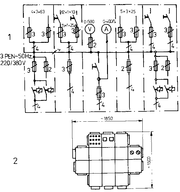
4.7. Switching and distributing plants and accessories for the transmission and distribution of electric energy
4.7.1. Switching and distributing plants
Standard system of modular vessels
It is a modern system of modules that can be universally
combined and be used in electrical and electronic engineering. Such a system
enables a high packaging density in electrical installations/plants.
The vessels serve for covering and/or housing of components,
modules, subassemblies, units and devices. The vessels can be classified in
groups of order.
- Zeroth order vessels
Circuit cards, card plug-in units (non-protected), card inserts
(non-protected)
Use:
The assembled printed circuit boards of standard sizes including
plug-and-socket-connectors or terminal connectors are intended for use in
vessels of 1st or 2nd order.
- First order vessels
Plug-in units and card inserts (protected), card plug-in units
and card inserts (shielded), rack plug-in modules, rack inserts. Use:
As complete modules, mostly as self-contained functional units.
As rigidly built-in or plug-in units they are used, for example,
to complete the tiers in a cabinet. Together with the zeroth order vessels they
fulfil the mechanical functions.
They are the outer enclosure of the final product and have a
decisive influence on the degree of protection, climatic class etc. Besides the
front panels, they determine the shape of the final product. In connection with
the 2nd order vessels they ensure the mechanical functions.
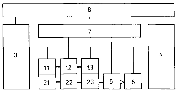
- Fourth order vessels
Subcarriers, plug-in unit carriers, insert carriers, mounting
racks, swing-out racks.
Figure 32. System structure of indoor
switching plants using the standard system of modular vessels (1.1 switchboard
section. 2.2 contactor section, 1.3 capacitor section, e.g. of 400 mm mounting
depth), (2.1 switchboard section, 2.2 contactor section, 2.3 capacitor section,
e.g. of 800 mm mounting depth), 3 subsidiary distribution, 4 energy
distribution, 5 transformer box, 6 peak-load centre, 7 busbar module, 8
structural head of an indoor switching plant
Indoor switching plants
- Use
Switchboard sections, contactor sections and capacitor sections
are intended for universal use as main and subsidiary distributions. All
sections of the same mounting depth can be combined with each other. The
sections of 800 mm mounting depth can be combined with transformer boxes into
peak-load centres (see also Fig. 32).
- Construction
Each section has a busbar chamber, an equipment chamber and a
cable termination and current bar chamber to connect the equipment modules.
- Equipment modules
Plug-in sub-units, plug-in units or inserts to be mounted in the
sections. Plug-in units are connected through plug contacts, inserts are rigidly
built in and connected.
- Sections
The different sections are:
· Switchboard
sections with on-load switches, power circuit breakers, fuses, contactors,
no-load switches, relay modules for information processing.
· Contactor sections with
contactor outlets for various circuits and rated currents.
· Capacitor sections with
capacitors for power-factor compensation.
· Electric power distributors
with power switches, NH-fuse outlets, break-jack points, busbars and/or
combinations for use in power supply substations.
· Subsidiary distributions with
current-limiting power switches, on-load switches and fuses.
· Transformer boxes with
dry-type transformers up to 1000 kVA.
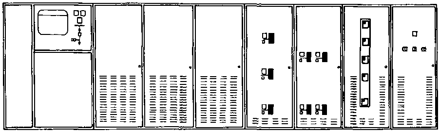
Figure 33. Front view of an indoor
switching plant as peak-load centre (example)
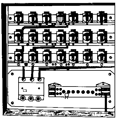
The SLD system offers a variety of possible combinations with a
minimum number of component parts.
- Construction
Sheet steel enclosure of standard size to house switchgear,
transducers, meters, measuring instruments, transformers, pushbutton switches,
signal devices and busbars. The assembled complete distributions are mounted on
supporting racks.
- Use
Wherever electrical devices are to be protected against
moisture, dust and mechanical damage. They are particularly suitable for
industrial, mining and metallurgical operations and building sites.
Figure 34. SLD mounted on supporting
rack with connection lines
Figure 35. Example of a specifically
assembled SLD - 1 general connection diagram, 2 assembly of casings
Standard Box System (SBS)
A metal (aluminium alloy) or plastic box with the relevant
components already mounted by the manufacturer.
- Construction
Table 18 Metal type SBS for IP54 and partly for IP56
Empty boxes
Appliance boxes
Accessories
Screw caps (5 sizes)
Juntion boxes
Cable terminal boxes
Fuse boxes
Flanged caps
Barrier boxes
Insert bowls
Screw caps (4 sizes)
Switches
Sealing sheets
Terminal boxes
Potential equalization rails
Repair switch boxes
Quick-seal couplings
Ballasts
Protective conductor rails
Special accessories
Table 19 Plastic type SBS for IP 54
Empty boxes
Appliance boxes
Accessories
Screw caps (3 sizes)
Junction boxes
Cable terminal boxes
Fuse boxes
Insert bowls
Barrier boxes
Sealing sheets
Terminal boxes
Protective conductor rails
Base-mounted sockets
FDSP, 16 A
- Use
· Plastic boxes are
only used in installations/plants with temperatures up to 60°C. They are
very corrosion-resistant.
· Metal boxes are universally
applicable under extreme conditions. The IP 56 version is mainly intended for
use in shipbuilding.
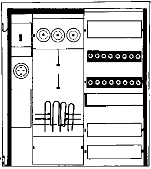
Low-voltage cabinet distributing system (LCD system)
- Construction
Sheet steel enclosure with mounting frame
The mounting frame serves for fixing of the devices and for
holding of the device covers. After mounting and wiring it is bolted in the
cabinet.
Cabinet distributors can be provided with D-fuse sockets up to
B33, NH-fuse sockets up to size 1, gang switches up to 25 A, cam switches up to
100 A, air-break contactors up to IDS, motor protection switches, adapting
transformers, automatic cut-outs and meter boards.
- Use
LCD systems are used in housing and social building
construction, in industry and agriculture.
Figure 36. Example of a central house
connection box
Figure 37. Example of a distributing
cabinet for a house wiring system
Outdoor switching and distributing cabinets
Cabinets for switching purposes and distribution of electric
energy, e.g. for use in the building industry, in traffic engineering, rail-way
facilities, street lighting, agriculture, on building sites.
Figure 38. Example of a cable
terminal box 1 equipment support
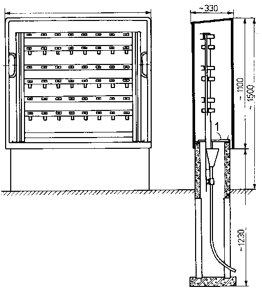
Medium-voltage switching stations, substations and transformer
stations
- Switchgear cubicles (cells)
Of metal-enclosed or open (solid insulation) type, they are used
as line and on-load switch cubicles, cable and measuring cubicles in switching
stations for industrial power supply (metal-enclosed types) or in closed
electrotechnical rooms, particularly for switching of transformers, and on heavy
open-cast mining equipment (solid insulation).
Table 20 Technical data of switchgear cubicles
Switchgear cubicle
Insulation voltage
Rated current
Metal-enclosed type
12 kV
1250 A
or 2500 A
Solid insulation type
36 kV
1250 A
- Substations
Buildings mostly constructed from industrially prefabricated
assemblies, brickwork or concrete. They serve to transmit the electric energy
through cables to the medium-voltage and low-voltage levels. They have separate
medium-voltage and low-voltage chambers.
Figure 39. Example of the layout of a
substation with cable connections - 1 cable entries/exits, 2 transformer
chamber, 3 low-voltage switching plant chamber, 4 medium-voltage switching plant
chamber
· Equipment
· · Medium-voltage switching plant 6 and 10 kV with
semi-open or sheet steel-enclosed switchgear cubicles 15 and 20 kW with sheet
steel-enclosed switchgear cubicles 30 kV with solid-insulation switchboard
sections
· · Low-voltage switching plant with indoor switching
equipment having the following purposes or functions: connection of oil-filled
transformers up to 1600 kVa, station service distribution, emergency power plant
(accumulators), measuring processes, connection to earth, lighting
installations.
- Transformer stations
Cable stations, overhead-line stations, pole stations and
outdoor stations.
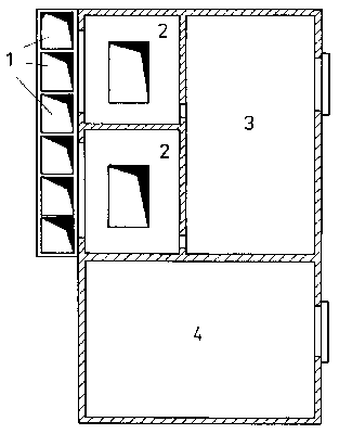
· Cable stations
Buildings of brickwork, concrete or industrially prefabricated
assemblies. They are used as local network stations and for small or medium
industrial plants.
Figure 40. Example of a local
network transformer station (layout) 1 transformer, 2 indoor switching plant, 3
switchgear cells. 4 relays, 5 accessories
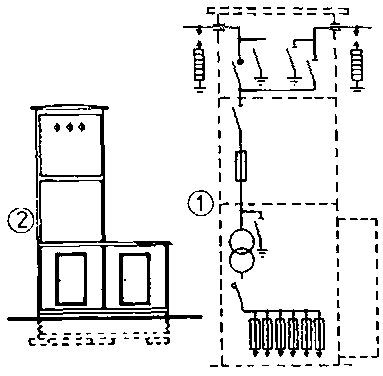
· Overhead-line stations
Buildings like cable stations. They are used as terminal station or
through-station for local networks and smaller industrial plants.
Figure 41. Example of an
overhead-line through-station - (1) schematic circuit, (2) external view
· Pole stations
Transformers up to 160 kVA are erected on a platform at the
overhead-line pole. They are used for overhead line systems in thinly populated
areas with low power consumption.
· Outdoor stations
Transformer stations for temporary supply of electric energy for
building sites, mining projects, mass events etc.
They are enclosed and can be moved on skids or wheels.
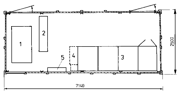
Figure 42. Schematic drawing of an
enclosed outdoor station on skids - 1 medium-voltage switching plant, 2
transformer, 3 low-voltage switching
plant
4.7.2. Switches
General
Switches are devices to open (break) and close (snake) current
paths with all parts necessary for connecting or disconnecting firmly mounted on
a joint base.
The force necessary for changing the switch position (ON/OFF) is
provided by switch drives, such as
- hand drive - magnet drive - motor drive -
compressed-air drive
Low-voltage switches
The following types are in use:
- No-load switches
They must only be switched without load.
- On-load switches
They are designed for switching under load. Different types are:
· Installation (or house-wiring)
switches
On-load switches designed for low-voltage electrical
installations in rooms of residental buildings, industrial buildings and annexed
buildings.
They are designed for a rated voltage of 250 V and for rated
currents of 6 A and 10 A. They are classified according to
· · the mode of switching (e.g. cut-out switch, two-way
switch, intermediate switch), the mode of driving (e.g. toggle switch, rocker
switch, rotary switch, push-button switch),
· · the type of installation (surface switch, flush
switch, appliance switch),
· · the place of installation (e.g. moisture-proof
switch, explosion-proof switch).
· Remote-controlled installation
switches
Electromagnetic switches controlled by a low voltage of 12 V or
by 220 V
· They are used in residental
and social buildings.
- Overload circuit breakers
They are mainly used as motor switches to master high starting
currents. They are tested by 10 to 20 times the rated current. Different types
are:
For distribution of separate lead type cables with each cable
core with sheathing ending in a single-conductor terminal box.
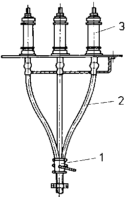
Figure 44. Distribution clip (end
clip) 1 end clip, 2 metal sheathing, 3 single-conductor terminal box
- Cable sleeves.
- Compensation tanks:
For compensation of the quantity of the impregnation compound in
compound-impregnated cable installations or for compensation of the oil pressure
in oil-filled cables or oil-filled cable installations.
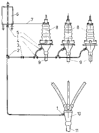
Figure 45. Example of a compound
compensation tank arrangement 1 connecting piece, 2 formed bend, 3 joining
piece, 4 joining T-piece, 5 connecting branch, 6 compound compensation tank. 7
minimum level of compensation tank, 8 single-conductor terminal boxes, 9
single-conductor or separate lead type cables, 10 multiple-joint box. 11 three
conductor
cable
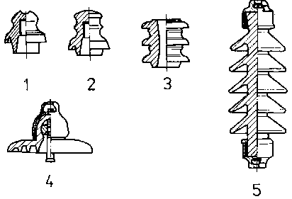
4.7.4. Insulating material (insulators)
Purpose
Insulators shall insulate current-carrying electric conductors
with respect to other conductive parts which are not intended for current
conduction.
Materials
- Porcelain is the material mostly used. It is age-resistant,
corrosion-resistant, has a high mechanical strength and is a good insulator.
Porcelain is used for indoor and outdoor low-voltage and high-voltage
installations.
- Thermoset plastic material is non-corrosive, has a high
mechanical strength and is a good insulator but it is aging and
temperature-sensitive.
- Hard paper (laminated paper) has a high mechanical strength,
is a good insulator but sensitive to moisture and aging. Thermoset plastic
material and hard paper are only used for indoor low-voltage installations.
Stress
- Electric stress
The insulators must be designed so as to preclude breakdown or
spark-over from the electric conductor to parts of the installation which are
not belonging to the electric circuit. Moisture and dirt deposit are favourable
for voltage spark-over.
- Mechanical stress
The insulators in overhead-line installations are subjected to
tensile stress to all sides. The tensile stress is constantly varying, depending
on the weather conditions (e.g. wind, hoar-frost, temperature variations) and
the effects of electromagnetic forces between the conductors. In indoor
installations there is mechanical stress only by electromagnetic effects between
the conductors, i.e. by cantilever force and short-circuit force.
- Thermal stress
Temperature variations in the environment and in the lines have
effects on the fastening elements between the conductor and insulator. Different
heat conductivity and expansion coefficients result in mechanical stress which,
in extreme cases, can destroy the
insulator.
4.8. Laying of lines and cables
4.8.1. General
Damage to the conductor or insulator of any line or cable may
occur as a result of improper transportation, wrong storage and inexpert laying
as well as of fixing contrary to regulations. Insulated lines and cables are
especially susceptible to damage.
Information required for the selection of lines or cables
Table 21 Information required for the selection of lines
or cables
Type of information required
Explanation
1. Amount of load current
Operating current
2. Amount of rated voltage
Low, medium or high voltage
3. Type of laying medium
Air, water, soil
4. Type of laying
Single laying, parallel laying, bunch laying
5. Place of laying
Indoors, outdoors and in soil, in waters, in swampy ground, in
corrosion-developing environment, on bridges and with altitude differences
6. Ambient temperature
Average operating values
7. Mechanical stress, if any
Impact, shock, compression, tensile or bending stress
In any laying of lines or cables it is to be guaranteed that the
lines and cables are fail-safe. This includes
- protection against mechanical damage, e.g. by
covering caps, conduits, - protection against earth displacement, constant
vibrations, - protection against chemical damage, - protection against
excessive heat.
Mechanical stress
The lines and cables must resist bending, tensile and
compressive stress.
To resist frequent, varying bending stress, the conductor can be
divided into several partial conductors of small cross section. Bandages and
armouring are measures to resist compressive stress.
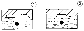
Thermal stress
- Temperature
The temperature of a conductor depends on the current density
(measured in A/mm). the material and the possibility of heat dissipation.
- Lines in bunches
Because of poor heat dissipation, lines laid in bunches must not
be operated with the maximum admissible rated load.
- Admissible heating
Excessive temperatures cause damage to the insulation (increased
brittleness, shrinkage effects and charring, considerably reduced dielectric
strength) which may result in breakdown with total failure of the line or cable.
Laying temperatures
The laying temperature must not be less than the specified
minimum temperature of +4 C because the cable insulation and sheathing material
will get brittle at low temperatures. When the temperature of the cables to be
laid is less than + 4°C, the cables must be warmed up in a 20°C to
25°C warm room, such as a preheating tent, for about 36 to 48 hours,
depending on the cable length. The cables may also be preheated by resistance
heating of the cores by means of a transformer suitable for this purpose. But
the limiting temperature of the conductor must not be exceeded with any heating
method.
4.8.2. Laying of lines
General
For fixed laying of lines (solid system of laying), types of
lines intended for that purpose are to be used only.
The relevant type of line is to be selected depending on the
place of laying.
Places of laying:
- dry and sometimes damp rooms, - damp or wet
rooms or outdoors, - in soil, - in water, - flush or buried, - on
the surface, on trays and supporting brackets, - on wood, cardboard, particle
board, fibre board, - with the possibility of direct contact of the
line.
Laying problems
Lines, whether flush, buried or on the surface, are to be
protected against mechanical damage not only during laying but especially under
service conditions. Invisible lines should be laid vertically or horizontally to
facilitate tracking of their course.
Mechanical protection
Uncovered lines, e.g. moisture-proof lines, must be protected by
conduits at any points where mechanical damage may occur (breakthroughs in
walls, ceilings/floors).
Heat accumulation
With the methods of laying in common use today, such as on
trays, supporting brackets, in ducts and conduits, the lines are laid in
bunches. In each line bunch (single or multi-wire) and in each closed duct, heat
may accumulate. In order to prevent accumulation of heat, the current load
factor for the respective type of laying is to be taken into consideration in
the selection of the line cross
sections.
4.8.3. Laying of cables
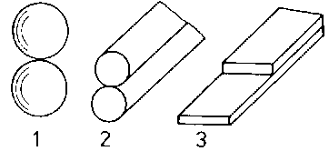
Bending radii
In cable laying, when drawing off the cable from the cable drum
and laying out the cable, e.g. with cable loops and cable connections the
admissible bending radii are to be observed.
Table 22 Bending radii for power cables
Type of sheathing
Laying Position
Minimum bending radius
Lead and aluminium sheathing
during laying or bending final position
20 d 15 d
Plain aluminium sheathing
during laying or bending final position
25 d 20 d
Plastic sheathing
during laying or bending final position
15 d 10 d
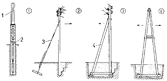
Laying in soil
Laying of cables in the soil depends on the various different
local conditions.
Table 23 Minimum laying depth with and without cable
cover
Rated voltage
Type of cable
Dimensions Built-up ground with cover
Ground not built-up with cover
without cover
-
m
m
m
up to 1000 V
with concentric conductor or metal sheathing
0.45(1)
0.7(1)
without concentric conductor or without metal sheathing
0.45
0.7
1.0
more than 1 kV
Compound-impregnated and plastic-insulated cables Oil-filled
cables
0.7 1.0
(1) Instead of the cover, warning tape is to be preferably used.
The minimum laying depth refers to the bottom edge of the top
cable in one cable route. Laying depths of less than0.7 m in public
traffic areas are subject to the approval of the respective local authority.
Cables in cable trenches are to be arranged on a 10 cm thick
coat of sand. Moreover, the cable is to be covered by another 10 cm thick coat
of sand after laying. The top coat of sand is then to be covered by the cable
protecting cover. The following cable protecting covers are in use:
- Cable protecting caps
It is to be ensured that the cable protecting caps covering the
cable are filled with sand. Any cavity between the cable and the cable ducts
will result in accumulation of heat which largely reduces the load-carrying
capacity.
Figure 46. Cable protecting cover
with cable protecting caps - (1) correct application, (2) cavity between
protecting cap and cable
- Brick covers
Brick covers are low-cost protecting covers and enable quick and
easy covering.
- Concrete covers
Instead of bricks, concrete slabs may be used. They should be
generally used for laying of oil-filled cables.
Figure 47. Cable protecting cover
with concrete slabs and bricks - (1) with concrete slabs, (2) with bricks
- Cable conduits, moulded ducts
Cables run into buildings or under streets, rails and
traffic-able ways require a high degree of mechanical protection. Conduits of
clay, concrete or steel (not for single-conductor cables) are used for this
purpose. If several cables are to be laid next to one another, moulded ducts are
used.
Figure 48. Moulded duct
For the transition from the covering protection to the conduit
it is to be made sure that the cable is not subjected to compressive or shearing
stress.
- Cable layout in the soil
If several cables are laid in one cable trench, the lateral
distance between the cables should be about 7 cm. Deviations are possible.
If high-voltage and low-voltage cables are laid in one cable
trench, the high-voltage cables are to be laid deeper than the low-voltage
cables.
Cable laying in the air
Cables should be circulated by air from all sides. Complete air
circulation will not always be possible, e.g. in closed cable registers and
laying of cables in ducts. In such cases a reduced load is to be calculated.
- Cable runs one upon the other High-voltage cables on the lower
registers, low-voltage cables on the upper registers. Cables in ducts must not
be laid on the bottom since the armouring would corrode in the event of
intrusion of water. Cables intended for the protection, monitoring, control of
plants or for transmission of information are to be laid separately from cables
with rated voltages of more than 1 kV. Multi-conductor cables or cable systems
with rated voltages of more than 1 kV should not be laid in layers one upon the
other.
- Fixing of cables
Cables are to be fixed so as to prevent any deformation which is
detrimental to the service properties. For cables on ceilings and walls it is
also important to ensure good appearance.
Table 24 Distances for support and fixing of
multi-conductor cables
Distances: in metres
Metal-sheathed cables
Plastic-insulated cables
Support horizontal
Fixing vertical
Support horizontal
Fixing vertical
<1
<3
<1
<1
=
=
=
=
- Distances
A minimum distance of 2 cm between the cables and between the
cable and the wall is to be maintained to prevent accumulation of heat in
service.
Laying in water
Laying of cables through inland waters (e.g. rivers, lakes and
channels)
Cables in the open sea are laid by specialized companies by
means of laying ships.
- Types of laying
· Laying on the
bottom of stagnant waters. · Laying in a
dredged channel. · Laying in conduits - only
in brooks, ditches and rivulets. · Setting of
cables or cable conduits into the water bottom.
- Type of cable
The cable must have a strong armouring and good protection
against corrosion. Plastic covering or double protective covering of impregnated
fibrous material (AA) is suitable for this
purpose.
4.8.4. Electric connections
General
Conductors must be connected to machines and appliances, i.e.
they must have an electrically conductive connection. A connection between
conductors is also necessary. The connection must enable reliable flow of
current from one conductor to the other one. That means, there must be good
contact between the conductors at the joint.
Figure 49. Types of contact - 1 point
contact, 2 line contact, 3 surface contact
1. What are medium-voltage systems? 2. What is the difference
between open and closed systems? 3. What is the purpose of network system
coding to IEC 445? 4. What is the importance of the voltage in plant
engineering? 5. What are the effects of the intensity of current to be
transmitted on plant engineering? 6. What does the term “distributing
plant” mean? 7. How can the change of length of busbars caused by
heating be coped with? 8. What is the basic construction of a line? 9.
What is the basic construction of a cable? 10. What is the advantage of a
standard system of modular vessels for electrical engineering? 11. What types
of switching and distributing plants do you know? 12. What is the purpose of
switches? 13. What materials are insulators made of? 14. What is generally
to be taken into account in laying of lines and cables? 15. What is to be
ensured in cable laying with cable protecting caps? 16. What is the purpose
of electric
connections?