Making Fastening Joints - Course: Basic skills and knowledge of electrical engineering. Trainees' handbook of lessons (Institut f�r Berufliche Entwicklung, 15 p.)
3. Making Detachable Electrical Joints (Connectors)
Conductive electrical joints are made by connecting (clamping)
the wires to a connection element (screw connector). Depending on the material
and cross section of the wire, such connection is of direct or indirect type.
With direct connection the wire is held by the screw connector
without any additional means. For large cross sections indirect connection is
used, i.e. cable eyes are fixed to the wire ends by soldering, pressing or
clamping.
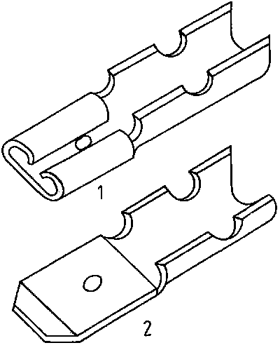
Another way of making conductive electrical joints are plug-type
joints (plug-and-socket connectors).
They are mainly used to connect non-stationary electrical
appliances or to connect plug-in units in devices, appliances and installations.
Plug connectors permit the interchange of assemblies and devices in case of
repair.
3.1. Direct Connection
Direct connection is done in two ways:
Connection of the conductor by means of a wire lug to be bent or
straight-line connection. Flexible conductors must be tin-coated before they are
connected.
Connection of wire lugs
The following rules for connection are to be observed:
- A maximum of two aluminium conductors differing in
up to two cross-sectional steps can be connected.
- A maximum of three copper conductors differing in up to two
cross-sectional steps can be connected.
- Several conductors can be connected to connection bolts if a
pressure piece is inserted after every two aluminium conductors or after every
three copper conductors.
- A washer is to be inserted between the individual conductors.
- For connection of protective conductors or neutral conductors
one conductor per connection point is admissible only.
- Each connection point is to be secured by a lock
washer.
Why must no more than two aluminium conductors be connected to a
connection
bolt? ______________________________________________________________________________ ______________________________________________________________________________ ______________________________________________________________________________ ______________________________________________________________________________
Sequence of operations for making wire lugs
Wire lugs are bent on copper or aluminium conductors of up to 16
mm2 cross section. For flexible copper conductors the maximum cross
section is 4 mm2.
Stripping of the conductor
The stripping length of the conductor depends on the diameter of
the screw joint used.
It can be calculated to:
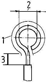
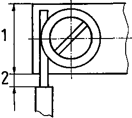
Figure 8 - Representation of a
wire lug - 1 length to be stripped, 2 lug diameter, 3 distance from beginning
of lug to conductor insolation
1 = (d + 0.5) + a 1 = length to be stripped in mm p = 3.14 d = bolt diameter in mm a = distance
from beginning of lug to conductor insulation (d + 0.5) = lug diameter
What tools are used for stripping of
conductors? ______________________________________________________________________________ ______________________________________________________________________________ ______________________________________________________________________________
Bending of the wire lug
The wire lug is bent by means of a round nose plier in the
direction of rotation of the fastening screw.
Figure 9 - Bending of a wire
lug - 1 applying the round nose plier, 2 closing the wire lug, 3 bending of
the lug to the centre of the conductor
The wire end is slightly pre-bent with the round nose plier. The
conical plier noses are to be applied so as to give the correct lug diameter
required. The round nose plier is then to be re-applied for finish-bending of
the lug, preferably in one pass.
The lug should be tested on the screw joint to be used. If the
lug does not have the required diameter, the plier noses are to be applied at a
point where their diameter is slightly bigger to re-bend the lug. If the
required diameter is reached, the lug is bent to the centre of the conductor.
Why must the wire lug be bigger than the connection
bolt? ______________________________________________________________________________ ______________________________________________________________________________ ______________________________________________________________________________
Sequence of operations for connecting wire lugs by means of
screw connectors
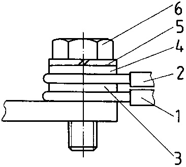
Figure 10 - Construction of a
screw connector - 1,2 conductor, 3,4 washer, 5 lock washer, 6 screw
Unscrewing of the fastening screw
What tool is used for unscrewing a slotted screw and a
hexagon-head
screw? ______________________________________________________________________________ ______________________________________________________________________________ ______________________________________________________________________________
Composing the screw assembly
The screw assembly is to be composed in the following order:
The lugs of the conductors are to be inserted so that the
bending direction of the wire lug complies with the direction of rotation of the
screw.
Tightening of the fastening screw
The complete fastening screw is screwed into the thread by hand
and then tightened with the respective tool.
What is the sequence of operations for making a bolt joint with
4 aluminium
conductors? _____________________________________________________________________________ _________________________________________________________________________ _____________________________________________________________________________
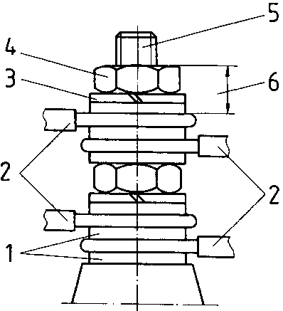
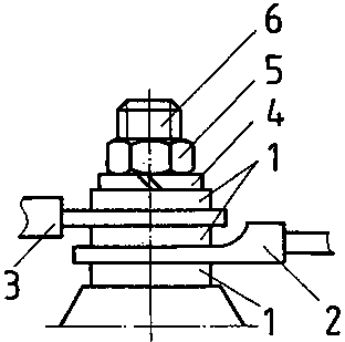
Figure 11 - Construction of a
bolt joint with four aluminium conductors - 1 washer, 2 conductor, 3
lock washer, 4 nut, 5 bolt, 6 pressure piece
Straight-line connection
If lateral escaping of the conductor is limited by the screw
head, bending of lugs is not necessary. The conductor is prevented from escaping
by clamping saddles, distributor plates and connector blocks.
For straight-line connection attention is to be paid to the
following:
- If conductors are fixed at the point of connection by means of
clamping saddles, one conductor per saddle side must be connected only. The
conductors may differ by one cross-sectional step.
- If conductors are fixed by means of cap screw and
distributor plate, one conductor per distributor plate must be connected only.
The conductors must have the same cross section. The conductor(s) is (are) to be
inserted so that it (they) will be drawn into the point of clamping when the
screw is tightened.
Figure 13 - Connection of
conductors by means of cap screw and distributor plate - 1 distributor plate,
2 washer
- If conductors are fixed by means of connector blocks,
no more than two conductors, which have been soldered first, must be connected
at each side.
Figure 14 - Connection by
means of connector block
Sequence of operations for straight-line connection
The sequence of operation for connection by clamping saddles,
distributor plates and connector blocks is the same:
Stripping of the conductor
The stripping length depends on the size of the clamped joint.
To avoid clamping of any conductor insulation, the stripping
length must be approx. 1... 2 mm longer than the clamped joint.
Figure15 -
Determination of the stripping length - 1 size of the clamped joint, 2
1... 2 mm in excess
Unscrewing of the fastening screws
The fastening screws are unscrewed just as much as necessary to
feed in the conductor.
Feeding in of the conductor into the clamped joint
The conductor is fed in under available washer or clamping
saddles.
Why must the wire be applied at the left-hand side of a
distributor
plate? ______________________________________________________________________________ ______________________________________________________________________________ ______________________________________________________________________________ ______________________________________________________________________________
Tightening of the fastening screw
The fastening screw is firmly tightened by a screwdriver
suitable for the size of the
screw.
3.2. Indirect Connection
Large conductor cross-sections render the bending of lugs
difficult and would require big screw joints for direct connection. Therefore,
the conductor ends are provided with cable eyes by soldering, pressing and
squeezing.
Connection of cable eyes
For connection of cable eyes the same rules apply as for
connection of lugs.
Sequence of operations for connecting cable eyes to a bolt
joint
- Slackening of the fastening nut -
Composing of the bolt assembly
Bild 16 - Construction of a
bolt joint - 1 washer, 2 cable eye, 3 lock washer, 4 nut, 5 bolt
The bolt assembly is to be composed in the following order:
The fastening nut is screwed on by hand and then firmly
tightened by a wrench.
What is the sequence of operations for connecting a protective
conductor with cable eye to a screw
connector? ______________________________________________________________________________ ______________________________________________________________________________ ______________________________________________________________________________ ______________________________________________________________________________
Combined connection of cable eyes and lugs
It is possible to fasten cable eyes and lugs together to a screw
connector. For connection the same rules and the same sequence of operations
apply to the two types. When composing the bolt assembly, the lug is always to
be put on the cable eye.
Figure17 -
Construction of a bolt joint - 1 washers, 2 cable eye, 3 wire lug, 4 lock
washer, 5 nut, 6
bolt
Plug-and-socket connectors consist of two components, the plug
and the socket. The connections to plug-and-socket connectors (wire connection
or printed circuit conductors) are made by soldering, wrapping, squeezing or
clamping. Plug-and-socket connectors are used in various forms as panel
connectors (flat plug connector) and circular connector as well as single-pole
(tip plug) and multi-pole (multi-point) connectors.