Special Public Works Programmes - SPWP - Planting Trees - An Illustrated Technical Guide and Training Manual (ILO - UNDP, 1993, 190 p.)
Appendices - Technical sheets
Appendix 1 - Surveying and mapping of large planting sites
Appendix 2 - Laying out and preparing soil and water conservation structures
Appendix 3 - Survival count
Special Public Works Programmes - SPWP - Planting Trees - An Illustrated Technical Guide and Training Manual (ILO - UNDP, 1993, 190 p.)
Appendices - Technical sheets
Appendix 1 - Surveying and mapping of large planting sites
Figure
Basic forest surveying and mapping is needed for efficient
planning and management in reforestation. Information on the area is gathered
and a sketch drawn in the field. The final map is completed in the office.
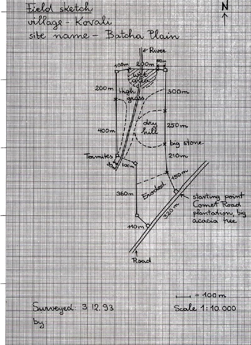
1. Recording of field data and drawing of field sketch
To collect and record the field data, a box compass is needed
and sheets for field notes should be prepared. Try to get hold of maps and
aerial photographs of the area, on as large a scale as possible. This will make
the work easier.
The field work can be divided into three main areas:
(a) General orientation. (b) Gathering of field
data. (c) Drawing the field sketch.
(a) General orientation
First, acquire a general knowledge of the area. Consult maps,
note key points such as forest zone corners, rivers, roads or trails.
Familiarize yourself with the terrain by walking around it and get an overview
of the variation in site conditions.
Surveying and mapping
General orientation
1. Consult map
2 Walk around
Gathering field data
Compass
Aiming
Drawing the map
Protractor
Drawing
(b) Gathering field data
When you have a general overview of the area, start gathering
the field data. Choose a starting point (point 1) that is easy to relocate and
describe. Note it on the sheet.
Example: Point 1 - Corner road and plantation, big Acacia tree,
60 cm in diameter.
Now you have to use the compass. A second point (point 2) along
the side you want to measure has to be chosen. Always choose a clear landmark to
point the compass at - for example, a characteristically shaped tree or a rock.
Occupy point 1, facing the direction of point 2. Hold the
compass steady in both hands with your elbows against your body. Then sight
point 2 by pointing the front sight of the compass to the landmark chosen as
point 2. When the needle stops swinging, read the bearing to the nearest degree.
Record the compass reading in the column provided in the field note sheet in
line with point 1-2.
When using the compass, make sure that it is free from the
effects of magnetism due to iron objects carried by yourself or in nearby
surroundings. Otherwise you will get false readings.
Measuring the distances between the points can be done by
pacing. The number of paces for 100 metres has to be known so that you later can
convert the number of paces recorded into metres. The pace length is individual
and must be measured for each person. For exact maps, a tape chain or a rope
with metre graduations can be used for measuring. Note on the sheet the number
of steps taken to cover the distance. Describe easily defined points and corners
in the field note under the column "note". For example: Stone 1 x 2 m, 1 m high,
east bank of river.
Survey field notes - suggested outline
Location: _________
District: ______________
Plantation: ________
Date inspected: ________
Area: ____________
Inspected by: __________
POINT
COMPAS READING (degrees)
DISTANCE
NOTES
Paces
Metre
1
-
corner road/plantation acacia tree 60 m
1 -2
334
150
heavily eroded area
2-3
356
210
big stone 4x8 metre
3-4
360
250
dry hilly area
4-5
360
300
after 140 m, high grass
5-6
265
250
6-7
256
100
40-100 metres wet
7-8
181
200
high grass, 10 m crossing path
8-9
182
400
termites, high grass after 310 m
10- 11
100
100
30 m river (no problems crossing)
11 - 12
177
360
eroded area after 130 m
12- 13
136
110
13- 1
214
320
along the road
(c) Drawing the field sketch
At the same time as you collect the compass bearings, trace a
field sketch. Orient the sketch so that the top of the map indicates the North.
In the field sketch, mark the starting point as point 1. Mark
point 2 and draw the line between point 1 and point 2. This is just a field
sketch and there is no need to be exact but try to use a convenient scale (do
not make the sketch too small) and to make the line more or less follow the
direction in which you are going (the compass bearing). Then indicate the
details of the area traversed.
As you proceed to the next station, take note of and indicate
carefully the vegetation cover and natural land marks you come across. If you
come across roads, trails streams, take a compass bearing of their direction.
Mark them in the sketch with arrows.
Show the approximate extent of different vegetation covers by
drawing light lines. Use a square on the sketch to indicate corner points.
Large areas may be divided into numbered compartments of 10-20
ha, and sub-compartments of 1-3 ha, to facilitate orientation, planning and
management.
It is preferable to subdivide areas according to natural
features (rivers, ridges), existing roads or tacks, and distinctively different
ground cover (rocky areas, swamps, rich vegetation, poor vegetation).
Figure
2. Tracing the final sketch
Now the rough field sketch should be turned into a more exact
final sketch using all the information collected.
(a) Decide the scale of the map. (b) Plot the
map. (c) Correction of the sketch. (d) Determining the area. (e) Add
the details.
(a) Decide the scale of the map
To produce a map of a convenient size, the actual measurements
on the ground have to be reduced to a certain scale. According to the scale
chosen, the map is a projection in proportion to the reality.
The scales most commonly used in forestry are 1:5,000, 1:10,000
and 1:20,000.
If the scale used is 1:5,000, 1 cm on the map represents 50 m on
the ground and 100 m on the ground represent 2 cm on the map. If the scale used
is 1:20,000 then 1 cm on the map represents 200 metres on the ground and 100
metres on the ground represent 0.5 cm on the map. The smaller the scale, the
bigger the resulting map of a certain ground measurement.
Select an appropriate scale so that when plotted, the map is
well contained on the sheet and the details can be clearly seen.
(b) Plot the map
Use graph paper. Always consider the top of the plotting paper
as North. In the upper right hand corner of the sheet, place an arrow pointing
north and the scale adopted for the map.
Examine the field notes and the field sketch to determine the
length and the general direction of the surveyed area. Thereafter decide where
on the sheet you should start so that the sketch is placed more or less at the
centre.
To transfer the bearings measured with the compass onto the
sheet, a protractor is eded. There are two kinds of compasses. One divides the
circle into 360 degrees, the her into 400 degrees. Be sure that the protractor
has the same number of degrees as the compass used.
Mark point 1 with a dot on the plotting paper and place the
protractor so that point p coincides with the dot.
Then mark the reading or bearing by a light dot called a "guide
dot". Place a ruler with the "0" graduation of the scale over point 1, and its
edge touching the guide dot. Plot the distance between point 1 and 2 according
to scale adopted.
The procedure is repeated until all the stations of the survey
are plotted. Indicate the corner stations by enclosing them with squares.
(c) Correction of the sketch
When plotted, the final line seldom closes the area completely,
because of errors in taking the bearings and measuring distances. When
correcting this, point 1, the starting point, remains fixed, and the other
corner stations have to be adjusted.
One method of deciding on the adjustment is to draw a straight,
horizontal line AB. The length of this line should equal the total length of the
measured sides of the area. Use the same scale as used when plotting the map -
e.g. 1:20,000. On this line, mark off corner stations from point A at intervals
equal to their respective plotted distances. At point B draw a perpendicular
line equal in length to the gap between the first and last station when plotted
"y". This line is called BC. Then draw the line AC. Erect lines from every point
(each indicate one corner station) to line AC. These lines determine the
distances by which the stations will have to be moved in order to close up the
area.
The broken line figure at the foot of the opposite page is the
first sketch plotted. Draw from the corner stations, light lines parallel to
line "y". Along these parallel lines the stations are moved downwards, and the
distance is determined for each point above (the distances between AC). The
adjusted stations in the figure are connected by a solid line which now
represents the area surveyed.
In this example the stations had to be moved downwards. If the
last station on the sketch ends up below the starting point they will have to be
moved upwards.
Figure
(d) Determining the area
The sketch is drawn on graph paper, which is divided off into
squares. To determine the area, count the number of squares representing the
plantation inside the area. The portion of divided squares is estimated and
added to the area of whole squares. If the scale is 1:5,000 and the size of the
squares is 0.5cm by 0.5cm, one square equals 625 square meters (25x25 meters).
Sixteen squares would make one hectare.
(e) Add the details
Transfer all important details from the field sketch to the
final sketch. Show the different vegetation covers by light lines. Indicate them
by using abbreviations or with different coloured pencils.
Explain all signs and colours used to avoid misinterpretation.
Final
map
Appendix 2 - Laying out and preparing soil and water conservation structures
Figure
In order to be efficient conservation structures have to be
spread over an entire slope. All structures should be built along the contour
lines. Otherwise the flow of run-off water will be concentrated and the
structures damaged or destroyed.
Finding the contour lines
It is impossible to find the contour lines by eye. A simple and
practical way to find them is to use a hosepipe water level. This method
requires three workers.
Take two stakes, sticks or poles about 2 metres tall and mark
them halfway with a series of lines one quarter of a centimetre apart. Tie the
open ends of a narrow transparent hosepipe, 10-20 metres long, to each of the
poles. Fill the hose with water. Water is added or tipped out until the water
level lies between the marked lines on the poles. All air bubbles have to be
expelled.
Whenever the bottoms of the two poles are level, the water in
each end of the hose will reach the same mark on the poles. These places should
be marked with sticks. By moving one of the poles to a position in which the
water level in each end of the hose is the same, the contour line may be staked
out.
The contour lines can also be found with the help of a water
level. Fix a rope (about 10m long) to each end of a pole (at 100cm above ground
level). Mark the middle of the rope with a knot. Hang the water level in the
middle of the rope. Place the poles so that the water level shows that there is
ne elevation. Mark with stakes.
Finding contour lines
Pole moved until water reaches mark
Open ends of transparent hose tied
to stakes
stakes level
stakes not level
Using water level
Microcatchments
The size and layout of microcatchments varies according to
rainfall and soil type. Where rainfall is high, a large number of smaller
catchments should be used to collect enough water but to avoid overflowing. In
dryer areas the catchments need to cover a larger area in order to collect
enough water to sustain the trees during the dry season.
Microcatchment areas range from about 25 square metres in areas
with 400 mm annual rainfall to about 100 square metres in areas with about 200
mm annual rainfall. In areas with over 500 mm of annual rainfall microcatchments
should generally not be used because of the risk of overflowing. The catchments
are constructed from loose soil and stones.
Triangular microcatchment
A triangular microcatchment is made of V-shaped bunds. They work
best on moderate slopes (3-5 %).
Two contour lines have to be established. The tips of the
V-shape should be placed on the upper contour line and the corner on the lower.
Dig a pit in the corner of the V-shape. In areas with between 200-400 mm
rainfall, the pit should be about 2.5 x 2.5 metres wide and 40 centimetres deep.
Use the soil from the pit to construct the bunds. They should be
5 to 10 metres long and about 25 centimetres high. Compact the bunds well.
Plant the seedling in the corner of the pit at the base of the
bund.
Microcatchments
The size and layout vary according
to rainfall and soil type
Figure
Triangular microcatchment
Semicircular microcatchments (half moons)
The tips of the semicircular microcatchments should be on the
contour line. The radius should be about 3 metres and the tree should be about 1
metre uphill from the lowest point in the semicircle. The catchments may be
linked together by channels in the shape of "fishbones" (see opposite page).
They will channel the water towards the seedlings.
Semicircular bunds (half moons) can also be constructed around
existing trees. In dry areas tree species often become like bushes as a result
of grazing and lack of water. They will, however, often start to grow into trees
when provided with water, pruned and protected from grazing.
Contour ridges
Contour ridges are ridges dug out of the hill slopes along the
contour lines. They are used in heavy soil with low permeability. Proper spacing
of the ridges is important. If the ridges are spaced too far apart, they will be
washed away.
Dig a shallow trench, 5-15 centimetres deep, along the contour
line. Compact the earth, preferably mixed with stones, to a ridge 30 centimetres
high on the downhill side. The barrier can be strengthened by means of branches
and other material secured with stakes.
Semicircular microcatchments
Natural regeneration
Fishbone water catchment
Contour ridges
Figure
Terraces
Terraces are strips levelled for tree planting along contours.
They are mainly used on rather steep slopes (more than 20 %). Usually they are
constructed with about 2.5 m vertical intervals. A soil depth of at least 0.5 m
is needed. For forestry plantations narrow level strips along the contour lines
are normally sufficient. Wider terraces are expensive to build, as they require
a considerable amount of manpower or heavy equipment, such as bulldozers. Wider
terraces should only be built if the area will also be used for crops or
grazing.
1. First find the contour lines and mark them with
pegs.
2. Remove the topsoil and save it above the terrace. Mixing
fertile top soil with infertile subsoil should be avoided.
3. Dig the step. Place the excavated material downhill to extend
the terrace.
4. Replace the fertile topsoil.
On wide terraces it may be advantageous to mix trees with crops.
The trees can be planted along the edge or at the toe of the terraces, while
crops can be grown in the centre. In dry areas the trees will grow better along
the toe, which is the wettest section of the terrace. On steep slopes where
narrow terraces have to be constructed, fruit trees may be preferable.
Terraces
1. Mark contour lines with pegs
2. Remove top soil, save above
3. Excavate
4. Replace topsoil
Terraces with trees and
crops
Appendix 3 - Survival count
Figure
Replacement planting is an expensive measure. The cost per
seedling is double or triple compared with the first planting. Therefore it is
necessary to decide carefully if replacement is needed or not. This is done by
calculating the survival rate.
Survival is difficult to estimate by simply looking at a
plantation site. As looking at each and every seedling planted would be
extremely time-consuming, the survival of a portion of the plants is checked.
The check should include all sections of the plantation (not only the one
closest to the road). The best procedure is to check a number of rows equally
distributed across the planting area. In areas of less than 2 hectares, you
should sample every 5th row and in areas of above 2 hectares you should sample
every 10th row.
For every spot in the row where a tree was planted, mark on a
piece of paper whether it is dead/missing or alive. An example of a survival
count form is given on the following page. Recording plant survival separately
for each line will help you to see in which part of the plantation replacement
planting might be needed.
If the plantation consists of more than one species, survival
should be checked species-wise. This together with information on how many
seedlings were planted of each species (noted on the plantation history form),
will make it possible to get a good idea of the survival of the different
species. Together with estimates of the average height of the species, it can
also provide useful information for planning future plantations.
The survival rate is calculated by dividing the number of
surviving plants by the total number of plants and multiplying by 100.
Replacement is needed only if more than two out of ten plants
are dead and only where at least two successive seedlings have failed. If the
overall rate of failure is less than 20 per cent, replanting is carried out only
in places where failures are heavily concentrated.
To make replacement planting easier, bring sticks or ribbons
along when counting. Mark any part of the plantation with a high failure rate.
The difference in size between the plants used for replacement
and the plants at the site should be kept as small as possible to minimize
competition. The survival rate should be checked in time to carry out the
replacement planting one year after planting, at the latest, in fast-growing
plantations. In slower-growing plantations it should be checked in tune to carry
out replacement planting during the second year after planting.
During the survival count, the height growth should be estimated
and noted.