LOW COST DEVELOPMENT OF
WATER POWER SITES
BY
HANS W. HAMM
VITA
1600 Wilson Boulevard, Suite 500
Arlington, Virginia 22209 USA
Tel: 703/276-1800 . Fax 703/243-1865
Internet: pr-info@vita.org
LOW COST DEVELOPMENT OF
SMALL WATER POWER SITES
HANS W. HAMM
a VITA publication
OTHER MANUALS OF INTEREST FROM VITA
Overshot Water-Wheel: Design and Construction Manual
Small Michell (Banki) Turbine
Hydraulic Ram
Environmentally Sound Small-Scale Water Projects:
Guidelines for Planning
(CODEL/VITA)
Environmentally Sound Small-Scale Energy Projects:
Guidelines for Planning
(CODEL/VITA)
For free catalogue of these and other VITA publications, write
to:
VITA Publications Services
Volunteers in Technical Assistance
1600 Wilson Boulevard, Suite 500
Arlington, Virginia 22209 USA
ABOUT VITA
Volunteers in Technical Assistance (VITA) is a
private, nonprofit,international development
organization. It makes available to individuals
and groups in developing countries a variety of
information and technical resources aimed at
fostering self-sufficiency--needs assessment and
program development support; by-mail and on-site
consulting services; information systems training.
Vita promotes the use of appropriate small-scale
technologies, especially in the area of
renewable energy. VITA's extensive documentation
center and worlwide roster of volunteer technical
experts enable it to respond to thousands of technical
inquiries each year. It also publishes a
quarterly newsletter and a variety of technical
manuals and bulletins.
VITA
VOLUNTEERS
IN TECHNICAL
ASSISTANCE
ISBN 0-86619-014-7
TABLE OF CONTENTS
Preface
I. Introduction
II. Basic Data
III. Power
IV. Measuring Gross Head
V. Measuring Flow Rate
VI. Measuring Head Losses
VII. Small Dams
VIII. Water Turbines
IX. Water Wheels
X. Example
Tables
I Flow Value
II Maximum Velocity & Friction Coefficient
Appendixes
1. Availability of Manufactured Turbines
2. Conversion Tables
3. Bibliography
4. The Author and Reviewers
5. Data Sheet
6. Decision Making Work Sheet
7. Record Keeping Work Sheet
PREFACE
During the last several years of answering individual requests from
Peace Corps and other community development workers, VITA has come to
realize the great need for a manual on small hydroelectric power development.
VITA is an international association of more than 5,000 scientists,
engineers, businessmen and educators who volunteer their talent and
spare time to help people in developing areas with their technical
problems. The Volunteers are from the United States and 100 other
countries.
The difficulty of communication has proved extreme in answering requests
concerning the feasibility of a small hydro plant as a source of
power, as compared with a diesel. The value of a manual written in simple
terms is readily apparent.
The present manual has been prepared to fill this need. It should
enable the reader to assess the possibility and desirability of installing
a small hydroelectric power plant, select the type of machinery most
suitable for installation, and order turbine and generating equipment.
It should also serve as a guide in actual construction and installation.
When further guidance is needed. VITA can put the reader in touch with
expert VITA Volunteers.
The manual begins by describing in simple language the steps necessary
to measure the head (the height of a body of water, considered as causing
pressure) and flow of the water supply, and gives data for computing the
amount of power available. Next it describes the construction of a small
dam and points out safety precautions necessary in designing and building
such structures. Following this is a discussion of turbines and water
wheels. Guide lines are given for making the right choice for a particular
site. In this connection, ready-made units are available from
such reliable manufacturers as James Leffel & Company in the United States
and Ossberger-Turbinenfabrik in Germany. Both companies give excellent
service in advising prospective purchasers.
This section of the manual also describes in detail how to make a
Michell (or Banki) turbine in a small machine shop with welding facilities,
from usually available pipe and other stock material. However,
the hazards accompanying the manufacture of so delicate a machine by
do-it-yourself methods, and the difficulty of achieving high efficiency
Should warn the ambitious amateur to consider the obvious alternative
of securing advice from a reliable manufacturer before attempting to
build his own. Table 3 gives information on the availability of manufactured
units. Electric generator equipment is standardized and
readily available.
Appendix 1 gives detailed information on manufacturers of turbines.
Appendix 2 is a chart for converting English units of measure to metric
units. English units are used in the text.
Finally, for those who are interested in pursuing the subject further
and who have the engineering background to understand technical treatises,
a bibliography in Appendix 2 describes textbooks and handbooks available
in English in the United States and England.
Harry Wiersema
I. INTRODUCTION
A. Alternatives
Flowing water tends to generate automatically a picture of "free"
power in the eyes of the observer. But there is always a cost to
producing power from water sources. The cost of developing low-output
water power sites should be checked against available alternatives,
such as:
1. Electric Utility - wherever transmission lines can furnish unlimited
amounts of reasonably priced electric current, it is
usually uneconomical to develop small and medium-sized sites.
2. Generators - diesel engines and internal-combusion engines may
use a variety of fuels, for example, oil, gasoline, or wood. In
general, the capital expenditure for this type of power plant is
low compared to a hydro-electric plant. Operating costs, on the
other hand, are very low for hydro-electricity and high for
generated power.
3. Solar Heat - extensive experimental work has been done on the
utilization of solar heat. Equipment now available may be less
costly than water power development in regions with long hours
of intense sunshine.
B. Evaluation
For isolated communities in countries where the cost of coal and oil
is high and access to transmission lines is limited or non-existent,
development of even the smallest water power site may be worthwhile.
Particularly favorable is the situation where the head (the height of
a body of water, considered as causing pressure) is relatively high,
and for this reason a fairly inexpensive turbine can be used (note
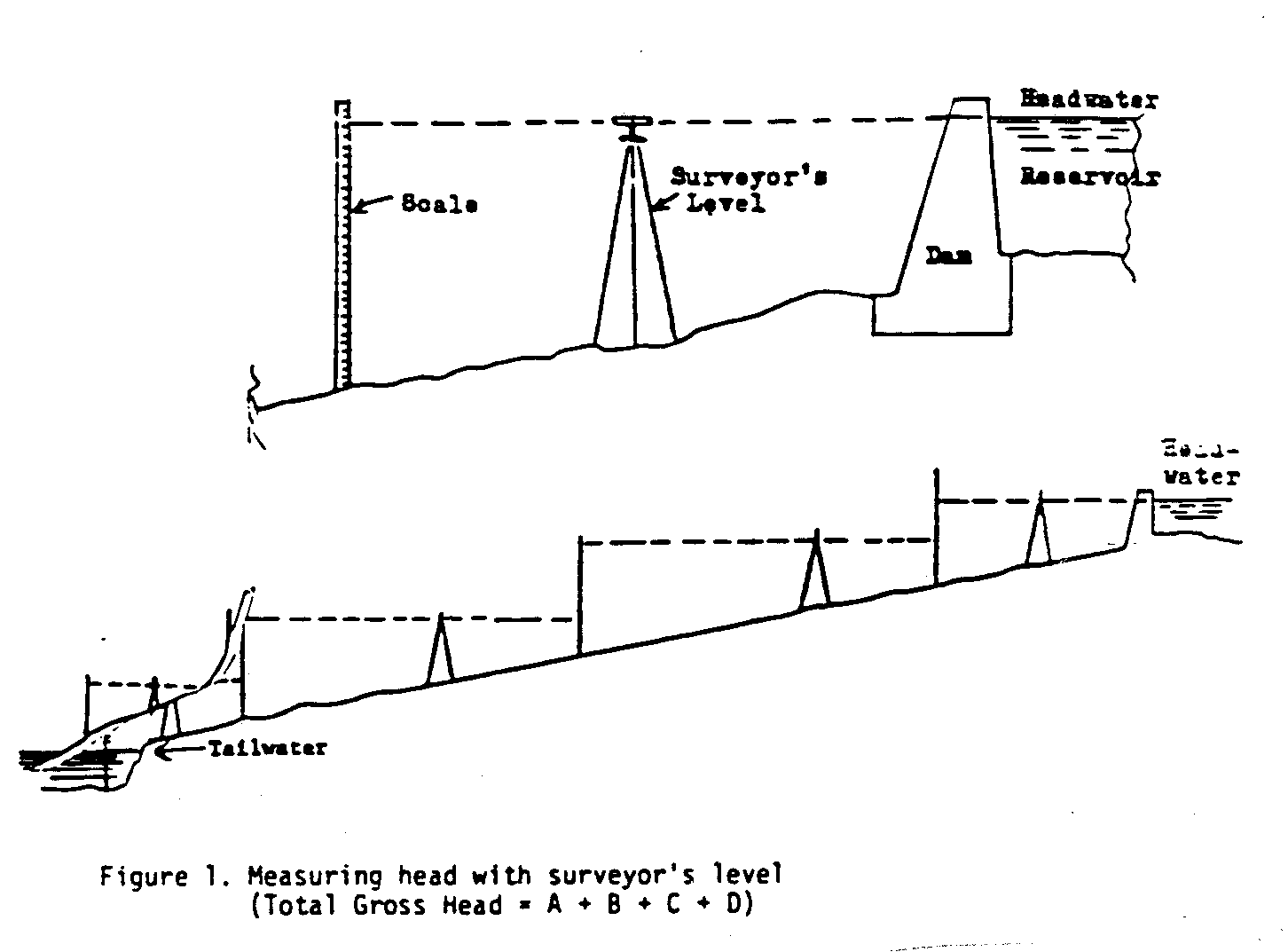
Figure 1). Water power is also very economical where a dam can be
lcd1x2.gif (486x486)
built into a small river with a relatively short (less than 100 feet)(1)
conduit (penstock) for conducting water to the water wheel (note
Figure 10). Development cost can be fairly high when such a dam and
lcd10x11.gif (600x600)

pipeline can provide a head of only 20 feet or less. Cost factors which
must be considered are:
1. Capital Expenditures
a. Design cost - can be relatively high for small plants.
b. Cost of Head Plants.
High for low-head plants where a dam and reservoir have to
be created.
Small for high-head plants with only an intake, a pipeline
and shed for machinery.
(1) A table for converting English units to metric units is given in
Appendix 2.
c. Riparian Rights - the rights of those whose property borders
on a body of water must be respected.
d. Construction Cost - including civil works and machinery.
e. Electrical Equipment - transformers, transmission lines, and
meters.
2. Operating Expenditures
a. Amortization charges and interest on capital expenditures.
b. Depreciation - for machinery, about 4% a year.
- for buildings, it can be as low as 1% a year.
c. Labor - operation and maintenance.
d. Repairs.
e. Taxes, insurance, and administration.
The safest method of evaluating and developing a small site is to
be guided by the following instructions for determining available
head, flow, and, therefore, power.
A Note of Caution: flow should be measured at a time when it is at
a minimum, i.e., during the dry season. Otherwise the plant will be
oversized.
The data obtained can be submitted through VITA to several manufacturers
of small turbines for preliminary quotations and recommendations. Turbine
manufacturers will furnish considerable advice and usually an outline drawing
of the entire project. Government publications for designing civil
works such as a dam are available from:
U.S. Government Printing Office Her Majesty's Stationery Office
Washington, D.C. 20402 and London, England
U.S.A.
These agencies will supply a list of publications on the subject.
II. BASIC DATA
A. Minimum flow in cubic feet or cubic meters per second.
B. Maximum flow to be utilized.
C. Available head in feet or meters.
D. Pipe line length required for obtaining desired head.
E. Site sketch with elevations, or topographical map with site sketched in.
F. Water condition, whether clear, muddy, sandy, acid, etc.
F. Soil condition, the velocity of the water and the size of the ditch or
channel for carrying it to the works depends on soil condition.
H. Minimum tailwater elevation at the powerhouse site must be given to
determine the turbine setting and type.
I. Air temperature, minimum and maximum.
III. POWER
The amount of power desired (useful power) should be determined in
advance. Power way be expressed in terms of horsepower or kilowatts. One
horsepower is equal to 0.7455 kilowatts. One kilowatt is about one and a
third horsepower. The required amount of power (gross power) is equal to
the useful power plus the losses inherent in any power scheme. It is
usually safe to assume that the net or useful power in the case of small
power installations will only be half of the available gross power due to
water transmission losses and the turbine and generator efficiencies. Some
power is lost when it is transmitted from the generator switchboard to
the place of application.
The GROSS POWER, the power available from the water, is determined by the
following formula:
In English Units:
Gross Power (horsepower)
Minimum Water Flow (cubic feet/second) X Gross Head(feet)
---------------------------------------------------------
8.8
In Metric Units:
Gross Power (Metric horsepower) = 1,000 Flow (cubic meters/second)
----- X Head(meters)
75
The NET POWER available at the turbine shaft is:
In English Units:
Net Power = Minimum Water Flow X Net Head X Turbine Efficiency (English)
-----------------------------
8.8
In Metric Units:
Net Power = Minimum Water Flow X Net Head X Turbine Efficiency (Metric)
-----------------------------
75/1,000
The NET HEAD is obtained by deducting the energy losses from the gross
head. These losses are discussed in section VI. A good assumption for
turbine efficiency, when it is not known, is 80%.
IV. MEASURING GROSS HEAD
(Either Method)
A. Method No. 1
1. Equipment
a. Surveyor's leveling instrument - consists of a spirit level
fastened parallel to a telescopic sight (note Figure 2).
lcd2x5.gif (285x285)

b. Scale - use wooden board approximately 12 feet in length
(note Figure 3).
lcd3x5.gif (285x285)

2. Procedure (note Figure 1)
lcd1x2.gif (600x600)
a. Surveyor's level on a tripod is placed down stream from the
power reservoir dam on which the headwater level is marked.
b. After taking a reading, the level is turned 180[degrees] in a
horizontal circle. The scale is placed downstream from it
at a suitable distance and a second reading is taken. This
process is repeated until the tailwater level is reached.
B. Method No. 2
This method is fully reliable, but is more tedious than Method No. 1
and need only be used when a surveyor's level is not available.
1. Equipment
a. Scale (note Figure 3).
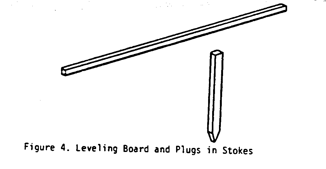
b. Board and wooden plug (note Figures 4 and 6).
lcd4x50.gif (285x285)
c. Ordinary carpenter's level (note Figure 5).
lcd5x6.gif (317x317)

2. Procedure (note Figure 6)
lcd6x7.gif (600x600)

a. Place board horizontally at headwater level and place level
on top of it for accurate leveling. At the downstream end
of the horizontal board, the distance to a wooden plug set
into the ground is measured with a scale.
b. The process is repeated step wise until the tailwater level
is reached.
V. MEASURING FLOW RATE
For power purposes, measurements should take place at the season of
lowest flow in order to guarantee full power at all times. Investigate
the stream flow history to ascertain that the minimum required flow is
that which has occurred for as many years as it is possible to determine.
An obvious point that has, nevertheless, been overlooked in the past is
this: if there have been years of drought in which flow rate was reduced
below the minimum required, other streams or sources of power may offer a
better solution.
A. Method No. 1
For small streams with a capacity of less than one cubic foot per
second, build a temporary dam in the stream, or use a "swimming
hole" created by a natural dam. Channel the water into a pipe and
catch it in a bucket of known capacity. Determine the stream flow
by measuring the time it takes to fill the bucket.
Stream Flow (cubic feet per second) = Volume of Bucket (cubic feet)/Filling Time (seconds)
B. Method No. 2
For medium streams with a capacity of more than one cubic foot per
second, the weir method can be used. The weir (see Figures 7 & 8)
lcd7x8.gif (600x600)

is made from boards, logs or scrap lumber. Cut a rectangular
opening in the center. Seal the seams of the boards and the sides
built into the banks with clay or sod to prevent leakage. Saw the
edges of the opening on a slant to produce sharp edges on the upstream
side. A small pond is formed upstream from the weir. When
there is no leakage and all water is flowing through the weir opening,
(1) place a board across the stream and (2) place another narrow board
level (use a carpenter's level) and perpendicular to the first. Measure
the depth of the water above the bottom edge of the weir with the help
of a stick on which a scale has been marked. Determine the flow from
Table I.
Table I
FLOW VALUE (Cubic Feet per Second)
Weir Width
------------------------------------------------------------
Overflow Height 3 feet 4 feet 5 feet 6 feet 7 feet 8 feet 9 feet
------------------------------------------------------------
1.0 inch .24 .32 .40 .48 .56 .64 .72
2 inches .67 .89 1.06 1.34 1.56 1.8 2.0
4 inches 1.9 2.5 3.2 3.8 4.5 5.0 5.7
6 inches 3.5 4.7 5.9 7.0 8.2 9.4 10.5
8 inches 5.4 7.3 9.0 10.8 12.4 14.6 16.2
10 inches 7.6 10.0 12.7 15.2 17.7 20.0 22.8
12 inches 10.0 13.3 16.7 20.0 23.3 26.6 30.0
C. Method No. 3
The float method (Figure 9) is used for larger streams. Although it
lcd9x10.gif (600x600)

is not as accurate as the previous two methods, it is adequate for
practical purposes. Choose a point in the stream where the bed is
smooth and the cross section is fairly uniform for a length of at
least 30 feet. Measure water velocity by throwing pieces of wood into
the water and measuring the time of travel between two fixed points,
30 feet or more apart. Erect posts on each bank at these points.
Connect the 2 upstream posts by a level wire rope (use a carpenter's
level). Follow the same procedure with the down stream posts. Divide
the stream into equal sections along the wires and measure the water
depth for each section. In this way, the cross-sectional area of
the stream is determined. Use the following formula to calculate the
flow:
Stream Flow (cubic feet per second) = Average Cross-Sectional Flow
Area(square feet) X Velocity (feet per second)
VI. MEASURING HEAD LOSSES
As noted in Section III, the "Net Power" is a function of the "Net
Head". The "Net Head" is the "Gross Head" less the "Head Losses".
Figure 10 shows a typical small water power installation. The head losses
lcd10x11.gif (600x600)
are the open-channel losses plus the friction loss from flow through the
penstock.
A. Open Channel Head Losses
The headrace and the tailrace in Figure 11 are open channels for
lcd11x12.gif (600x600)

transporting water at low velocities. The walls of channels made of
timber, masonry, concrete, or rock, should be constructed
perpendicularly. Design them so that the water level height is one half of
the width. Earth walls should be built at a 45[degrees] angle. Design them so
that the water level height is one half of the channel width at the
bottom. At the water level the width is twice that of the bottom.
The head loss in open channels is given in the nomograph in Figure 12.
lcd12x13.gif (600x600)

The friction effect of the material of construction is called "n". Various
values of "n" and the maximum water velocity, below which the walls of a
channel will not erode are given in Table II.
Table II
Maximum Allowable
Water Velocity
Material of Channel Wall (feet/second) Value of "n"
Fine grained sand 0.6 0.030
Coarse sand 1.2 0.030
Small stones 2.4 0.030
Coarse stones 4.0 0.030
Rock 25.0 (Smooth) 0.033 (Jagged) 0.045
Concrete with sandy water 10.0 0.016
Concrete with clean water 20.0 0.016
Sandy loam, 40% clay 1.8 0.030
Loamy soil, 65% clay 3.0 0.030
Clay loam, 85% clay 4.8 0.030
Soil loam, 95% clay 6.2 0.030
100% clay 7.3 0.030
Wood 0.015
Earth bottom with rubble sides 0.033
The hydraulic radius is equal to a quarter of the channel width, except
for earth-walled channels where it is 0.31 times the width at the bottom.
To use the nomograph, a straight line is drawn from the value of "n"
through the flow velocity to the reference line. The point on the reference
line is connected to the hydraulic radius and this line is extended
to the head-loss scale which also determines the required slope of the
channel.
B. Pipe Head loss and Penstock Intake
The trashrack in Figure 13 is a weldment consisting of a number of
lcd13x15.gif (600x600)

vertical bars held together by an angle at the top and a bar at the
bottom. The vertical bars must be spaced in such a way that the
teeth of a rake can penetrate the rack for removing leaves, grass
and trash which might clog up the intake. Such a trashrack can
easily be manufactured in the field or in a small welding shop.
Downstream from the trashrack, a slot is provided in the concrete
into which a timber gate can be inserted for shutting off the flow
of water to the turbine.
The penstock can be constructed from commercial pipe. The pipe
must be large enough to keep the head loss small. From the nomograph
(Figure 14) the required pipe size is determined. A straight line
lcd14x16.gif (600x600)

drawn through the water velocity and flow rate scales gives the
required pipe size and pipe head-loss. Head loss is given for a
100-foot pipe length. For longer or shorter penstocks, the actual
head loss is the head loss from the chart multiplied by the actual
length divided by 100. If commercial pipe is too expensive, it is
possible to make pipe from native material; for example, concrete
and ceramic pipe or hollowed logs. The choice of pipe material
and the method of making the pipe depend on the cost and availability
of labor and the availability of material. VITA can provide the
needed technical information.
VII. SMALL DAMS
A dam is necessary in most cases to direct the water into the channel
intake or to get a higher head than the stream naturally affords. A dam
is not required if there is enough water to cover the intake of a pipe or
channel at the head of the stream where the dam would be placed.
A dam may be made of earth, wood, concrete or stone. In building any
kind of a dam, all mud, vegetable matter and loose material must be removed
from the bed of the stream where the dam is to be placed. This usually is
not difficult since most small streams will cut their beds down close to
bed rock, hard clay or other stable formation.
A. Earth Dams
An earth dam may be desirable where concrete is expensive and timber
scarce. It must be provided with a separate spillway of sufficient
size to carry off excess water because water can never be allowed to
flow over the crest of an earth dam. If it does the dam will-erode and
be destroyed. A spillway must be lined with boards or with concrete
to prevent seepage and erosion. Still water is held satisfactorily by
earth but moving water is not. The earth will be worn away by it.
Figures 15 and 16 show a spillway and an earth dam. The crest of the
lcd15170.gif (600x600)

a roadway, with a bridge placed across the spillway.
NOTE: Building a dam will cause important environmental changes
both upstream and downstream. In addition, even a small dam creates
a potential flooding hazard once it is filled with water. CONSULT
A PROFESSIONAL CIVIL ENGINEER BEFORE BUILDING A DAM.
The greatest difficulty in earth-dam construction occurs in places where
the dam rests on solid rock. It is hard to keep the water from seeping
between the dam and the earth and finally undermining the dam. One way
of preventing seepage is to blast and clean out a series of ditches in
the rock, with each ditch about a foot deep and two feet wide extending
under the length of the dam. Each ditch should be filled with three
or four inches of wet clay compacted by stamping it. More layers of
wet clay can then be added and the compacting process repeated each
time until the clay is several inches higher than bedrock. The upstream
half of the dam, as shown in Figure 16 should be of clay or heavy clay
lcd16x18.gif (600x600)

soil, which compacts well and is impervious to water. The downstream
side should consist of lighter and more porous soil, which drains out
quickly and thus makes the dam more stable than if it were made
entirely of clay.
B. Crib Dams
The crib dam is very economical in timber country as it requires only
rough tree trunks, cut planking and stones. Four- to six-inch tree
trunks are placed two to three feet apart and spiked to others placed
across them at right angles. Stones fill the spaces between timbers.
The upstream side (face) of the dam, and sometimes the downstream side,
is covered with planks (see Figure 17). The face is sealed with clay
lcd17x19.gif (600x600)

to prevent leakage. Downstream planks are used as an apron to guide
the water which overflows the dam back into the stream bed. The dam
itself serves as a spillway in this case. The water coming over the
apron falls rapidly and it is necessary to line the bed below with
stones in order to prevent erosion. A section of a crib dam without
downstream planking is illustrated in Figure 18. The apron consists
lcd18x19.gif (600x600)

of a series of steps for slowing the water gradually.
Crib dams, as well as other types, must be embedded well into the
embankments and packed with impervious material such as clay or
heavy earth and stones in order to anchor them and to prevent
leakage. At the heel as well as at the toe of crib dams, longitudinal
rows of planks are driven into the stream bed. These are priming
planks which prevent water from seeping under the dam, and the also
anchor it. If the dam rests on rock, priming planks cannot and need
not be driven; but where the dam does not rest on rock they make it
more stable and watertight. These priming planks should be driven as
deep as possible and then spiked to the timber of the crib dam. The
lower ends of the priming planks are pointed as shown in Figure 19,
lcd19x20.gif (437x437)

and they must be placed one after the other as shown. Thus each
successive plank is forced, by the act of driving it, closer against
the preceding plank resulting in a solid wall. Any rough lumber may
be used. Chestnut and oak are considered to be the best material. The
lumber must be free from sap, and its size should be approximately
two inches by six inches. In order to drive the priming planks and
also the sheet piling of Figure 16, considerable force may be required.
lcd16x18.gif (600x600)
A simple pile driver as shown in Figure 20 will serve the
lcd20x20.gif (486x486)

purpose.
C. Concrete and Masonry Dams
Concrete and masonry dams more than 12 feet high should not be built
without the advice of a competent engineer with experience in this
special field. Dams of less height require knowledge of the soil
condition and bearing capacity as well as of the structure itself.
Figure 21 shows a stone dam which also serves as a spillway. It can
lcd21x21.gif (600x600)

be up to ten feet in height. It is made of rough stones. The layers
should be bound by concrete. The dam must be built down to a solid
and permanent footing to prevent leakage and shifting. The base of
the dam should have the same dimension as its height to give it
stability.
Small concrete dams (Figure 22) should have a base with a thickness
lcd22x22.gif (486x486)

50% greater than height. The apron is designed to turn the flow
slightly upwards to dissipate the energy of the water and protect
the downstream bed from eroding.
VIII. WATER TURBINES
The manufacturers of hydraulic turbines for small plants can usually
quote on a complete packaged unit, including the generator, governor and
switch gear. Water turbines for small power developments may be purchased
(see Table III) or made in the field, if a small machine and weld shop is
available.
A centrifugal pump may be used as a turbine wherever it is technically
possible. Its cost is about one-third the cost of a hydraulic turbine. But
it may be poor economics to use a centrifugal pump because it is less
efficient than a turbine and will have other disadvantages.
A water power unit can produce either direct current (D.C.) or
alternating current (A.C.) electricity.
Two factors to consider in deciding whether to install an A.C. or D.C.
power unit are (1) the cost of regulating the flow of water into the turbine
for A.C. and (2) the cost of converting motors to use D.C. electricity.
Flow Regulation
The demand for power will vary from time to time during the day. With
a constant flow of water into the turbine, the power output will sometimes
be greater than the demand for power. Therefore, either excess power must
be stored or the flow of water into the turbine must be regulated according
to the demand for power.
In producing A.C., the flow of water must be regulated because A.C.
cannot be stored. Flow regulation requires governors and complex valve-type
shut-off devices. This equipment is expensive; in a small water
power site, the regulating equipment would cost more than a turbine and
generator combined. Furthermore, the equipment for any turbine used for
A.C. must be built by experienced water-turbine manufacturers and serviced
by competent consulting engineers.
The flow of water to a D.C. producing turbine, however, does not
have to be regulated. Excess power can be stored in a storage battery.
Direct-current generators and storage batteries are low in cost because
they are mass-produced.
To summarize: In producing A.C., the flow of water into the turbine
must be regulated; this requires costly and complex equipment. In producing
D.C., regulation is not necessary, but storage batteries must be
used.
Converting Motors for D.C.
D.C. power is just as good as A.C. for producing electric light and
heat. But for electrical appliances, from farm machinery to household
appliances, the use of D.C. power can involve some expense. When such
appliances have A.C. motors, D.C. motors must be installed. The cost of
doing this must be weighed against the cost of flow regulation needed for
producing A.C.
Table III
Small Hydraulic Turbines
Types
Impulse Michell Centrifugal Pump
or or Used as
Pelton Banki Turbine
Head Range 50 to 1000 3 to 650 Available
(feet)
for
Flow Range 0.1 to 10 0.5 to 250
(cubic feet per second) any
Application high head medium head desired
Power 1 to 500 1 to 1000 condition
(horsepower)
Cost per Kilowatt low low low
Manufacturers James Leffel & Co. Ossberger- Any reputable
Springfield, Ohio Turbinenfabrik dealer or
U.S.A. 45501 8832 Weissenbura manufacturer
Drees & Co. Bayern, Germany
Werl. Germany Can be do-it-your-
Officine Buhler self project if small
Taverne, Switzerland weld and machine
shops are available
A. Impulse Turbines
Impulse turbines are used for high heads and low flow rates. They
are the most economical turbine because the high head gives them high
speed and their size and weight per horsepower is small. Construction
costs of intake and power house are also small. A very simplified
version is shown in Figures 23 and 24.
lcd23240.gif (600x600)

The Michell (or Banki) turbine is simple in construction and may be
the only type of water turbine which can be locally built. Welding
equipment and a small machine Shop like those often used to repair
farm machinery and automotive parts are all that is necessary.
The two main parts of the Michell turbine are the runner and the
nozzle. Both are welded from plate steel and require some machining.
Figures 25 and 26 show the arrangement of a turbine of this type for
lcd25270.gif (600x600)

generator with a belt drive. Because the construction can be a DO-IT-YOURSELF
project, formulas and design details are given for a runner of
12" outside diameter. This size is the smallest which is easy to
fabricate and weld. It has a wide range of application for all small
power developments with head and flow suitable for the Michell turbine.
Different heads result in different rotational speeds. The proper belt-drive
ratio gives the correct generator speed. Various amounts of water
determine the width of the nozzle ([B.sub.1], Figure 26) and the width of the
lcd26x28.gif (600x600)

runner ([B.sub.2], Figure 26). These widths may vary from 2 inches to 14 inches.
No other turbine is adaptable to as large a range of flow.
The water passes through the runner twice in a narrow jet before discharge
into the tailrace. The runner consists of two side plates, each 1/4"
thick with hubs for the shaft attached by welding, and from 20 to 24
blades. Each blade is 0.237" thick and cut from 4" standard pipe.
Steel pipe of this type is available virtually everywhere. A pipe of
suitable length produces four blades. Each blade is a circular segment
with a center angle of 72 degrees. The runner design, with dimensions
for a foot-long runner, is shown in Figure 27; and Figure 28 gives the
lcd27290.gif (600x600)

for other size runners. Upstream from the nozzle discharge
opening of 1 1/4", the shape of the nozzle can be made to suit penstock
pipe conditions.
To calculate the principal turbine dimension:
[B.sub.1] = Nozzle Width (inches) = 210 X Flow (cubic feet per second)
-----------------------------------------------------------
Runner Outside Diameter (inches) X [square root]Head (feet)
[B.sub.2] = Runner Width between Discs = [B.sub.1] + 1/2 to 1"
Rotational Speed (revolutions per minute) = 73.1 X [square root] Head (feet)
--------------------------------
Runner Outside Diameter (feet)
The efficiency of the Michell turbine is 80% or greater and therefore
suitable for small power installations. Flow regulation and governor,
control of the flow can be effected by using a center-body nozzle
regulator (a closing mechanism in the shape of a gate in the nozzle).
This is expensive because of governor costs. It is, however, needed
for running an alternating-current generator.
The application of Figures 25 and 26 is a typical example. For high
heads the Michell turbine is connected to a penstock with a turbine
inlet valve. This requires a different type of arrangement from the
one shown here. As mentioned before, the Michell turbine is unique
because its [B.sub.1] and [B.sub.2] widths can be altered to suit power-site traits
of flow rate and head. This, besides simplicity and low cost, makes
it the most suitable of all water turbines for small power developments.
C. Centrifugal Pumps and Propeller-Type Pumps
The use of centrifugal pumps or propeller-type pumps as turbines
should be explored before all other alternatives, provided that
direct-current electricity can be used (See Figures 29 and 30).
lcd29320.gif (600x600)

cost and are available in many sizes. Manufacturers can quote
the proper unit if head and flow are given.
They can be used to produce alternating current also, but with increased
cost. In this case, a butterfly valve is used as the turbine-inlet
valve; and the valve can be regulated by a small water-turbine
governor.
The help of an engineer should be sought in modifying these pumps for
use as turbines.
IX. WATER WHEELS
Water wheels date back to biblical times but are far from obsolete.
They have certain advantages which should not be overlooked. They are
more economical for small power requirements than water turbines in some
cases. It is possible to make a water wheel for power requirements up to
10 horsepower in places where there are no elaborate manufacturing
facilities.
Water wheels are attractive especially where fluctuations in flow rate
are large. Speed regulation is not practical -- therefore, water wheels are
used primarily to drive machinery which can take large fluctuations in
rotational speed. They operate between 2 and 12 revolutions per minute
and require gearing and belting (with inherent friction loss) to run most
machines. Thus, they are most useful for slow-speed applications, e.g.,
flour mills, some agricultural equipment, and some pumping operations.
A water wheel, because of its rugged design, requires less care than
a turbine does. It is self-cleaning, and, therefore, need not be protected
from debris (leaves, grass and stones). The two main types of
water wheels are the overshot and the undershot.
A. Overshot Water Wheel
The overshot water wheel way be used with heads of 10 to 30 feet, and
flow rates from one to 30 cubic feet per second.
The water is guided to the wheel in a timber or metal flume at a
water velocity of approximately 3 feet per second. A gate at the
end of the flume controls the flow to the wheel and the jet velocity,
which should be from 6 to 10 feet per second. To obtain this velocity,
the head ([H.sub.1] in Figure 31) should be one to two feet. Wheel width
lcd31x34.gif (600x600)

depends on he amount of water to be used. The discharge will be one
to two cubic feet per-second for a flume width of one foot. Wheel
width must exceed flume width by about one foot because of jet
expansion. The efficiency of a well-constructed overshot water wheel
can be 60% to 80%.
B. Undershot Water Wheel
The undershot water wheel (Figure 32) should be used with heads of 1.5
lcd32x35.gif (600x600)

to 10 feet and flow rates from 10 to 100 cubic feet per second. Wheel
diameter should be 3 to 4 times the head -- wheel diameters between 6
and 30 feet. Rotational speed should be 2 to 12 revolutions per minute,
with the higher speed applying to the smaller wheels. For each foot
of wheel width, the flow rate should be between 3 and 10 cubic feet
per second. The wheel dips from one to three feet into the water.
Efficiency is in the range of 60% to 75%.
X. EXAMPLES
Mission Hospital
1. Requirements: 10 kilowatt light and power plant.
2. 10 kilowatts is 13 1/3 horsepower.
3. The gross power required is then about 27 horsepower.
4. A stream in hilly territory can be dammed up and the water
channeled through a ditch 112 mile long to the power plant site.
5. A penstock 250 feet long will take the water to the turbine.
6. The total difference in elevation is 140 feet.
7. Available minimum flow rate: 1.8 cubic feet/second.
8. The soil in which the ditch is to be dug permits a water velocity
of 1.2 feet per second.
9. Table II, Section VI gives n= 0.030
10. Area of flow in the ditch = 1.8/1.2 = 1.5 square feet.
11. Bottom width = 1.5 feet.
12. Hydraulic radius = 0.31 X 1.5 = 0.46 feet.
13. Figure 8 shows that this results in a fall and head loss of 1.7 feet
lcd8x8.gif (486x486)

for 1,000 feet. The total for the half-mile (2,64C feet) ditch is
4.5 feet.
14. The fall that is left through the penstock is then: 140-4.5 = 135.5
feet. Figure 10 gives 5.7 inches as the required penstock diameter
lcd10x11.gif (600x600)
for 1.8 cubic feet per second flow at 10 feet per second velocity.
15. Head loss in the penstock is 10 feet for 100 feet of length and
25 feet for the total length of 250 feet.
16. For the water tubine:
Net Head = 135.5-25 = 110.5 feet
17. Power produced by the turbine at 80% efficiency:
Net Power = Minimum water flow X net head/8.8 X Turbine Efficiency
=1.8 X 110.5/8.8 X .80 = 18 horsepower
18. Consult Table III. The cost of a pump or turbine for a particular
situation can only be learned by writing to the various manufacturers.
VITA engineers can step in here, lay out the physical
arrangement and compile a list of necessary mechanical and
electrical components to the best advantage of the field worker.
Appendix 1
AVAILABILITY OF MANUFACTURED TURBINES
Small hydraulic turbines and even more the governors for regulating
these turbines are difficult to obtain because the demand for these products
has diminished to a considerable extent in the last twenty years. And
manufactured water wheels are completely off the market. Of the remaining
number of manufacturers of small turbines and governors only one exists in
the United States, and two are known by the author to exist in Europe.
The James Leffel & Company is located in Springfield, Ohio. Their
booklet, Leffel Pamphlet "A". Hints on the Development of Small Water
Power, is available on request. It is a very useful supplement to the
information in this manual. Its description of Leffel's small vertical
Samson turbine is very complete. This turbine is available in sizes from
3 to 29 horsepower. The company maintains an engineering department
which stands ready to assist in planning and design of the entire installation.
This company also manufactures a complete unit called Hoppes Hydroelectric
Unit, which is useful in isolated locations where the demand is
small. It comes in sizes of I to 10 kilowatts. A Leffel bulletin
describing this unit gives complete instructions on submitting the
information necessary for ordering it.
The Michell (or Banki) turbine is manufactured exclusively by the
Ossberger-Turbinenfabrik of Weissenburg, Bavaria, Germany. This turbine
is made in sizes ranging from 1 to 1000 horsepower. The company has an
impressive record of installations, many in less-developed countries.
Ossberger-Turbinenfabrik is very responsive to requests for information.
It furnishes without charge a considerable amount of data, translated
into English. The simple design of the Michell turbine makes it a
favorite for remote regions and is priced lower than corresponding
Francis and impulse type turbines. Its governor, developed by Ossberger,
is also very reasonably priced.
A third company which manufactures turbines and governors for turbines
but does not sell packaged units, including the electrical equipment, is
the Officine Buehler, Taverne. Canton Ticino. Switzerland. They are in
the small turbine field, and they manufacture all types except Michell.
Their workmanship is of the highest quality, and their engineering is
superb. Like the other companies, they assist prospective customers in
planning their installations.
Appendix 2
CONVERSION TABLES
Units of Length
1 Mile = 1760 Yards = 5280 Feet
1 Kilometer = 1000 Meters = 0.6214 Mile
1 Mile = 1.607 Kilometers
1 Foot = 0.3048 Meter
1 Meter = 3.2808 Feet = 39.37 Inches
1 Inch = 2.54 Centimeters
1 Centimeter = 0.3937 Inch
Units of Area
1 Square Mile = 640 Acres = 2.5899 Square Kilometers
1 Square Kilometer = 1,000.000 Sq. Meters = 0.3861 Square Mile
1 Acre = 43.560 Square Feet
1 Square Foot = 144 Square Inches = 0.0929 Square Meter
1 Square Inch = 6.452 Square Centimeters
1 Square Meter = 10.764 Square Feet
1 Square Centimeter = 0.155 Square Inch
Units of Volume
1.0 Cubic Foot = 1728 Cubic Inches = 7.48 U.S. Gallons
1.0 British Imperial Gallon = 1.2 U.S. Gallons
1.0 Cubic Meter = 35.314 Cubic Feet = 264.2 U.S. Gallons
1.0 Liter = 1000 Cubic Centimeters = 0.2642 U.S. Gallons
Units of Weight
1.0 Metric Ton = 1000 Kilograms = 2204.6 Pounds
1.0 Kilogram = 1000 Grams = 2.2046 Pounds
1.0 Short Ton = 2000 Pounds
CONVERSION TABLES
Units of Pressure
1.0 Pound per square inch = 144 Pound per square foot
1.0 Pound per square inch = 27.7 Inches of Water(*)
1.0 Pound per square inch = 2.31 Feet of Water(*)
1.0 Pound per square inch = 2.042 Inches of Mercury(*)
1.0 Atmosphere = 14.7 Pounds per square inch (PSI)
1.0 Atmosphere = 33.95 Feet of Water(*)
1.0 Foot of Water = 0.433 PSI = 62.355 Pounds per square foot
1.0 Kilogram per square centimeter = 14.223 pounds per square inch
1.0 pound per square inch = 0.0703 kilogram per square centimeter
(*) at 62 degrees Fahrenheit (16.6 degrees Celsius)
Units of Power
1.0 Horsepower (English) = 746 Watt = 0.746 Kilowatt (KW)
1.0 Horsepower (English) = 550 foot pounds per second
1.0 Horsepower (English) = 33,000 foot pounds per minute
1.0 Kilowatt (KW) = 1000 Watt = 1.34 Horsepower (HP) English
1.0 Horsepower (English) = 1.0139 Metric Horsepower (cheval-vapeur)
1.0 Metric Horsepower = 75 Meter X Kilogram/Second
1.0 Metric Horsepower = 0.736 Kilowatt = 736 Watt
Appendix 3
BIBLIOGRAPHY
General Texts and Handbooks
Brown, J. Guthrie ed, Hydro Electric Engineering Practice. New York:
Gordon & Breach, 1958; London: Blackie and Sons, Ltd., 1958. A
very complete treatise covering the entire field of hydroelectric
engineering. Three volumes. v. 1 Civil Engineering $50.00 U.S.
v. 2 Mechanical and Electrical Engineering $30.00 U.S.
v. 3 Economics, Operation and Maintenance ($25.00 U.S.)
Creager, W. P. and Justin, J. D. Hydro Electric Handbook. 2d ed.
New York: John Wiley and Son, 1950. A most complete handbook
covering the entire field. Especially good for reference.
($18.50 U.S.)
Davis, Calvin V. Handbook of Applied Hydraulics. 2d ed. New York:
McGraw-Hill, 1952. A comprehensive handbook covering all phases
of applied hydraulics. Several chapters are devoted to hydroelectric
application. ($23.50 U.S.)
Paton, T. A. L. Power from Water. London: Leonard Hill, 1961. A
concise general survey of hydroelectric practice in abridged form.
($8.50 U.S.)
Zerban, A. H. and Nye, E.P. Power Plants. 2d ed. Scranton, Penn.:
International Text Book Co., 1952. Chapter 12 gives a concise
presentation of hydraulic power plants. ($8.00 U.S.)
The Banki Turbine
Haimerl, L. A., "The Cross Flow Turbine," Water Power (London), January
1960. Reprints available from Ossberger Turbinenfabrik, 8832 Weissenburg,
Bayern, Germany. This article describes a type of water turbine
which is being used extensively in small power stations, especially
in Germany.
Mockmore, C. A. and Merryfield, F., The Banki Water Turbine. Corvallis,
Ore.: Oregon State College Engineering Experiment Station Bulletin
No. 25, February 1949. 40c. A translation of a paper by Donat Banki.
A highly technical description of this turbine, originally invented
by Michell, together with the results of tests.
Small Michell (Banki) Turbine. Arlington, Virginia: Volunteers in
Technical Assistance (VITA), 1979.
Appendix 4
THE AUTHOR AND REVIEWERS
Hans W. Hamm, a VITA Volunteer, was a consultant on small water
power developments for twenty years with a Pennsylvania manufacturer
of water wheels and small turbines. He earned a degree in mechanical
engineering from the State Technical University of Braunschweig in his
native Germany. He retired in 1966 from the York, Pennsylvania, works
of Allis-Chalmers.
***
Other VITA Volunteers have helped in producing this manual: Morton
Rosenstein, public relations and market research manager at Ionics, Inc.,
Watertown, Massachusetts, edited the entire manual.
Harry Wiersoma, consulting engineer of Knoxville, Tennessee, made
many helpful suggestions based on more than fifty years' experience in
hydraulic engineering. He also wrote the preface for the manual and
prepared the bibliography.
Dr. John J. Cassidy, associate professor of civil engineering,
University of Mitsouri, and Robert H. Emerick, consulting engineer
of Charleston, South Carolina, both reviewed the manual for technical
accuracy.
Ian D. Burnet, projects officer of the Department of Trade and
Industry, Port Moresby, Papua, New Guinea, reviewed the book from the
point of view of the eventual user, the community development leader.
***
The manual was also reviewed by Jeffrey Ashe and John Brandi,
Peace Corps Volunteers who were working on a project to develop a small
water power site in Loja, Ecuador, by Ossberger Turbinenfabrik,
Weissenburg (Bayern), Germany and by James Leffel & Company,
Springfield, Ohio.
Appendix 5
DATA SHEET
This form is given as a guide to help you collect the
information a VITA engineer would need to help you plan a small
water power site.
TO: Volunteers in Technical Assistance
1600 Wilson Boulevard, Suite 500
Arlington, Virginia 22209 USA
1. Minimum flow of water available in cubic feet per second
(or cubic meters) per second. __________________
2. Maximum flow of water available in cubic feet per second
(or cubic meters) per second. __________________
3. Head or fall of water in feet (or meters) __________________
4. Length of pipe line in feet (or meters) needed to get the
required head. __________________
5. Describe water condition (clear, muddy, sandy, acid)
__________________
6. Describe soil condition (see Table II) __________________
7. Minimum tailwater elevation in feet (or meters)_________________
8. Approximate area of pond above dam in acres (or square
kilometers). __________________
9. Approximate depth of the pond in feet (or meters)_______________
10. Distance from power plant to where electricity will be
used in feet (or meters). __________________
11. Approximate distance from dam to power plant __________________
12. Minimum air temperature. __________________
13. Maximum air temperature. __________________
14. Estimate power to be used. __________________
15. ATTACH SITE SKETCH WITH ELEVATIONS, OR TOPOGRAPHICAL MAP WITH
SITE SKETCHED IN.
Date_______________ Name__________________ _____________
Address_______________ _____________
See reverse for guide in _______________ _____________
collecting further helpful _____________________________
information.
DATA SHEET - 2
The following questions cover information which, although
not necessary in starting to plan a water power site, will
usually be needed later. If it can possibly be given early in
the project, this will save time later.
1. Give the type, power and speed of the machinery to be
driven and indicate whether direct, belt or gear drive is
desired or acceptable.
2. For electric current, indicate whether direct current is
acceptable or alternating current is required. Give the
desired voltage, number of phases and frequency
3. Say whether manual flow regulation can be used (with D.C.
and very small A.C. plants) or if regulation by an automatic
governor is needed.
Appendix 6
DECISION MAKING WORK SHEET
If you are using this guide in a development effort, collect as
much information as possible and if you need assistance with the
project, write VITA. A report on your experiences and the uses of
this manual will help VITA both improve the book and aid other
similar efforts.
Volunteers in Technical Assistance
1600 wilson Boulevard, Suite 500
Arlington, Virginia 22209, USA
CURRENT USE AND AVAILABILITY
o Describe current agricultural and domestic practices that rely
on water. What are the sources of water and how are they used?
o What water power sources are available? Are they small but
fast-flowing? Large but slow-flowing? Other characteristics?
o What is water used for traditionally?
o Is water harnessed to provide power for any purpose? If so,
what and with what positive or negative results?
o Are there dams already built in the area? If so, what have been
the effects of the damming? Note particularly any evidence of
sediment carried by the water--too much sediment can create a
swamp.
o If water resources are not harnessed, what seem to be the
limiting factors? Does cost seem prohibitive? Does the lack of
knowledge of water power potential limit its use?
NEEDS AND RESOURCES
o Based on current agricultural and domestic practices, what
seems to be the area of greatest need? Is power needed to run
simple machines such as grinders, saws, pumps?
o Given available water power sources, which ones seem to be
available and most useful? For example, one stream that runs
quickly year around and is located near the center of agricultural
activity may be the only feasible source to tap for
power.
o Define water power sites in terms of their inherent potential
for power generation.
o Are materials for constructing water power technologies available
locally? Are local skills sufficient? Some water power
applications demand a rather high degree of construction skill.
o How much skilled labor is necessary for construction and
maintenance? What kinds of skills are available locally? Can
you meet the need? Do you need to train people?
o Some aspects of turbine construction require someone with
experience in metalworking and/or welding. Is this skill
available?
o Waterwheel construction may require woodworkers. Are they
available?
o Is help available for dam building? Surveying? Determining
environmental impacts?
o Do a cost estimate of the labor, parts, and materials needed.
o How will the project be funded?
o What is your schedule? Are you aware of holidays and planting
or harvesting seasons, which may affect timing?
o How will you arrange to spread information on and promote use
of the technology?
IDENTIFY POTENTIAL
o Is more than one water power technology applicable? Remember to
look at all the costs. While one technology appears to be much
more expensive in the beginning, it could work out to be less
expensive after all costs are weighed.
o Are there choices to be made between a waterwheel and a
windmill, for example, to provide power for grinding grain?
Again weigh all the costs: economics of tools and labor, operation
and maintenance, social and cultural dilemmas.
o Are there local skilled resources to introduce water power
technology? Dam building and turbine construction should be
considered carefully before beginning work. Besides the higher
degree of skill required in turbine manufacture (as opposed to
waterwheel construction), these water power installations tend
to be more expensive.
o Where the need is sufficient and resources are available, consider
a manufactured turbine and a group effort to build the
dam and install the turbine.
o Is there a possibility of providing a basis for small business
enterprise?
FINAL DECISION
o How was the final decision reached to go ahead--or not go
ahead--with this project? Why?
Appendix 7
RECORD KEEPING WORK SHEET
Detailed records of project implementation are helpful to ongoing
project management and to other people who may be involved in
similar efforts elsewhere.
CONSTRUCTION
Photographs of the construction and installation process, as well
as the finished result, are helpful. They add interest and detail
that might be overlooked in the narrative.
A report on the construction process should include much very
specific information. This kind of detail can often be monitored
most easily in charts (such as the one below). <see report 1>
lcdrp10.gif (437x437)

Some other things to record include:
o Specification of materials used in construction.
o Adaptations or changes made in design to fit local conditions.
o Equipment costs.
o Time spent in construction--include volunteer time as well as
paid labor; full- or part-time.
o Problems--labor shortage, work stoppage, training difficulties,
materials shortage, terrain, transport.
OPERATION
Keep log of operations for at least the first six weeks, then
periodically for several days every few months. This log will
vary with the technology, but should include full requirements,
outputs, duration of operation, training of operators, etc.
Include special problems that may come up--a damper that won't
close, gear that won't catch, procedures that don't seem to make
sense to workers, etc.
MAINTENANCE
Maintenance records enable keeping track of where breakdowns
occur most frequently and may suggest areas for improvement or
strengthening weakness in the design. Furthermore, these records
will give a good idea of how well the project is working out by
accurately recording how much of the time it is working and how
often it breaks down. Routine maintenance records should be kept
for a minimum of six months to one year after the project goes
into operation. <see report 2>
lcdrp2.gif (437x437)

SPECIAL COSTS
This category includes damage caused by weather, natural disasters,
vandalism, etc. Pattern the records after the routine
maintenance records. Describe for each separate incident:
o Cause and extent of damage.
o Labor costs of repair (like maintenance account).
o Material costs of repair (like maintenance account).
o Measures taken to prevent recurrence.
========================================
========================================
WATER POWER SITES
BY
HANS W. HAMM
VITA
1600 Wilson Boulevard, Suite 500
Arlington, Virginia 22209 USA
Tel: 703/276-1800 . Fax 703/243-1865
Internet: pr-info@vita.org
LOW COST DEVELOPMENT OF
SMALL WATER POWER SITES
HANS W. HAMM
a VITA publication
OTHER MANUALS OF INTEREST FROM VITA
Overshot Water-Wheel: Design and Construction Manual
Small Michell (Banki) Turbine
Hydraulic Ram
Environmentally Sound Small-Scale Water Projects:
Guidelines for Planning
(CODEL/VITA)
Environmentally Sound Small-Scale Energy Projects:
Guidelines for Planning
(CODEL/VITA)
For free catalogue of these and other VITA publications, write
to:
VITA Publications Services
Volunteers in Technical Assistance
1600 Wilson Boulevard, Suite 500
Arlington, Virginia 22209 USA
ABOUT VITA
Volunteers in Technical Assistance (VITA) is a
private, nonprofit,international development
organization. It makes available to individuals
and groups in developing countries a variety of
information and technical resources aimed at
fostering self-sufficiency--needs assessment and
program development support; by-mail and on-site
consulting services; information systems training.
Vita promotes the use of appropriate small-scale
technologies, especially in the area of
renewable energy. VITA's extensive documentation
center and worlwide roster of volunteer technical
experts enable it to respond to thousands of technical
inquiries each year. It also publishes a
quarterly newsletter and a variety of technical
manuals and bulletins.
VITA
VOLUNTEERS
IN TECHNICAL
ASSISTANCE
ISBN 0-86619-014-7
TABLE OF CONTENTS
Preface
I. Introduction
II. Basic Data
III. Power
IV. Measuring Gross Head
V. Measuring Flow Rate
VI. Measuring Head Losses
VII. Small Dams
VIII. Water Turbines
IX. Water Wheels
X. Example
Tables
I Flow Value
II Maximum Velocity & Friction Coefficient
Appendixes
1. Availability of Manufactured Turbines
2. Conversion Tables
3. Bibliography
4. The Author and Reviewers
5. Data Sheet
6. Decision Making Work Sheet
7. Record Keeping Work Sheet
PREFACE
During the last several years of answering individual requests from
Peace Corps and other community development workers, VITA has come to
realize the great need for a manual on small hydroelectric power development.
VITA is an international association of more than 5,000 scientists,
engineers, businessmen and educators who volunteer their talent and
spare time to help people in developing areas with their technical
problems. The Volunteers are from the United States and 100 other
countries.
The difficulty of communication has proved extreme in answering requests
concerning the feasibility of a small hydro plant as a source of
power, as compared with a diesel. The value of a manual written in simple
terms is readily apparent.
The present manual has been prepared to fill this need. It should
enable the reader to assess the possibility and desirability of installing
a small hydroelectric power plant, select the type of machinery most
suitable for installation, and order turbine and generating equipment.
It should also serve as a guide in actual construction and installation.
When further guidance is needed. VITA can put the reader in touch with
expert VITA Volunteers.
The manual begins by describing in simple language the steps necessary
to measure the head (the height of a body of water, considered as causing
pressure) and flow of the water supply, and gives data for computing the
amount of power available. Next it describes the construction of a small
dam and points out safety precautions necessary in designing and building
such structures. Following this is a discussion of turbines and water
wheels. Guide lines are given for making the right choice for a particular
site. In this connection, ready-made units are available from
such reliable manufacturers as James Leffel & Company in the United States
and Ossberger-Turbinenfabrik in Germany. Both companies give excellent
service in advising prospective purchasers.
This section of the manual also describes in detail how to make a
Michell (or Banki) turbine in a small machine shop with welding facilities,
from usually available pipe and other stock material. However,
the hazards accompanying the manufacture of so delicate a machine by
do-it-yourself methods, and the difficulty of achieving high efficiency
Should warn the ambitious amateur to consider the obvious alternative
of securing advice from a reliable manufacturer before attempting to
build his own. Table 3 gives information on the availability of manufactured
units. Electric generator equipment is standardized and
readily available.
Appendix 1 gives detailed information on manufacturers of turbines.
Appendix 2 is a chart for converting English units of measure to metric
units. English units are used in the text.
Finally, for those who are interested in pursuing the subject further
and who have the engineering background to understand technical treatises,
a bibliography in Appendix 2 describes textbooks and handbooks available
in English in the United States and England.
Harry Wiersema
I. INTRODUCTION
A. Alternatives
Flowing water tends to generate automatically a picture of "free"
power in the eyes of the observer. But there is always a cost to
producing power from water sources. The cost of developing low-output
water power sites should be checked against available alternatives,
such as:
1. Electric Utility - wherever transmission lines can furnish unlimited
amounts of reasonably priced electric current, it is
usually uneconomical to develop small and medium-sized sites.
2. Generators - diesel engines and internal-combusion engines may
use a variety of fuels, for example, oil, gasoline, or wood. In
general, the capital expenditure for this type of power plant is
low compared to a hydro-electric plant. Operating costs, on the
other hand, are very low for hydro-electricity and high for
generated power.
3. Solar Heat - extensive experimental work has been done on the
utilization of solar heat. Equipment now available may be less
costly than water power development in regions with long hours
of intense sunshine.
B. Evaluation
For isolated communities in countries where the cost of coal and oil
is high and access to transmission lines is limited or non-existent,
development of even the smallest water power site may be worthwhile.
Particularly favorable is the situation where the head (the height of
a body of water, considered as causing pressure) is relatively high,
and for this reason a fairly inexpensive turbine can be used (note
Figure 1). Water power is also very economical where a dam can be
lcd1x2.gif (486x486)
built into a small river with a relatively short (less than 100 feet)(1)
conduit (penstock) for conducting water to the water wheel (note
Figure 10). Development cost can be fairly high when such a dam and
lcd10x11.gif (600x600)
pipeline can provide a head of only 20 feet or less. Cost factors which
must be considered are:
1. Capital Expenditures
a. Design cost - can be relatively high for small plants.
b. Cost of Head Plants.
High for low-head plants where a dam and reservoir have to
be created.
Small for high-head plants with only an intake, a pipeline
and shed for machinery.
(1) A table for converting English units to metric units is given in
Appendix 2.
c. Riparian Rights - the rights of those whose property borders
on a body of water must be respected.
d. Construction Cost - including civil works and machinery.
e. Electrical Equipment - transformers, transmission lines, and
meters.
2. Operating Expenditures
a. Amortization charges and interest on capital expenditures.
b. Depreciation - for machinery, about 4% a year.
- for buildings, it can be as low as 1% a year.
c. Labor - operation and maintenance.
d. Repairs.
e. Taxes, insurance, and administration.
The safest method of evaluating and developing a small site is to
be guided by the following instructions for determining available
head, flow, and, therefore, power.
A Note of Caution: flow should be measured at a time when it is at
a minimum, i.e., during the dry season. Otherwise the plant will be
oversized.
The data obtained can be submitted through VITA to several manufacturers
of small turbines for preliminary quotations and recommendations. Turbine
manufacturers will furnish considerable advice and usually an outline drawing
of the entire project. Government publications for designing civil
works such as a dam are available from:
U.S. Government Printing Office Her Majesty's Stationery Office
Washington, D.C. 20402 and London, England
U.S.A.
These agencies will supply a list of publications on the subject.
II. BASIC DATA
A. Minimum flow in cubic feet or cubic meters per second.
B. Maximum flow to be utilized.
C. Available head in feet or meters.
D. Pipe line length required for obtaining desired head.
E. Site sketch with elevations, or topographical map with site sketched in.
F. Water condition, whether clear, muddy, sandy, acid, etc.
F. Soil condition, the velocity of the water and the size of the ditch or
channel for carrying it to the works depends on soil condition.
H. Minimum tailwater elevation at the powerhouse site must be given to
determine the turbine setting and type.
I. Air temperature, minimum and maximum.
III. POWER
The amount of power desired (useful power) should be determined in
advance. Power way be expressed in terms of horsepower or kilowatts. One
horsepower is equal to 0.7455 kilowatts. One kilowatt is about one and a
third horsepower. The required amount of power (gross power) is equal to
the useful power plus the losses inherent in any power scheme. It is
usually safe to assume that the net or useful power in the case of small
power installations will only be half of the available gross power due to
water transmission losses and the turbine and generator efficiencies. Some
power is lost when it is transmitted from the generator switchboard to
the place of application.
The GROSS POWER, the power available from the water, is determined by the
following formula:
In English Units:
Gross Power (horsepower)
Minimum Water Flow (cubic feet/second) X Gross Head(feet)
---------------------------------------------------------
8.8
In Metric Units:
Gross Power (Metric horsepower) = 1,000 Flow (cubic meters/second)
----- X Head(meters)
75
The NET POWER available at the turbine shaft is:
In English Units:
Net Power = Minimum Water Flow X Net Head X Turbine Efficiency (English)
-----------------------------
8.8
In Metric Units:
Net Power = Minimum Water Flow X Net Head X Turbine Efficiency (Metric)
-----------------------------
75/1,000
The NET HEAD is obtained by deducting the energy losses from the gross
head. These losses are discussed in section VI. A good assumption for
turbine efficiency, when it is not known, is 80%.
IV. MEASURING GROSS HEAD
(Either Method)
A. Method No. 1
1. Equipment
a. Surveyor's leveling instrument - consists of a spirit level
fastened parallel to a telescopic sight (note Figure 2).
lcd2x5.gif (285x285)
b. Scale - use wooden board approximately 12 feet in length
(note Figure 3).
lcd3x5.gif (285x285)
2. Procedure (note Figure 1)
lcd1x2.gif (600x600)
a. Surveyor's level on a tripod is placed down stream from the
power reservoir dam on which the headwater level is marked.
b. After taking a reading, the level is turned 180[degrees] in a
horizontal circle. The scale is placed downstream from it
at a suitable distance and a second reading is taken. This
process is repeated until the tailwater level is reached.
B. Method No. 2
This method is fully reliable, but is more tedious than Method No. 1
and need only be used when a surveyor's level is not available.
1. Equipment
a. Scale (note Figure 3).
b. Board and wooden plug (note Figures 4 and 6).
lcd4x50.gif (285x285)
c. Ordinary carpenter's level (note Figure 5).
lcd5x6.gif (317x317)
2. Procedure (note Figure 6)
lcd6x7.gif (600x600)
a. Place board horizontally at headwater level and place level
on top of it for accurate leveling. At the downstream end
of the horizontal board, the distance to a wooden plug set
into the ground is measured with a scale.
b. The process is repeated step wise until the tailwater level
is reached.
V. MEASURING FLOW RATE
For power purposes, measurements should take place at the season of
lowest flow in order to guarantee full power at all times. Investigate
the stream flow history to ascertain that the minimum required flow is
that which has occurred for as many years as it is possible to determine.
An obvious point that has, nevertheless, been overlooked in the past is
this: if there have been years of drought in which flow rate was reduced
below the minimum required, other streams or sources of power may offer a
better solution.
A. Method No. 1
For small streams with a capacity of less than one cubic foot per
second, build a temporary dam in the stream, or use a "swimming
hole" created by a natural dam. Channel the water into a pipe and
catch it in a bucket of known capacity. Determine the stream flow
by measuring the time it takes to fill the bucket.
Stream Flow (cubic feet per second) = Volume of Bucket (cubic feet)/Filling Time (seconds)
B. Method No. 2
For medium streams with a capacity of more than one cubic foot per
second, the weir method can be used. The weir (see Figures 7 & 8)
lcd7x8.gif (600x600)
is made from boards, logs or scrap lumber. Cut a rectangular
opening in the center. Seal the seams of the boards and the sides
built into the banks with clay or sod to prevent leakage. Saw the
edges of the opening on a slant to produce sharp edges on the upstream
side. A small pond is formed upstream from the weir. When
there is no leakage and all water is flowing through the weir opening,
(1) place a board across the stream and (2) place another narrow board
level (use a carpenter's level) and perpendicular to the first. Measure
the depth of the water above the bottom edge of the weir with the help
of a stick on which a scale has been marked. Determine the flow from
Table I.
Table I
FLOW VALUE (Cubic Feet per Second)
Weir Width
------------------------------------------------------------
Overflow Height 3 feet 4 feet 5 feet 6 feet 7 feet 8 feet 9 feet
------------------------------------------------------------
1.0 inch .24 .32 .40 .48 .56 .64 .72
2 inches .67 .89 1.06 1.34 1.56 1.8 2.0
4 inches 1.9 2.5 3.2 3.8 4.5 5.0 5.7
6 inches 3.5 4.7 5.9 7.0 8.2 9.4 10.5
8 inches 5.4 7.3 9.0 10.8 12.4 14.6 16.2
10 inches 7.6 10.0 12.7 15.2 17.7 20.0 22.8
12 inches 10.0 13.3 16.7 20.0 23.3 26.6 30.0
C. Method No. 3
The float method (Figure 9) is used for larger streams. Although it
lcd9x10.gif (600x600)
is not as accurate as the previous two methods, it is adequate for
practical purposes. Choose a point in the stream where the bed is
smooth and the cross section is fairly uniform for a length of at
least 30 feet. Measure water velocity by throwing pieces of wood into
the water and measuring the time of travel between two fixed points,
30 feet or more apart. Erect posts on each bank at these points.
Connect the 2 upstream posts by a level wire rope (use a carpenter's
level). Follow the same procedure with the down stream posts. Divide
the stream into equal sections along the wires and measure the water
depth for each section. In this way, the cross-sectional area of
the stream is determined. Use the following formula to calculate the
flow:
Stream Flow (cubic feet per second) = Average Cross-Sectional Flow
Area(square feet) X Velocity (feet per second)
VI. MEASURING HEAD LOSSES
As noted in Section III, the "Net Power" is a function of the "Net
Head". The "Net Head" is the "Gross Head" less the "Head Losses".
Figure 10 shows a typical small water power installation. The head losses
lcd10x11.gif (600x600)
are the open-channel losses plus the friction loss from flow through the
penstock.
A. Open Channel Head Losses
The headrace and the tailrace in Figure 11 are open channels for
lcd11x12.gif (600x600)
transporting water at low velocities. The walls of channels made of
timber, masonry, concrete, or rock, should be constructed
perpendicularly. Design them so that the water level height is one half of
the width. Earth walls should be built at a 45[degrees] angle. Design them so
that the water level height is one half of the channel width at the
bottom. At the water level the width is twice that of the bottom.
The head loss in open channels is given in the nomograph in Figure 12.
lcd12x13.gif (600x600)
The friction effect of the material of construction is called "n". Various
values of "n" and the maximum water velocity, below which the walls of a
channel will not erode are given in Table II.
Table II
Maximum Allowable
Water Velocity
Material of Channel Wall (feet/second) Value of "n"
Fine grained sand 0.6 0.030
Coarse sand 1.2 0.030
Small stones 2.4 0.030
Coarse stones 4.0 0.030
Rock 25.0 (Smooth) 0.033 (Jagged) 0.045
Concrete with sandy water 10.0 0.016
Concrete with clean water 20.0 0.016
Sandy loam, 40% clay 1.8 0.030
Loamy soil, 65% clay 3.0 0.030
Clay loam, 85% clay 4.8 0.030
Soil loam, 95% clay 6.2 0.030
100% clay 7.3 0.030
Wood 0.015
Earth bottom with rubble sides 0.033
The hydraulic radius is equal to a quarter of the channel width, except
for earth-walled channels where it is 0.31 times the width at the bottom.
To use the nomograph, a straight line is drawn from the value of "n"
through the flow velocity to the reference line. The point on the reference
line is connected to the hydraulic radius and this line is extended
to the head-loss scale which also determines the required slope of the
channel.
B. Pipe Head loss and Penstock Intake
The trashrack in Figure 13 is a weldment consisting of a number of
lcd13x15.gif (600x600)
vertical bars held together by an angle at the top and a bar at the
bottom. The vertical bars must be spaced in such a way that the
teeth of a rake can penetrate the rack for removing leaves, grass
and trash which might clog up the intake. Such a trashrack can
easily be manufactured in the field or in a small welding shop.
Downstream from the trashrack, a slot is provided in the concrete
into which a timber gate can be inserted for shutting off the flow
of water to the turbine.
The penstock can be constructed from commercial pipe. The pipe
must be large enough to keep the head loss small. From the nomograph
(Figure 14) the required pipe size is determined. A straight line
lcd14x16.gif (600x600)
drawn through the water velocity and flow rate scales gives the
required pipe size and pipe head-loss. Head loss is given for a
100-foot pipe length. For longer or shorter penstocks, the actual
head loss is the head loss from the chart multiplied by the actual
length divided by 100. If commercial pipe is too expensive, it is
possible to make pipe from native material; for example, concrete
and ceramic pipe or hollowed logs. The choice of pipe material
and the method of making the pipe depend on the cost and availability
of labor and the availability of material. VITA can provide the
needed technical information.
VII. SMALL DAMS
A dam is necessary in most cases to direct the water into the channel
intake or to get a higher head than the stream naturally affords. A dam
is not required if there is enough water to cover the intake of a pipe or
channel at the head of the stream where the dam would be placed.
A dam may be made of earth, wood, concrete or stone. In building any
kind of a dam, all mud, vegetable matter and loose material must be removed
from the bed of the stream where the dam is to be placed. This usually is
not difficult since most small streams will cut their beds down close to
bed rock, hard clay or other stable formation.
A. Earth Dams
An earth dam may be desirable where concrete is expensive and timber
scarce. It must be provided with a separate spillway of sufficient
size to carry off excess water because water can never be allowed to
flow over the crest of an earth dam. If it does the dam will-erode and
be destroyed. A spillway must be lined with boards or with concrete
to prevent seepage and erosion. Still water is held satisfactorily by
earth but moving water is not. The earth will be worn away by it.
Figures 15 and 16 show a spillway and an earth dam. The crest of the
lcd15170.gif (600x600)
a roadway, with a bridge placed across the spillway.
NOTE: Building a dam will cause important environmental changes
both upstream and downstream. In addition, even a small dam creates
a potential flooding hazard once it is filled with water. CONSULT
A PROFESSIONAL CIVIL ENGINEER BEFORE BUILDING A DAM.
The greatest difficulty in earth-dam construction occurs in places where
the dam rests on solid rock. It is hard to keep the water from seeping
between the dam and the earth and finally undermining the dam. One way
of preventing seepage is to blast and clean out a series of ditches in
the rock, with each ditch about a foot deep and two feet wide extending
under the length of the dam. Each ditch should be filled with three
or four inches of wet clay compacted by stamping it. More layers of
wet clay can then be added and the compacting process repeated each
time until the clay is several inches higher than bedrock. The upstream
half of the dam, as shown in Figure 16 should be of clay or heavy clay
lcd16x18.gif (600x600)
soil, which compacts well and is impervious to water. The downstream
side should consist of lighter and more porous soil, which drains out
quickly and thus makes the dam more stable than if it were made
entirely of clay.
B. Crib Dams
The crib dam is very economical in timber country as it requires only
rough tree trunks, cut planking and stones. Four- to six-inch tree
trunks are placed two to three feet apart and spiked to others placed
across them at right angles. Stones fill the spaces between timbers.
The upstream side (face) of the dam, and sometimes the downstream side,
is covered with planks (see Figure 17). The face is sealed with clay
lcd17x19.gif (600x600)
to prevent leakage. Downstream planks are used as an apron to guide
the water which overflows the dam back into the stream bed. The dam
itself serves as a spillway in this case. The water coming over the
apron falls rapidly and it is necessary to line the bed below with
stones in order to prevent erosion. A section of a crib dam without
downstream planking is illustrated in Figure 18. The apron consists
lcd18x19.gif (600x600)
of a series of steps for slowing the water gradually.
Crib dams, as well as other types, must be embedded well into the
embankments and packed with impervious material such as clay or
heavy earth and stones in order to anchor them and to prevent
leakage. At the heel as well as at the toe of crib dams, longitudinal
rows of planks are driven into the stream bed. These are priming
planks which prevent water from seeping under the dam, and the also
anchor it. If the dam rests on rock, priming planks cannot and need
not be driven; but where the dam does not rest on rock they make it
more stable and watertight. These priming planks should be driven as
deep as possible and then spiked to the timber of the crib dam. The
lower ends of the priming planks are pointed as shown in Figure 19,
lcd19x20.gif (437x437)
and they must be placed one after the other as shown. Thus each
successive plank is forced, by the act of driving it, closer against
the preceding plank resulting in a solid wall. Any rough lumber may
be used. Chestnut and oak are considered to be the best material. The
lumber must be free from sap, and its size should be approximately
two inches by six inches. In order to drive the priming planks and
also the sheet piling of Figure 16, considerable force may be required.
lcd16x18.gif (600x600)
A simple pile driver as shown in Figure 20 will serve the
lcd20x20.gif (486x486)
purpose.
C. Concrete and Masonry Dams
Concrete and masonry dams more than 12 feet high should not be built
without the advice of a competent engineer with experience in this
special field. Dams of less height require knowledge of the soil
condition and bearing capacity as well as of the structure itself.
Figure 21 shows a stone dam which also serves as a spillway. It can
lcd21x21.gif (600x600)
be up to ten feet in height. It is made of rough stones. The layers
should be bound by concrete. The dam must be built down to a solid
and permanent footing to prevent leakage and shifting. The base of
the dam should have the same dimension as its height to give it
stability.
Small concrete dams (Figure 22) should have a base with a thickness
lcd22x22.gif (486x486)
50% greater than height. The apron is designed to turn the flow
slightly upwards to dissipate the energy of the water and protect
the downstream bed from eroding.
VIII. WATER TURBINES
The manufacturers of hydraulic turbines for small plants can usually
quote on a complete packaged unit, including the generator, governor and
switch gear. Water turbines for small power developments may be purchased
(see Table III) or made in the field, if a small machine and weld shop is
available.
A centrifugal pump may be used as a turbine wherever it is technically
possible. Its cost is about one-third the cost of a hydraulic turbine. But
it may be poor economics to use a centrifugal pump because it is less
efficient than a turbine and will have other disadvantages.
A water power unit can produce either direct current (D.C.) or
alternating current (A.C.) electricity.
Two factors to consider in deciding whether to install an A.C. or D.C.
power unit are (1) the cost of regulating the flow of water into the turbine
for A.C. and (2) the cost of converting motors to use D.C. electricity.
Flow Regulation
The demand for power will vary from time to time during the day. With
a constant flow of water into the turbine, the power output will sometimes
be greater than the demand for power. Therefore, either excess power must
be stored or the flow of water into the turbine must be regulated according
to the demand for power.
In producing A.C., the flow of water must be regulated because A.C.
cannot be stored. Flow regulation requires governors and complex valve-type
shut-off devices. This equipment is expensive; in a small water
power site, the regulating equipment would cost more than a turbine and
generator combined. Furthermore, the equipment for any turbine used for
A.C. must be built by experienced water-turbine manufacturers and serviced
by competent consulting engineers.
The flow of water to a D.C. producing turbine, however, does not
have to be regulated. Excess power can be stored in a storage battery.
Direct-current generators and storage batteries are low in cost because
they are mass-produced.
To summarize: In producing A.C., the flow of water into the turbine
must be regulated; this requires costly and complex equipment. In producing
D.C., regulation is not necessary, but storage batteries must be
used.
Converting Motors for D.C.
D.C. power is just as good as A.C. for producing electric light and
heat. But for electrical appliances, from farm machinery to household
appliances, the use of D.C. power can involve some expense. When such
appliances have A.C. motors, D.C. motors must be installed. The cost of
doing this must be weighed against the cost of flow regulation needed for
producing A.C.
Table III
Small Hydraulic Turbines
Types
Impulse Michell Centrifugal Pump
or or Used as
Pelton Banki Turbine
Head Range 50 to 1000 3 to 650 Available
(feet)
for
Flow Range 0.1 to 10 0.5 to 250
(cubic feet per second) any
Application high head medium head desired
Power 1 to 500 1 to 1000 condition
(horsepower)
Cost per Kilowatt low low low
Manufacturers James Leffel & Co. Ossberger- Any reputable
Springfield, Ohio Turbinenfabrik dealer or
U.S.A. 45501 8832 Weissenbura manufacturer
Drees & Co. Bayern, Germany
Werl. Germany Can be do-it-your-
Officine Buhler self project if small
Taverne, Switzerland weld and machine
shops are available
A. Impulse Turbines
Impulse turbines are used for high heads and low flow rates. They
are the most economical turbine because the high head gives them high
speed and their size and weight per horsepower is small. Construction
costs of intake and power house are also small. A very simplified
version is shown in Figures 23 and 24.
lcd23240.gif (600x600)
The Michell (or Banki) turbine is simple in construction and may be
the only type of water turbine which can be locally built. Welding
equipment and a small machine Shop like those often used to repair
farm machinery and automotive parts are all that is necessary.
The two main parts of the Michell turbine are the runner and the
nozzle. Both are welded from plate steel and require some machining.
Figures 25 and 26 show the arrangement of a turbine of this type for
lcd25270.gif (600x600)
generator with a belt drive. Because the construction can be a DO-IT-YOURSELF
project, formulas and design details are given for a runner of
12" outside diameter. This size is the smallest which is easy to
fabricate and weld. It has a wide range of application for all small
power developments with head and flow suitable for the Michell turbine.
Different heads result in different rotational speeds. The proper belt-drive
ratio gives the correct generator speed. Various amounts of water
determine the width of the nozzle ([B.sub.1], Figure 26) and the width of the
lcd26x28.gif (600x600)
runner ([B.sub.2], Figure 26). These widths may vary from 2 inches to 14 inches.
No other turbine is adaptable to as large a range of flow.
The water passes through the runner twice in a narrow jet before discharge
into the tailrace. The runner consists of two side plates, each 1/4"
thick with hubs for the shaft attached by welding, and from 20 to 24
blades. Each blade is 0.237" thick and cut from 4" standard pipe.
Steel pipe of this type is available virtually everywhere. A pipe of
suitable length produces four blades. Each blade is a circular segment
with a center angle of 72 degrees. The runner design, with dimensions
for a foot-long runner, is shown in Figure 27; and Figure 28 gives the
lcd27290.gif (600x600)
for other size runners. Upstream from the nozzle discharge
opening of 1 1/4", the shape of the nozzle can be made to suit penstock
pipe conditions.
To calculate the principal turbine dimension:
[B.sub.1] = Nozzle Width (inches) = 210 X Flow (cubic feet per second)
-----------------------------------------------------------
Runner Outside Diameter (inches) X [square root]Head (feet)
[B.sub.2] = Runner Width between Discs = [B.sub.1] + 1/2 to 1"
Rotational Speed (revolutions per minute) = 73.1 X [square root] Head (feet)
--------------------------------
Runner Outside Diameter (feet)
The efficiency of the Michell turbine is 80% or greater and therefore
suitable for small power installations. Flow regulation and governor,
control of the flow can be effected by using a center-body nozzle
regulator (a closing mechanism in the shape of a gate in the nozzle).
This is expensive because of governor costs. It is, however, needed
for running an alternating-current generator.
The application of Figures 25 and 26 is a typical example. For high
heads the Michell turbine is connected to a penstock with a turbine
inlet valve. This requires a different type of arrangement from the
one shown here. As mentioned before, the Michell turbine is unique
because its [B.sub.1] and [B.sub.2] widths can be altered to suit power-site traits
of flow rate and head. This, besides simplicity and low cost, makes
it the most suitable of all water turbines for small power developments.
C. Centrifugal Pumps and Propeller-Type Pumps
The use of centrifugal pumps or propeller-type pumps as turbines
should be explored before all other alternatives, provided that
direct-current electricity can be used (See Figures 29 and 30).
lcd29320.gif (600x600)
cost and are available in many sizes. Manufacturers can quote
the proper unit if head and flow are given.
They can be used to produce alternating current also, but with increased
cost. In this case, a butterfly valve is used as the turbine-inlet
valve; and the valve can be regulated by a small water-turbine
governor.
The help of an engineer should be sought in modifying these pumps for
use as turbines.
IX. WATER WHEELS
Water wheels date back to biblical times but are far from obsolete.
They have certain advantages which should not be overlooked. They are
more economical for small power requirements than water turbines in some
cases. It is possible to make a water wheel for power requirements up to
10 horsepower in places where there are no elaborate manufacturing
facilities.
Water wheels are attractive especially where fluctuations in flow rate
are large. Speed regulation is not practical -- therefore, water wheels are
used primarily to drive machinery which can take large fluctuations in
rotational speed. They operate between 2 and 12 revolutions per minute
and require gearing and belting (with inherent friction loss) to run most
machines. Thus, they are most useful for slow-speed applications, e.g.,
flour mills, some agricultural equipment, and some pumping operations.
A water wheel, because of its rugged design, requires less care than
a turbine does. It is self-cleaning, and, therefore, need not be protected
from debris (leaves, grass and stones). The two main types of
water wheels are the overshot and the undershot.
A. Overshot Water Wheel
The overshot water wheel way be used with heads of 10 to 30 feet, and
flow rates from one to 30 cubic feet per second.
The water is guided to the wheel in a timber or metal flume at a
water velocity of approximately 3 feet per second. A gate at the
end of the flume controls the flow to the wheel and the jet velocity,
which should be from 6 to 10 feet per second. To obtain this velocity,
the head ([H.sub.1] in Figure 31) should be one to two feet. Wheel width
lcd31x34.gif (600x600)
depends on he amount of water to be used. The discharge will be one
to two cubic feet per-second for a flume width of one foot. Wheel
width must exceed flume width by about one foot because of jet
expansion. The efficiency of a well-constructed overshot water wheel
can be 60% to 80%.
B. Undershot Water Wheel
The undershot water wheel (Figure 32) should be used with heads of 1.5
lcd32x35.gif (600x600)
to 10 feet and flow rates from 10 to 100 cubic feet per second. Wheel
diameter should be 3 to 4 times the head -- wheel diameters between 6
and 30 feet. Rotational speed should be 2 to 12 revolutions per minute,
with the higher speed applying to the smaller wheels. For each foot
of wheel width, the flow rate should be between 3 and 10 cubic feet
per second. The wheel dips from one to three feet into the water.
Efficiency is in the range of 60% to 75%.
X. EXAMPLES
Mission Hospital
1. Requirements: 10 kilowatt light and power plant.
2. 10 kilowatts is 13 1/3 horsepower.
3. The gross power required is then about 27 horsepower.
4. A stream in hilly territory can be dammed up and the water
channeled through a ditch 112 mile long to the power plant site.
5. A penstock 250 feet long will take the water to the turbine.
6. The total difference in elevation is 140 feet.
7. Available minimum flow rate: 1.8 cubic feet/second.
8. The soil in which the ditch is to be dug permits a water velocity
of 1.2 feet per second.
9. Table II, Section VI gives n= 0.030
10. Area of flow in the ditch = 1.8/1.2 = 1.5 square feet.
11. Bottom width = 1.5 feet.
12. Hydraulic radius = 0.31 X 1.5 = 0.46 feet.
13. Figure 8 shows that this results in a fall and head loss of 1.7 feet
lcd8x8.gif (486x486)
for 1,000 feet. The total for the half-mile (2,64C feet) ditch is
4.5 feet.
14. The fall that is left through the penstock is then: 140-4.5 = 135.5
feet. Figure 10 gives 5.7 inches as the required penstock diameter
lcd10x11.gif (600x600)
for 1.8 cubic feet per second flow at 10 feet per second velocity.
15. Head loss in the penstock is 10 feet for 100 feet of length and
25 feet for the total length of 250 feet.
16. For the water tubine:
Net Head = 135.5-25 = 110.5 feet
17. Power produced by the turbine at 80% efficiency:
Net Power = Minimum water flow X net head/8.8 X Turbine Efficiency
=1.8 X 110.5/8.8 X .80 = 18 horsepower
18. Consult Table III. The cost of a pump or turbine for a particular
situation can only be learned by writing to the various manufacturers.
VITA engineers can step in here, lay out the physical
arrangement and compile a list of necessary mechanical and
electrical components to the best advantage of the field worker.
Appendix 1
AVAILABILITY OF MANUFACTURED TURBINES
Small hydraulic turbines and even more the governors for regulating
these turbines are difficult to obtain because the demand for these products
has diminished to a considerable extent in the last twenty years. And
manufactured water wheels are completely off the market. Of the remaining
number of manufacturers of small turbines and governors only one exists in
the United States, and two are known by the author to exist in Europe.
The James Leffel & Company is located in Springfield, Ohio. Their
booklet, Leffel Pamphlet "A". Hints on the Development of Small Water
Power, is available on request. It is a very useful supplement to the
information in this manual. Its description of Leffel's small vertical
Samson turbine is very complete. This turbine is available in sizes from
3 to 29 horsepower. The company maintains an engineering department
which stands ready to assist in planning and design of the entire installation.
This company also manufactures a complete unit called Hoppes Hydroelectric
Unit, which is useful in isolated locations where the demand is
small. It comes in sizes of I to 10 kilowatts. A Leffel bulletin
describing this unit gives complete instructions on submitting the
information necessary for ordering it.
The Michell (or Banki) turbine is manufactured exclusively by the
Ossberger-Turbinenfabrik of Weissenburg, Bavaria, Germany. This turbine
is made in sizes ranging from 1 to 1000 horsepower. The company has an
impressive record of installations, many in less-developed countries.
Ossberger-Turbinenfabrik is very responsive to requests for information.
It furnishes without charge a considerable amount of data, translated
into English. The simple design of the Michell turbine makes it a
favorite for remote regions and is priced lower than corresponding
Francis and impulse type turbines. Its governor, developed by Ossberger,
is also very reasonably priced.
A third company which manufactures turbines and governors for turbines
but does not sell packaged units, including the electrical equipment, is
the Officine Buehler, Taverne. Canton Ticino. Switzerland. They are in
the small turbine field, and they manufacture all types except Michell.
Their workmanship is of the highest quality, and their engineering is
superb. Like the other companies, they assist prospective customers in
planning their installations.
Appendix 2
CONVERSION TABLES
Units of Length
1 Mile = 1760 Yards = 5280 Feet
1 Kilometer = 1000 Meters = 0.6214 Mile
1 Mile = 1.607 Kilometers
1 Foot = 0.3048 Meter
1 Meter = 3.2808 Feet = 39.37 Inches
1 Inch = 2.54 Centimeters
1 Centimeter = 0.3937 Inch
Units of Area
1 Square Mile = 640 Acres = 2.5899 Square Kilometers
1 Square Kilometer = 1,000.000 Sq. Meters = 0.3861 Square Mile
1 Acre = 43.560 Square Feet
1 Square Foot = 144 Square Inches = 0.0929 Square Meter
1 Square Inch = 6.452 Square Centimeters
1 Square Meter = 10.764 Square Feet
1 Square Centimeter = 0.155 Square Inch
Units of Volume
1.0 Cubic Foot = 1728 Cubic Inches = 7.48 U.S. Gallons
1.0 British Imperial Gallon = 1.2 U.S. Gallons
1.0 Cubic Meter = 35.314 Cubic Feet = 264.2 U.S. Gallons
1.0 Liter = 1000 Cubic Centimeters = 0.2642 U.S. Gallons
Units of Weight
1.0 Metric Ton = 1000 Kilograms = 2204.6 Pounds
1.0 Kilogram = 1000 Grams = 2.2046 Pounds
1.0 Short Ton = 2000 Pounds
CONVERSION TABLES
Units of Pressure
1.0 Pound per square inch = 144 Pound per square foot
1.0 Pound per square inch = 27.7 Inches of Water(*)
1.0 Pound per square inch = 2.31 Feet of Water(*)
1.0 Pound per square inch = 2.042 Inches of Mercury(*)
1.0 Atmosphere = 14.7 Pounds per square inch (PSI)
1.0 Atmosphere = 33.95 Feet of Water(*)
1.0 Foot of Water = 0.433 PSI = 62.355 Pounds per square foot
1.0 Kilogram per square centimeter = 14.223 pounds per square inch
1.0 pound per square inch = 0.0703 kilogram per square centimeter
(*) at 62 degrees Fahrenheit (16.6 degrees Celsius)
Units of Power
1.0 Horsepower (English) = 746 Watt = 0.746 Kilowatt (KW)
1.0 Horsepower (English) = 550 foot pounds per second
1.0 Horsepower (English) = 33,000 foot pounds per minute
1.0 Kilowatt (KW) = 1000 Watt = 1.34 Horsepower (HP) English
1.0 Horsepower (English) = 1.0139 Metric Horsepower (cheval-vapeur)
1.0 Metric Horsepower = 75 Meter X Kilogram/Second
1.0 Metric Horsepower = 0.736 Kilowatt = 736 Watt
Appendix 3
BIBLIOGRAPHY
General Texts and Handbooks
Brown, J. Guthrie ed, Hydro Electric Engineering Practice. New York:
Gordon & Breach, 1958; London: Blackie and Sons, Ltd., 1958. A
very complete treatise covering the entire field of hydroelectric
engineering. Three volumes. v. 1 Civil Engineering $50.00 U.S.
v. 2 Mechanical and Electrical Engineering $30.00 U.S.
v. 3 Economics, Operation and Maintenance ($25.00 U.S.)
Creager, W. P. and Justin, J. D. Hydro Electric Handbook. 2d ed.
New York: John Wiley and Son, 1950. A most complete handbook
covering the entire field. Especially good for reference.
($18.50 U.S.)
Davis, Calvin V. Handbook of Applied Hydraulics. 2d ed. New York:
McGraw-Hill, 1952. A comprehensive handbook covering all phases
of applied hydraulics. Several chapters are devoted to hydroelectric
application. ($23.50 U.S.)
Paton, T. A. L. Power from Water. London: Leonard Hill, 1961. A
concise general survey of hydroelectric practice in abridged form.
($8.50 U.S.)
Zerban, A. H. and Nye, E.P. Power Plants. 2d ed. Scranton, Penn.:
International Text Book Co., 1952. Chapter 12 gives a concise
presentation of hydraulic power plants. ($8.00 U.S.)
The Banki Turbine
Haimerl, L. A., "The Cross Flow Turbine," Water Power (London), January
1960. Reprints available from Ossberger Turbinenfabrik, 8832 Weissenburg,
Bayern, Germany. This article describes a type of water turbine
which is being used extensively in small power stations, especially
in Germany.
Mockmore, C. A. and Merryfield, F., The Banki Water Turbine. Corvallis,
Ore.: Oregon State College Engineering Experiment Station Bulletin
No. 25, February 1949. 40c. A translation of a paper by Donat Banki.
A highly technical description of this turbine, originally invented
by Michell, together with the results of tests.
Small Michell (Banki) Turbine. Arlington, Virginia: Volunteers in
Technical Assistance (VITA), 1979.
Appendix 4
THE AUTHOR AND REVIEWERS
Hans W. Hamm, a VITA Volunteer, was a consultant on small water
power developments for twenty years with a Pennsylvania manufacturer
of water wheels and small turbines. He earned a degree in mechanical
engineering from the State Technical University of Braunschweig in his
native Germany. He retired in 1966 from the York, Pennsylvania, works
of Allis-Chalmers.
***
Other VITA Volunteers have helped in producing this manual: Morton
Rosenstein, public relations and market research manager at Ionics, Inc.,
Watertown, Massachusetts, edited the entire manual.
Harry Wiersoma, consulting engineer of Knoxville, Tennessee, made
many helpful suggestions based on more than fifty years' experience in
hydraulic engineering. He also wrote the preface for the manual and
prepared the bibliography.
Dr. John J. Cassidy, associate professor of civil engineering,
University of Mitsouri, and Robert H. Emerick, consulting engineer
of Charleston, South Carolina, both reviewed the manual for technical
accuracy.
Ian D. Burnet, projects officer of the Department of Trade and
Industry, Port Moresby, Papua, New Guinea, reviewed the book from the
point of view of the eventual user, the community development leader.
***
The manual was also reviewed by Jeffrey Ashe and John Brandi,
Peace Corps Volunteers who were working on a project to develop a small
water power site in Loja, Ecuador, by Ossberger Turbinenfabrik,
Weissenburg (Bayern), Germany and by James Leffel & Company,
Springfield, Ohio.
Appendix 5
DATA SHEET
This form is given as a guide to help you collect the
information a VITA engineer would need to help you plan a small
water power site.
TO: Volunteers in Technical Assistance
1600 Wilson Boulevard, Suite 500
Arlington, Virginia 22209 USA
1. Minimum flow of water available in cubic feet per second
(or cubic meters) per second. __________________
2. Maximum flow of water available in cubic feet per second
(or cubic meters) per second. __________________
3. Head or fall of water in feet (or meters) __________________
4. Length of pipe line in feet (or meters) needed to get the
required head. __________________
5. Describe water condition (clear, muddy, sandy, acid)
__________________
6. Describe soil condition (see Table II) __________________
7. Minimum tailwater elevation in feet (or meters)_________________
8. Approximate area of pond above dam in acres (or square
kilometers). __________________
9. Approximate depth of the pond in feet (or meters)_______________
10. Distance from power plant to where electricity will be
used in feet (or meters). __________________
11. Approximate distance from dam to power plant __________________
12. Minimum air temperature. __________________
13. Maximum air temperature. __________________
14. Estimate power to be used. __________________
15. ATTACH SITE SKETCH WITH ELEVATIONS, OR TOPOGRAPHICAL MAP WITH
SITE SKETCHED IN.
Date_______________ Name__________________ _____________
Address_______________ _____________
See reverse for guide in _______________ _____________
collecting further helpful _____________________________
information.
DATA SHEET - 2
The following questions cover information which, although
not necessary in starting to plan a water power site, will
usually be needed later. If it can possibly be given early in
the project, this will save time later.
1. Give the type, power and speed of the machinery to be
driven and indicate whether direct, belt or gear drive is
desired or acceptable.
2. For electric current, indicate whether direct current is
acceptable or alternating current is required. Give the
desired voltage, number of phases and frequency
3. Say whether manual flow regulation can be used (with D.C.
and very small A.C. plants) or if regulation by an automatic
governor is needed.
Appendix 6
DECISION MAKING WORK SHEET
If you are using this guide in a development effort, collect as
much information as possible and if you need assistance with the
project, write VITA. A report on your experiences and the uses of
this manual will help VITA both improve the book and aid other
similar efforts.
Volunteers in Technical Assistance
1600 wilson Boulevard, Suite 500
Arlington, Virginia 22209, USA
CURRENT USE AND AVAILABILITY
o Describe current agricultural and domestic practices that rely
on water. What are the sources of water and how are they used?
o What water power sources are available? Are they small but
fast-flowing? Large but slow-flowing? Other characteristics?
o What is water used for traditionally?
o Is water harnessed to provide power for any purpose? If so,
what and with what positive or negative results?
o Are there dams already built in the area? If so, what have been
the effects of the damming? Note particularly any evidence of
sediment carried by the water--too much sediment can create a
swamp.
o If water resources are not harnessed, what seem to be the
limiting factors? Does cost seem prohibitive? Does the lack of
knowledge of water power potential limit its use?
NEEDS AND RESOURCES
o Based on current agricultural and domestic practices, what
seems to be the area of greatest need? Is power needed to run
simple machines such as grinders, saws, pumps?
o Given available water power sources, which ones seem to be
available and most useful? For example, one stream that runs
quickly year around and is located near the center of agricultural
activity may be the only feasible source to tap for
power.
o Define water power sites in terms of their inherent potential
for power generation.
o Are materials for constructing water power technologies available
locally? Are local skills sufficient? Some water power
applications demand a rather high degree of construction skill.
o How much skilled labor is necessary for construction and
maintenance? What kinds of skills are available locally? Can
you meet the need? Do you need to train people?
o Some aspects of turbine construction require someone with
experience in metalworking and/or welding. Is this skill
available?
o Waterwheel construction may require woodworkers. Are they
available?
o Is help available for dam building? Surveying? Determining
environmental impacts?
o Do a cost estimate of the labor, parts, and materials needed.
o How will the project be funded?
o What is your schedule? Are you aware of holidays and planting
or harvesting seasons, which may affect timing?
o How will you arrange to spread information on and promote use
of the technology?
IDENTIFY POTENTIAL
o Is more than one water power technology applicable? Remember to
look at all the costs. While one technology appears to be much
more expensive in the beginning, it could work out to be less
expensive after all costs are weighed.
o Are there choices to be made between a waterwheel and a
windmill, for example, to provide power for grinding grain?
Again weigh all the costs: economics of tools and labor, operation
and maintenance, social and cultural dilemmas.
o Are there local skilled resources to introduce water power
technology? Dam building and turbine construction should be
considered carefully before beginning work. Besides the higher
degree of skill required in turbine manufacture (as opposed to
waterwheel construction), these water power installations tend
to be more expensive.
o Where the need is sufficient and resources are available, consider
a manufactured turbine and a group effort to build the
dam and install the turbine.
o Is there a possibility of providing a basis for small business
enterprise?
FINAL DECISION
o How was the final decision reached to go ahead--or not go
ahead--with this project? Why?
Appendix 7
RECORD KEEPING WORK SHEET
Detailed records of project implementation are helpful to ongoing
project management and to other people who may be involved in
similar efforts elsewhere.
CONSTRUCTION
Photographs of the construction and installation process, as well
as the finished result, are helpful. They add interest and detail
that might be overlooked in the narrative.
A report on the construction process should include much very
specific information. This kind of detail can often be monitored
most easily in charts (such as the one below). <see report 1>
lcdrp10.gif (437x437)
Some other things to record include:
o Specification of materials used in construction.
o Adaptations or changes made in design to fit local conditions.
o Equipment costs.
o Time spent in construction--include volunteer time as well as
paid labor; full- or part-time.
o Problems--labor shortage, work stoppage, training difficulties,
materials shortage, terrain, transport.
OPERATION
Keep log of operations for at least the first six weeks, then
periodically for several days every few months. This log will
vary with the technology, but should include full requirements,
outputs, duration of operation, training of operators, etc.
Include special problems that may come up--a damper that won't
close, gear that won't catch, procedures that don't seem to make
sense to workers, etc.
MAINTENANCE
Maintenance records enable keeping track of where breakdowns
occur most frequently and may suggest areas for improvement or
strengthening weakness in the design. Furthermore, these records
will give a good idea of how well the project is working out by
accurately recording how much of the time it is working and how
often it breaks down. Routine maintenance records should be kept
for a minimum of six months to one year after the project goes
into operation. <see report 2>
lcdrp2.gif (437x437)
SPECIAL COSTS
This category includes damage caused by weather, natural disasters,
vandalism, etc. Pattern the records after the routine
maintenance records. Describe for each separate incident:
o Cause and extent of damage.
o Labor costs of repair (like maintenance account).
o Material costs of repair (like maintenance account).
o Measures taken to prevent recurrence.
========================================
========================================