TECHNICAL PAPER # 68
UNDERSTANDING
WATER WELLS
By William Ashe
Technical Reviewers
Douglas Denatale
Joseph Gitta
William Lorah
Robert Moran
P. Alen Pashkevich
Don Wells
Published By
VITA
1600 Wilson Boulevard, Suite 500
Arlington, Virginia 22209 USA
Tel: 703/276-1800 * Fax: 703243-1865
Internet: pr-info@vita.org
Understanding Water Wells
ISBN: 086619-307-3
[C] 1990, Volunteers in Technical Assistance
PREFACE
This paper is one of a series published by Volunteers in Technical
Assistance to provide an introduction to specific state-of-the-art
technologies of intrest to people in developing countries.
The papers are intended to be used as guidelines to help
people chooe technologies that are suitable to their situations.
They are not intended to provide construction or implementation
details. People are urged to contact VITA or a similar organization
for further information and technical assistance if they
find that a particular technology seems to meet their needs.
The papers in the series were written, reviewed, and illustrated
almost entirely by VITA Volunteer technical experts on a purely
voluntary basis. Some 500 volunteers were involved in the production
of the first 100 titles issued, contributing approximately
5,000 hours of their time. VITA staff included Patrice Matthews
handling typesetting and layout, and Margaret Crouch as project
manager.
The author of the paper William Ashe, is the Director of Lifewater
International. Mr. Ashe has experience in drip irrigation,
wind mills and jet pumps. He has travelled in Haiti, Dominican
Republic and Kenya.
The six reviewers who are all VITA Volunteers were, Douglas
Denatale who is employed by Whitman & Howard, Inc. and is experienced
in geology, Joseph Gitta, self-employed in Beekeeping,
William Lorah, a civil engineer with Wright Water Engineers,
Robert Moran, a consultant in geology, P. Alan Pashkevich an
engineer in Georgia Tech Research Institute, and Don C. Wells,
an engineer for the city of Portland.
VITA is a private, nonprofit organization that supports people
working on technical problems in developing countries. VITA
offers information and assistance aimed at helping individuals
and groups to select and implement technologies appropriate to
their situations. VITA maintains an international Inquiry Service,
a specialized documentation center, and a computerized
roster of volunteer technical consultants; manages long-term
field projects; and published a variety of technical manuals and
papers.
UNDERSTANDING WATER WELLS
By
VITA Volunteer William A. Ashe
BACKGROUND
Safe drinking water is a basic human need. Yet, according to the
World Bank, water-borne diseases are the leading cause of infant
mortality worldwide. These diseases are among the most serious
found in the developing world. There is no single community
project for development of long-term social and economic well-being,
health, and comfort of a small community that is more
important than a safe drinking-water supply.
Wells provide access to ground water, which is almost always
safer and cleaner than surface water from lakes and rivers.
Digging a well appears simple, and inexperienced and unskilled
people have made wells of many types, shapes, and sizes, with a
variety of tools. Such wells are usually not the best and often
prove dangerous during construction or after continued use. Those
used to supply drinking water for humans are often improperly
sealed at the surface and thus allow contaminated surface water
to drain back into the well. Contaminated water makes people
sick. Since the microorganisms (bacteria and viruses) that cause
the diseases are too small to be seen, some people find it hard
to believe that they are present. They often do not trace the
source of their sickness to contaminated water.
This paper tells how to dig a well that provides safe drinking
water for human consumption. Wells for animals and irrigation
can be constructed to a much lower standard.
The paper intends to help people decide what type of well is best
for them and whether hand-dug wells or drilled wells are within
their means. Drilled wells can be deeper, safer, and more durable
than hand-dug wells but their construction is more expensive and
in many rural areas, the equipment or funds for drilling may not
be available. Fortunately, simple machinery has been developed
that can be used if money or expertise is not too scarce. Although
this brings drilled wells within reach of some communities,
they remain too costly for others. In these cases, hand-dug
wells provide an alternative for producing safe drinking water.
Many good "how-to" books are available that describe in detail
the construction of different types of water wells. A few are
listed in the Bibliography.
PRINCIPLES
Ground Water
When it rains, some of the water soaks into the ground and is
trapped in porous soils. Other water flows into and through
layers of loose or porous rock. This is ground water. Water
saturated layers of rock and soil that can yield a supply of
water sufficient for wells or springs are called aquifers. The
level of the top of the saturated layers is called the water
table (Figure A). The water table may be fairly close to the
38p02.gif (600x600)
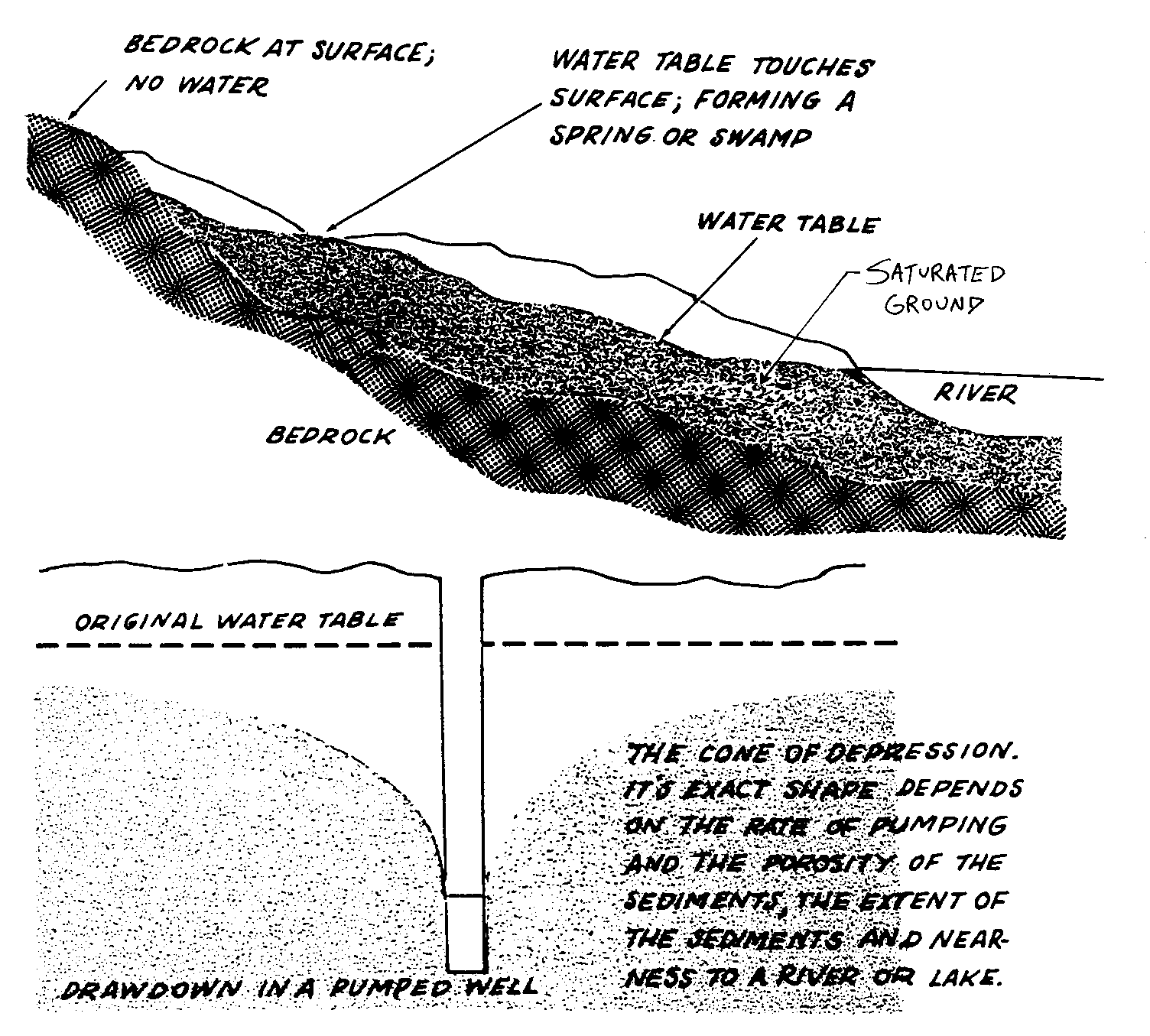
surface or deep below ground. During rainy weather the water
table may be higher than normal and during dry seasons it may be
lower.
How Wells Work
A water well is a hole that is dug, driven, or drilled through
the earth, into the aquifier, to remove ground water for human
use. The sides of the hole can be left without support, but are
often supported by brick, stone, concrete, steel pipe, or other
materials. Water is removed from the well by a variety of
methods, of which the simplest is lowering and raising a bucket
or other container. A variety of pumps can also be used; these
may be hand operated or powered by petrol, electricity, wind, or
other means.
Most hand-dug wells are less than 30 meters deep, but deeper
wells have been successfully constructed under special conditions
(Figure B). Machine-drilled wells have been drilled several
38p03.gif (600x600)
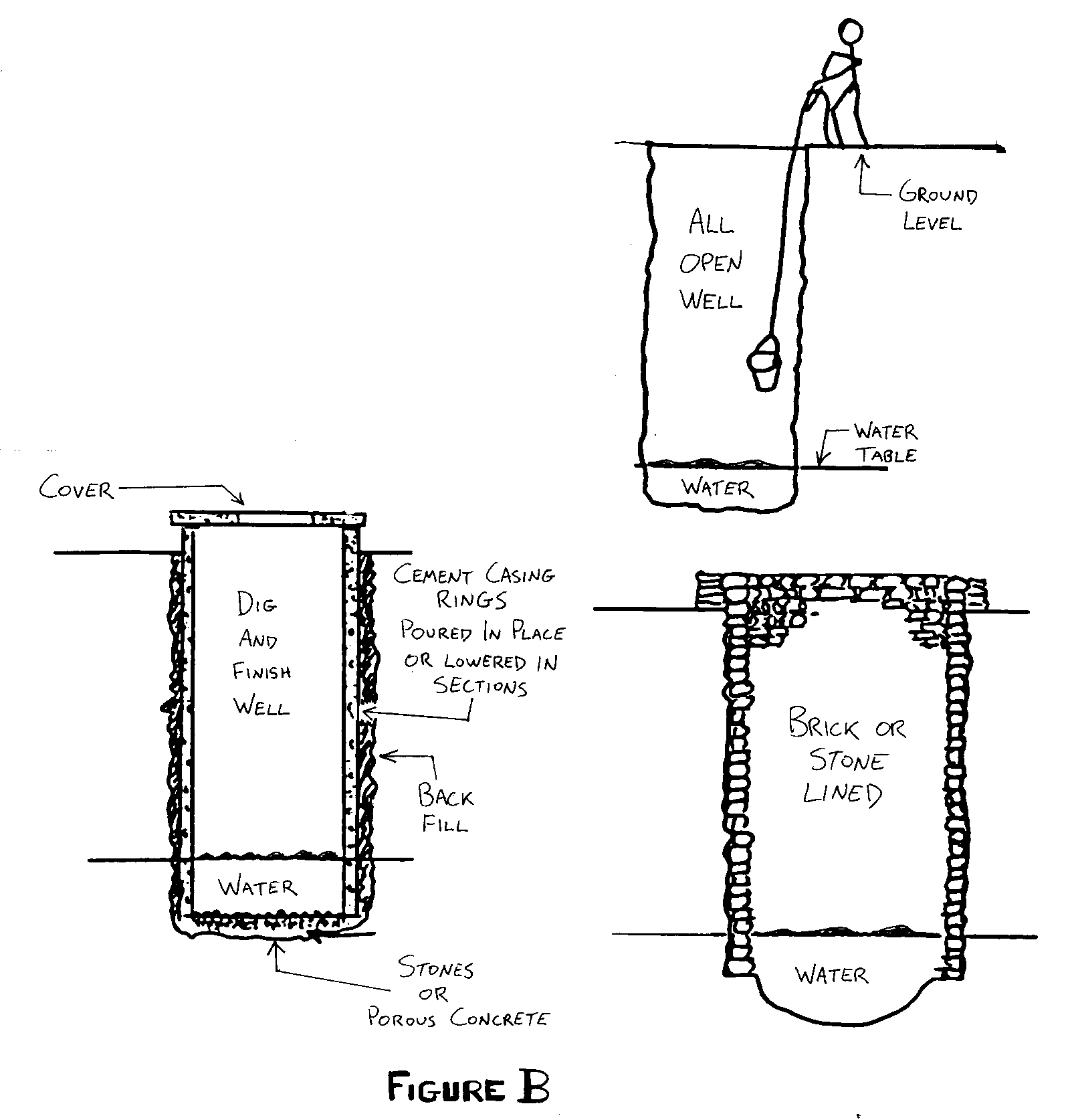
hundred meters deep.
When a hole, or well, is drilled or
dug into an aquifer, a pool develops
at the bottom of the hole. If undisturbed,
the well will fill to the
level if the water table. When the
well is finished and in use by drawing
water out, new water flows in to
refill the well; this process is
called recovery. The rate of recovery
depends on the coarseness of the soil
and the amount of gravel in the aquifer.
In sand and gravel aquifers,
recovery is very fast. In fine-grained
sand it is slower.
There are basically three sections to a well:
o The sanitary seal at the top,
o the well casing or well support in the middle, and
o the well intake or well screen at the bottom.
The top section must be finished so that it stands higher than
the ground and is sealed on the outside from surface water that
would otherwise drain into the well. Clay or concrete can be used
to seal the well for a distance of at least five meters away from
the casing. The middle section should be straight and well supported
with a strong wall or casing to keep the surrounding soil
from caving in.
The lowest, or water-bearing, section should extend as deeply
into the aquifer as possible.
The well screen or well intake of the
lowest section must allow the water to
flow into the well but not admit fine
soil particles (Figure C). For the
38p04.gif (600x600)
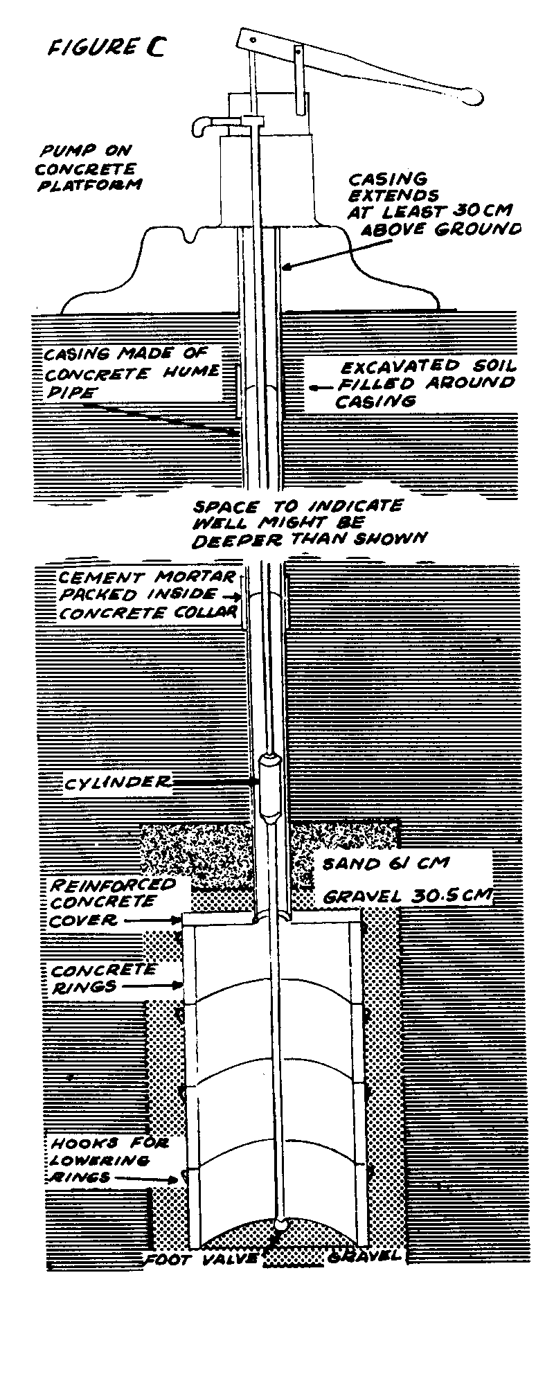
water to enter the well, it is important
that the well casing have many
small holes. If only the bottom of
the casing is open to the aquifer,
only a small amount of water can be
pumped. If the casing in the aquifer
has many small holes (slots in steel
or plastic pipe, or drilled holes in
concrete) more water will be available
to the well and the water is likely to
be cleaner. This is true because the
presence of many holes will lower the
entrance velocity of the water, which
thus will carry fewer particles.
Some wells are made without a casing.
In sandy soil, prefabricated concrete
rings, stones, or bricks can stabilize
the walls. But often a concrete well
casing must be made in place. Concrete
for well casings should be made from a
mixture of one part cement, two to
three parts sand, and four to five
parts gravel. To make the more porous
concrete for the water bearing portion
of the casing, use one part cement,
one part sand, and four parts gravel.
Mix in the normal way with about five
gallons of water per 50 kg bag of
cement.
WHERE AND WHEN TO DIG THE WELL
Avoid areas of poor water quality.
Checking local maps and the closest
water wells to the proposed new site
can give valuable information on the quality of water that can be
expected f rom the new well. Samples of water f rom existing wells
can be sent to a laboratory to determine the mineral and bacterial
content.
Contamination from surface sources must be avoided in selecting
the proposed well site. For example, avoid latrines, animal
stalls or barns, creeks, cemeteries, agricultural fields (pollution
from pesticides, herbicides, etc.), and roads (fuels and
coolants). The well should be constructed 50 to 100 meters from
the nearest potential source of surface contamination.
The water level in a well often changes from season to season and
from year to year. In dry seasons the water level will often be
low. wells that have penetrated the aquifer deeply are less
likely to go dry. For this reason it is best to dig the well
during the dry season. Some wells penetrate more than one aquifer
and are therefore more dependable for a permanent supply of
water. Moreover, water from deeper aquifers is less likely to
be contaminated.
HEALTH AND SAFETY DURING CONSTRUCTION
Health Measures
During well construction, precautions must be taken to clean any
tools that have been used in other projects because they may be a
source of contamination. The well should be covered after each
day's work to protect it from falling debris. Sanitary toilets
should be provided for the construction workers, who should be
warned against using the area near the well for this purpose.
Defecating or urinating in the well during or after construction
should be strictly prohibited.
Safety Measures
Many risks are associated with a hand dug well, especially if the
open type is decided upon. Understanding these risks and strictly
obeying simple safety procedures will minimize the chance of
an accident. The biggest risk is a massive cave-in that traps
the diggers. Other dangers arise from objects falling from the
surface on top of the diggers and misunderstood instructions from
the diggers below to the workers above. Without necessary vertical
supports and casing rings that stand above ground level, a
worker may accidentally fall into the well. The rope and pulley
assembly used to lower objects into the well can fail or the
bucket can be allowed to descend too rapidly. Heavy tools may
cause blows to the foot or hand.
Conditions inside a well are often hot and humid, and hard labor
under these conditions can cause fatigue and fainting. Fresh air
sometimes becomes displaced by other gases or it may become very
scarce. Petrol-engine exhaust and natural explosive gases from
within the earth are particularly deadly. Hence, a ventilation
system is a must when working below 10 meters. Pipes or hoses to
carry fresh air from the surface to the diggers must be used. A
hand operated fan or bellows can be the responsibility of one
person at the surface who ensures that the ventilation system is
operating continuously while the diggers are working in a well
deeper than 10 meters.
A further hazard arises when continuing to remove the soil after
the water table is reached. To dig the well deeper, the water
must be removed as it flows in from the surrounding aquifer,
either by pumping or with buckets. The inflow carries soil with
it, thus undermining the part of the well hole below the water
table. Eventually, as the soil is brought out with the water that
is removed, a doughnut-shaped cavern will form around the well
hole. This greatly increases the danger of cave-in.
To minimize the danger, build a caisson
having the same diameter as the
well hole and lower it to the bottom
(Figure D). It can be made of 200-liter
38p06.gif (600x600)
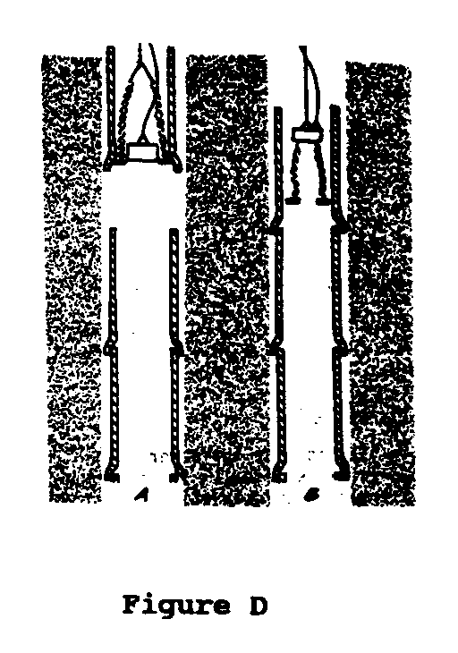
oil drums by cutting down one
side and splicing together as many as
are needed to reach the needed diameter.
If metal drums are not available,
wood or bamboo slats overlaid with
plastic sheet will do. In this way,
the migration of silt and sand into
the hole will be prevented or greatly
reduced, while the water is being
removed to permit further digging. The
caisson should be loose enough to
settle down as the hole is deepened.
If necessary, a second caisson can be
built and placed on top of the first
one.
V. WELL-DIGGING METHODS
Whether hand or machine methods are used, digging is easiest in
areas of loam, sand, or gravel and where small stones are present
(Table 1). Digging a well is very difficult in highly compacted
soils, fissured (cracked) rock, and rocky terrain. It is important
to select the equipment most appropriate for the soil type
and terrain.
TABLE I
TYPES OF WELLS AND SOIL CONDITIONS
GENERAL GUIDE OF SIZES AND CONDITIONS
FOR EACH TYPE OF DRILLING SYSTEM
MACHINE DRILLED
HAND HAND PERCUSSIONAUGERROTARYAIR
DUGDRILLED HAMMER
Diameters
1-20m 10-20cm 15-50cm 15-50m 15-50m 15-50m
Depths
2-40m 10-50m 20-500m 20-500m 20-500m 20-500m
SOIL TYPES
FOR DRILLING
Top Soil yes yes yes yes yes yes
Sandy loam yes yes yes yes yes yes
Clay yes yes yes yes yes yes
Silt yes yes yes yes yes yes
Sand yes yes yes yes yes yes
Sand stone slow no yes no yes yes
Lime stone yes no yes no yes yes
Gravel yes yes yes yes yes yes
Cobble stones yes no no no no no
Boulders ? no no no no yes
Dense rock no no no no no yes
Hand-Dug Wells
Unsupported wells. Open wells typically have diameters of 1 to 3
meters though wells larger than 4 meters in diameter are sometimes
dug. The wells may be 10 meters deep or less, without a
supporting wall and surface supports or frame.
Supported wells. Hand-dug wells are generally built by one of two
methods. In the first method, temporary forms are used to prevent
the walls of the well from caving in as digging goes on. After
digging is completed, the temporary forms are removed and the
wall is then reinforced with steel, plastic, bricks, rocks or
cement casing. (Wood or nondurable materials should be used only
for the temporary forms and not for permanent well casing). This
method is faster and less expensive than the second type, but is
more likely to cave in. It is appropriate if the well is relatively
shallow and large in diameter and the soil is very compact.
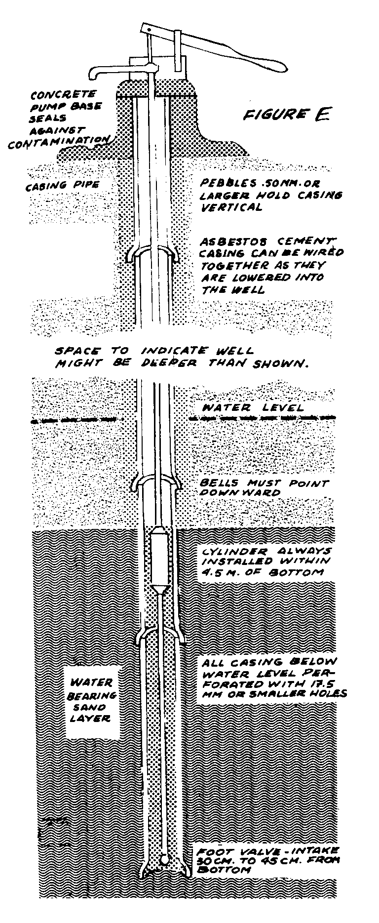
The second type of hand-dug well is constructed by reinforcing
the vertical walls as the well is dug so that when the water
table is reached, the reinforcement casing materials of the first
and second sections are already in place. The last portion of
the well to be completed (the water-bearing section) is dug and
cased as deeply into the aquifer as possible. Deep penetration
of the aquifer can be achieved if water is pumped from the well
during construction (Figure E).
38p08.gif (600x600)
Concrete-Cased Wells
Wells can also be classified according
to the methods for making and installing
the concrete casing sections.
"Dig and Finish" wells vary in diameter
from one to three meters. They are
constructed by completely digging the
first section followed by digging the
second section a meter at a time. At
each meter of depth cement is poured
to finish the casing before digging is
resumed. This sequence is repeated
until the aquifer in reached. The
water-bearing section of the well is
then completed by lowering surface-constructed
casing sections to the
bottom and allowing then to sink into
the aquifer.
"Dig Complete and Finish Complete" is
a method used with wells that are
usually no deeper than 20 meters. The
soil must be firm and temporarily
supported to reduce the risk of cave-in. This kind of well is dug
without interruption until the aquifer is reached and then is
finished by lowering the casing (made at the surface) into the
well from the top.
A third method is "Pour and Form." In this method forms made of
metal or strong plywood are placed at the bottom of the completed
well. Concrete is poured, and the forms are moved up about a
meter at a time until the well casing is complete. Another type
of form is used at the surface, where its casing can be constructed
without the restricted working conditions within the
well. After the casing has cured, the forms are removed. Reinforcement
rods are installed and locating rings can be formed
easily by the molds. A major disadvantage of this and the
Dig-and-Finish types is the need for a heavy framework with a
strong rope and pulley assembly to safely lower the heavy concrete
casing into the well.
Hand-Drilled Wells
To drill a well 5 to 20 meters deep in soft soils, an auger is
rotated at the surface by one or several workers using handles
attached to it. The auger should be withdrawn from the hole at
every meter or so and cleaned at the surface. When drilling is
completed, a plastic or steel casing should be lowered to the
bottom. Usually, hand pumps are then installed at the surface.
A percussion device can be used to drill a well 20 to 60 meters
deep through more compact soils. A tripod or framework is supported
vertically with a rope and pulley (Figure F).
38p10a.gif (600x600)
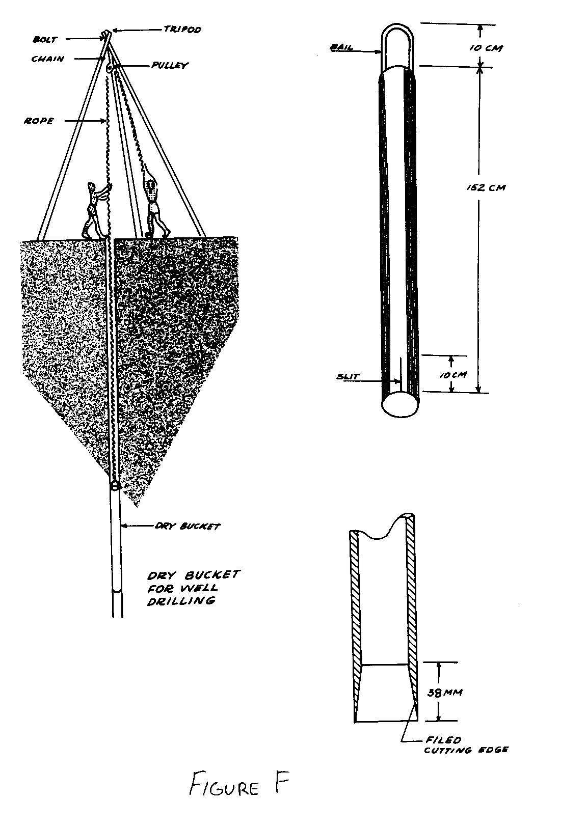
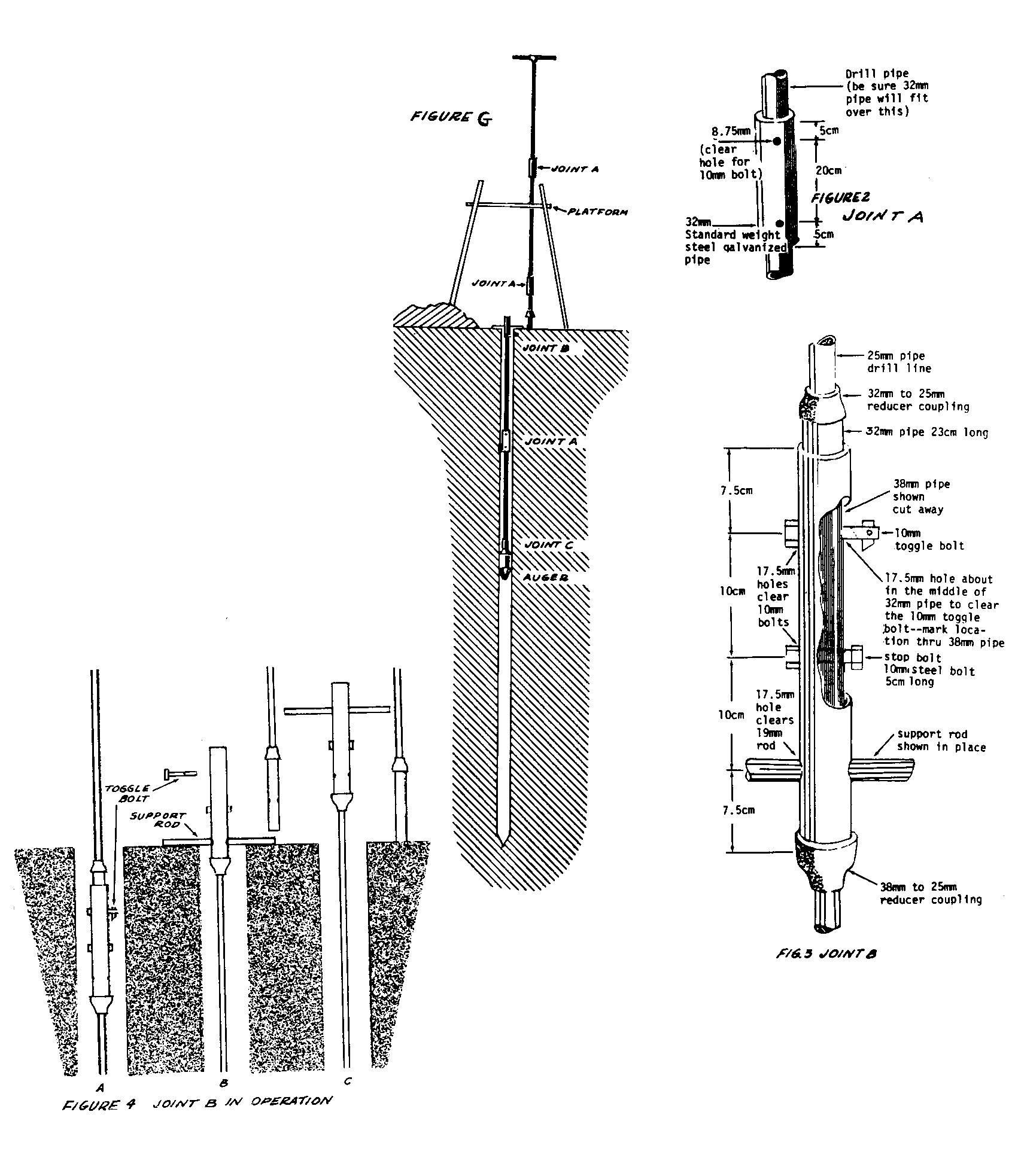
The rope is attached to the drilling tool and in a bouncing
motion should be repeatedly pulled and dropped. This will penetrate
the earth deeper and deeper as the weight of drilling tool
causes loosening of the soils. Sometimes tools are constructed to
trap the earth inside, much like an auger, and are brought to the
surface and cleaned each step of the way (Figure G). Other tools
38p10b.gif (600x600)
are designed to loosen the soils, with a long narrow bailing
bucket to lower into the well. Water is poured into the well to
form mud. The soil can then be removed with the bucket.
Machine-Drilled Wells
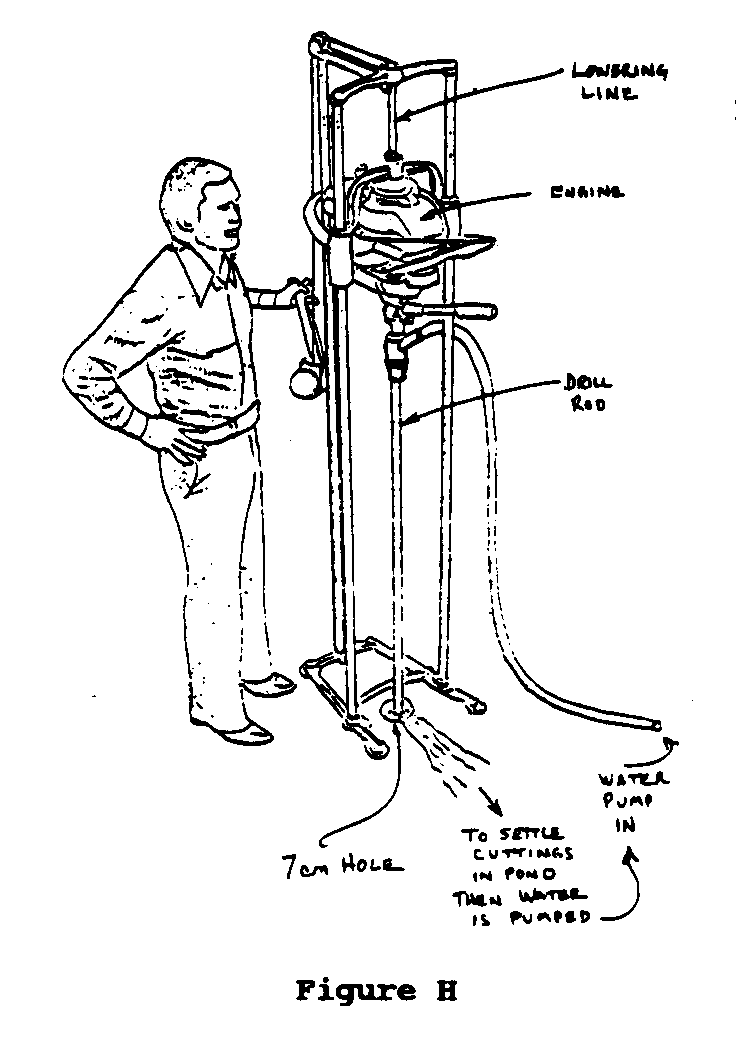
Small Machines. Small well drilling machines with engines are
available to bore a hole in the earth. These machines are efficient,
of moderate cost, and require only a few days to sink a
well. Water is pumped down through the center of the drill pipe
to lubricate the bit in the bottom of the well. As the drill rotates,
it cuts the soil, which is flushed back to the surface
with the returning water. The water-mid slurry is then be pumped
back down the drill stem. When the drill pipe penetrates all of
the aquifer, the well is completed as described below (Figure H).
38p11a.gif (600x600)
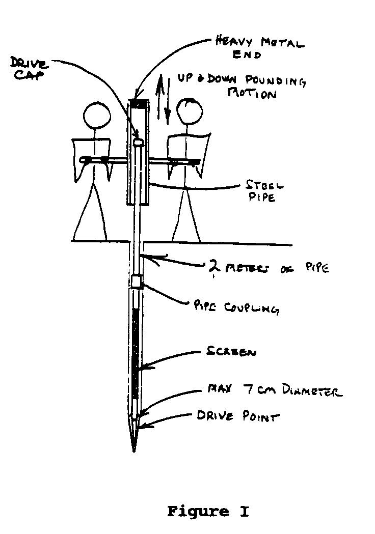
Wells can also be driven into the earth with drive points using
specially designed hammers or tripod driving tools (Figure I).
38p11b.gif (600x600)
Large machines. Larger wells (10 to 50 cm in diameter) can be
drilled quite efficiently with a truck-mounted machines quite
efficiently using an auger, or a percussion, rotary, or air hammer.
Steel or plastic casings are lowered when the drilling is
complete.
Several kinds of earth augers (Figure J) are used in well drilling.
38p12.gif (600x600)
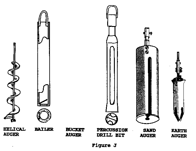
Each is suitable for a particular soil condition. Another
method involves using an engine driven pump and water power to
"jet" the well into the earth. In this method, water is forced
down an inner pipe and through a cutting bit. The water returns
to the surface through a larger pipe. Both pipes are moved back
and forth to allow the cutting edge at the bottom to force the
drilled and loosened soil to come up to the surf ace with the
pumped water to the surface. The pipes slowly sink into the
ground. The success of this method depends on soil conditions.
Rocks or pebbles usually stop the process.
VI. WELL PUMPS
Suction and Down-Hole Pumps
An important decision is whether the water can be pumped by
suction or whether a "down-hole" pump must be used. Suction pumps
can be used in shallow" wells--those where the water tables less
than 8 meters below the surface. A well with a water lifting
requirement greater than 8 meters is considered a "deep" well
(Figure K). Atmospheric pressure can force water up pipes to a
38p13.gif (600x600)
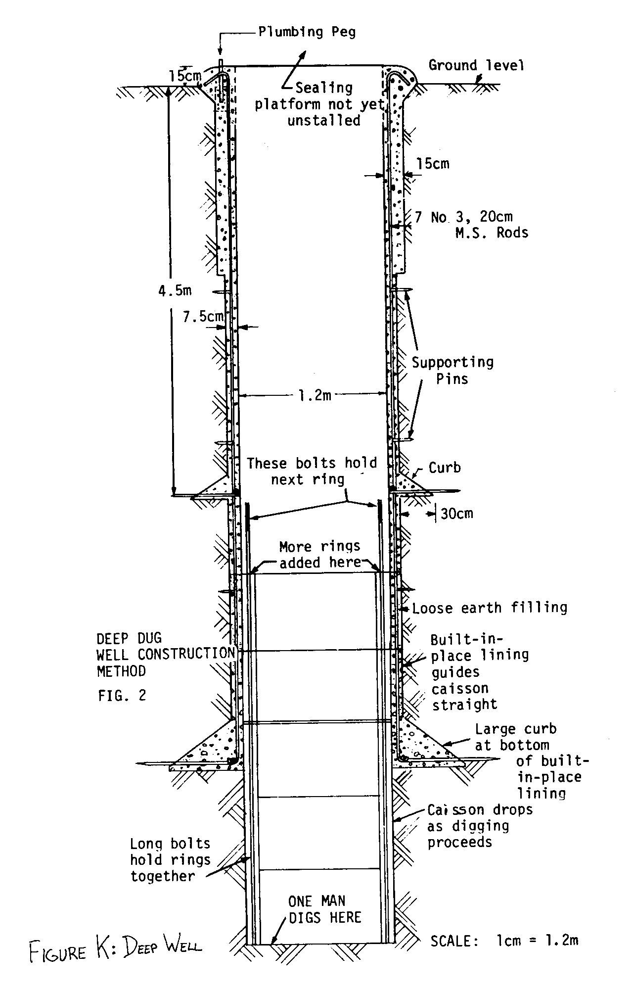
theoretical maximum of 10 meters. At greater depths, operation
of a suction pump is not possible. Down-hole pumps can be used
at any depth.
The machinery or "action" (including the piston, diaphragm, and
so on) of a suction pump is at the surface. The action of down-hole
pumps is below the water table.
Positive-Displacement and Centrifugal Pumps
The two commonly used types of waterwell pumps for the wells
described here are positive displacement (or piston) and centrifugal.
Each has its limitations and advantages.
Centrifugal pumps run at higher speeds
than can be obtained with hand operation.
They are usually powered by
petrol or diesel engines, or by electric
motors. Positive displacement
pumps are used for hand-pumped wells.
Their cylinders can be mounted at the
surface and the water can be dispensed
from the well through a single pipe.
In deep wells, the cylinders can be
installed at the bottom of the well,
from where they push the water to the
surface. They can be hand driven,
powered by a submersible motor at the
bottom, or driven by a shaft linked to
an electric motor at the surface.
Singlestage centrifugal pumps can be
used at the surface to draw the water
from shallow wells, but in deep wells,
several stages of centrifugal pumping
may be needed.
A jet pump (Figure L) is another type
38p14a.gif (600x600)
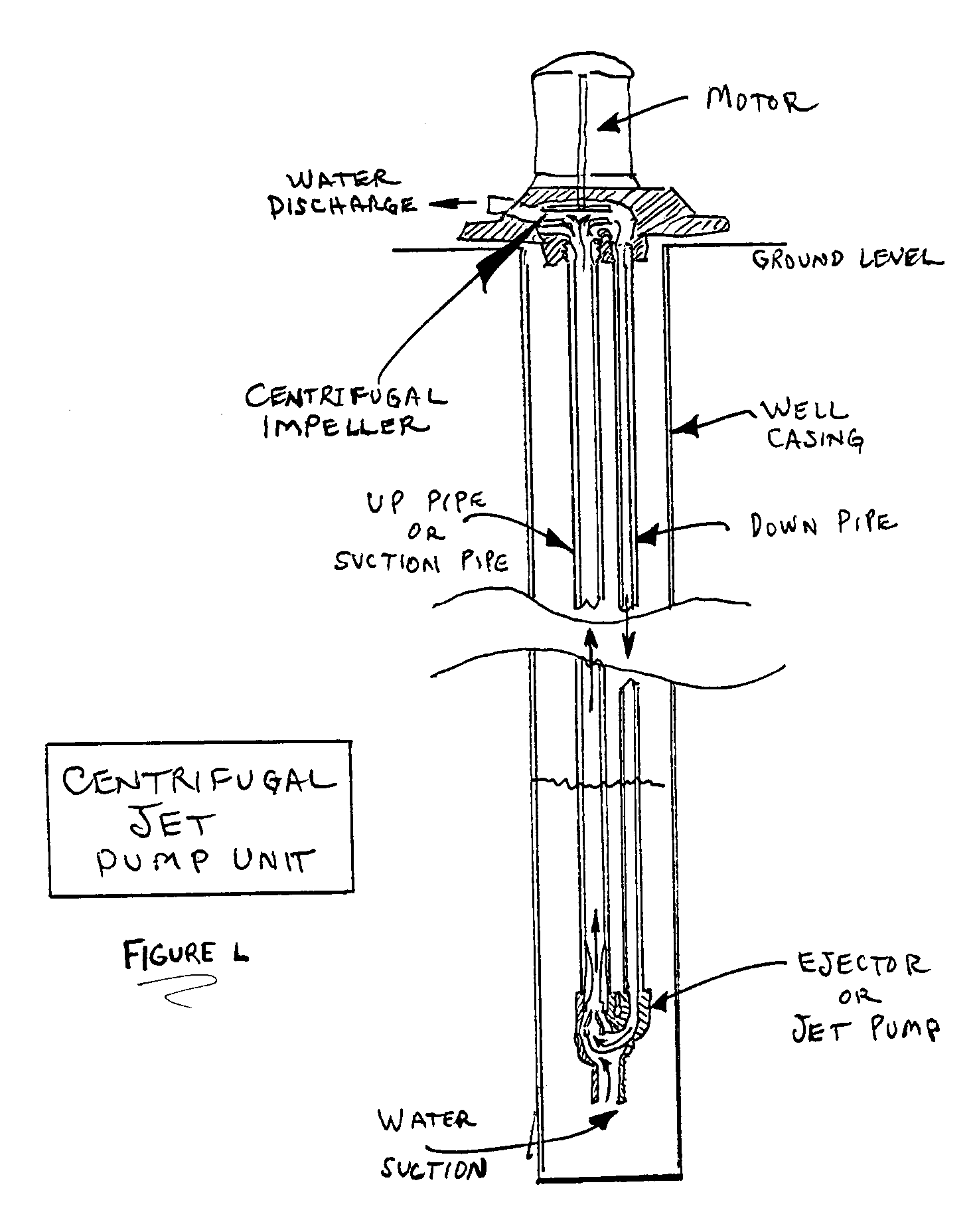
of centrifugal pump used at the surface
for pumping water from deep
wells. It circulates water down one
pipe through a high-pressure nozzle
and returns it to the surface through
a second pipe when a small portion is
drawn off for use. This system is
efficient only at depths less than 15
meters.
Power for Pumps
If hand pumps are not used, windmills may be a good choice for
lifting water from shallow or deep water wells in rural communities,
where conventional power supplies or fuel costs are very
expensive (Figure M). The initial cost of windmills is high, but
38p14b.gif (600x600)
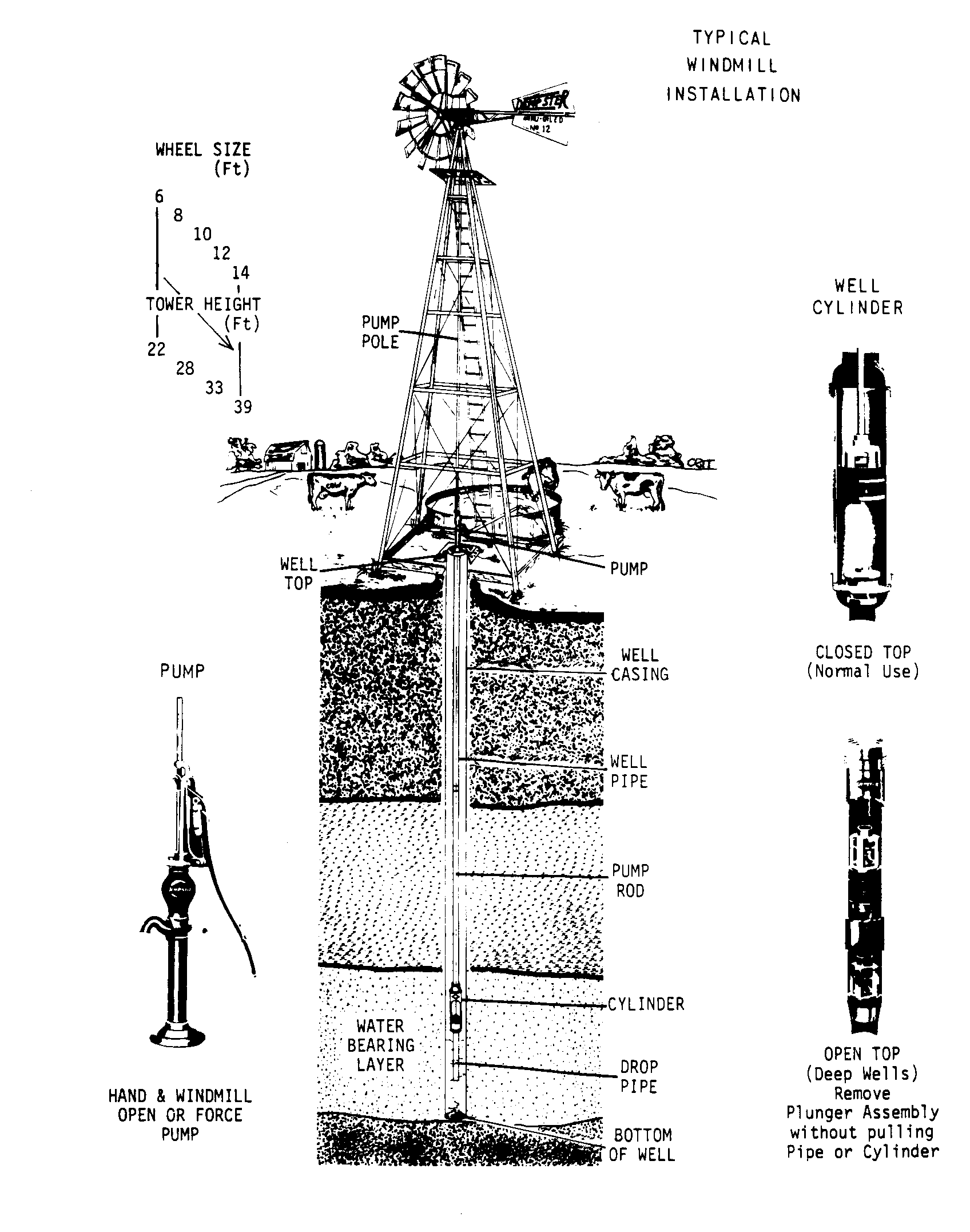
they are dependable machines and last many years. When a single
well is to be used as a community project, a windmill can be an
excellent investment.
Modern technology has produced solar cells that convert sunlight
directly into electricity. one of the most important applications
for solar cells, in rural areas all over the world, is water
pumping. Large companies are competing to produce solar cells
cheaply, at a cost affordable in the United States and developing
nations.
VII. CARE OF THE WELL AFTER COMPLETION
Water in untapped aquifers is sealed from microorganisms and is
therefore uncontaminated. Once well digging begins, the aquifer
is exposed to then and other particles in the air. For this
reason, after the well has been constructed, the water in it must
be returned to a safe condition.
First, the completed well should be thoroughly disinfected with
chlorine before anyone drinks the water. Ordinary liquid household
bleach (containing 5.2 percent chlorine) is commonly used.
The procedure is as follows: (1) Mix two liters of chlorine
bleach into 40 liters of clean water (see Table 2). (2) Pour it
into the well. If a hand pump has been installed at the surface,
pump the water through it and directly back into the well for a
few minutes. (3) Allow the well to stand idle overnight: or at
least eight hours. (4) Pump the treated water from the well until
no chemical odor is noticeable.
Verify your procedure with a local doctor or health care worker
in advance. If possible, a sample of water from the well (after
disinfection) should be sent to a laboratory to test its safety
as drinking water.
TABLE II
AMOUNTS OF CHEMICALS REQUIRED FOR A
STRONG CHLORINE SOLUTION CAPABLE OF
DISINFECTING WELLS AFTER THEIR CONSTRUCTION(*)
Water Bleaching Powder High Strength Liquid Bleach
([m.sup.3]) (25-354) (g) Calcium Hypochlorite (5% Sodium
(70%) (g) Hypochlorite) (ml)
0.1 10 4.3 60
0.12 12 5.2 72
0.15 15 6.5 90
0.2 20 8.6 120
0.25 25 11 150
0.3 30 13 180
0.4 40 17 240
0.5 50 22 300
0.6 60 26 360
0.7 70 30 420
0.8 80 34 480
1 100 43 600
1.2 120 52 720
1.5 150 65 900
2 200 86 1 200
2.5 250 110 1 500
3 300 130 1 800
4 400 170 2 400
5 500 220 3 000
6 600 260 3 600
7 700 300 4 200
8 800 340 4 800
10 1 000 430 6 000
12 1 200 520 7 200
15 1 500 650 9 000
20 2 000 860 12 000
30 3 000 1 300 18 000
40 4 000 1 700 24 000
50 5 000 2 200 30 000
60 6 000 2 600
70 7 000 3 000
80 8 000 3 400
100 10 000 4 300
120 12 000 5 200
150 15 000 6 500
200 20 000 8 600
250 25 000 11 000
300 30 000 13 000
400 40 000 17 000
500 50 000 22 000
(*) This produces a chlorine concentration of approximately 30 mg/l
(ppm). This water should not be drunk by people or animals.
The community should be informed on how to keep the water safe to
drink. Users should be trained in simple health procedures and
general rules for proper water use. Boiling or chlorinating
(Table 3) the water at home is often needed, in addition to basic
well sanitation. Washing or cooking should not be permitted in
the immediate area of the well. Animals should be restricted from
the immediate area of the well and kept at a safe distance. Only
repair and maintenance workers should enter the well. Before the
well is put back into service after a repair, it should be
disinfected using the same method as when the well was first put
into service. No pools or stagnant water should be allowed to
collect around the well surface. These pools can be breeding
areas for insects as well as for microorganisms, and can spread
diseases that can be acquired by simply walking through them.
No bucket or ropes with surface dirt should be allowed to enter
the well. Ropes and buckets used to draw water from the well can
transfer contamination from hands to rope and then to the well
water. In this way, any person later drawing water from the well
can take home enough microorganisms to make the family ill when
they drink it.
VII. MANAGEMENT CONSIDERATIONS
The need for a safe drinking water supply as expressed by the
people of the community should be analyzed by workers who are
responsible for deciding whether to construct the well. Successful
projects require good leadership, planning, and execution,
but community initiative, planning, ownership, and support are
essential from the start to ensure that the well is built where
users want it, that the users understand how it will be paid for,
that the well does not adversely affect the social structure of
the community, that it is used, that the well and pump are maintained,
and that water is clean when drawn and kept under sanitary
conditions by its users.
The first consideration should be for good water quality. Other
considerations include cost and maintenance of the system. What
is the total amount of money needed? Where will the construction
money come from? Who will be responsible for repairing and
maintaining the well and the pump through the years? If the
project is for several wells in a community, a number of issues
must be carefully resolved to arrive at the proper decision. For
example:
o the local requirements for water
o the kind of wells
o the workers and their pay
o the type of equipment to use
o the costs and materials required for construction
o the availability of the materials
TABLE III
AMOUNTS OF CHEMICALS NEEDED TO
DISINFECT A KNOWN QUANTITY OF
WATER FOR DRINKING(*)
Water Bleaching Powder High Strength Liquid Bleach
([m.sup.3]) (25-35%) (g) Calcium Hypochlorite (5% Sodium
(70%) (g) Hypochlorite) (ml)
1 2.3 1 14
1.2 3 1.2 17
1.5 3.5 1.5 21
2 5 2 28
2.5 6 2.5 35
3 7 3 42
4 9 4 56
5 12 5 70
6 14 6 84
7 16 7 98
8 19 8 110
10 23 10 140
12 28 12 170
15 35 15 210
20 50 20 280
30 70 30 420
40 90 40 560
50 120 50 700
60 140 60 840
70 160 70 980
80 190 80 1 100
100 230 100 1 400
120 280 120 1 700
150 350 150 2 100
200 470 200 2 800
250 580 250 3 500
300 700 300 4 200
400 940 400 5 600
500 1 170 500 7 000
(*) Approximate dose = 0.7 mg of applied chlorine per litre of water.
o permits and advance approvals by local authorities
o financing of continued operation/repairs/maintenance
The local availability of construction materials and water lifting
devices should be a major factor in the selection of the type
of well to be considered (Table 4). Imported items will raise
the cost considerably. Sometimes hand pumps or machine operated
pumps will be part of the project. Their selection and maintenance
will require people with more advanced skills.
Local authorities must be consulted on laws and regulations that
will apply to the new well project. Someone must be assigned to
keep records so that details of the project can be reviewed. The
records can often be used to resolve disputes or misunderstandings.
TABLE IV
ADVANTAGES AND DISADVANTAGES
OF VARIOUS TYPES OF WELLS AND PUMPS
WELL TYPE ADVANTAGES DISAVTAGES
Hand Inexpensive Unable to dig deep into
Dug water-bearing areas
Easy to do Dangerous to construct
Easy to maintain Contaminates easily
Machine Gets deep in Cost more to drill
Dug Water-bearing areas
Safety in drilling Site must be accessible
Easy to seal Needs expensive casing
Good for hand pumps Requires skilled people
Usually safer water
Cylinder Slow speed Small volumes pumped
Pumps
Low Cost
Easily repaired
Locally available
Simple equipment to
install
Centrifugal Efficient High cost
Pumps
Quiet operation Usually an import item
More costly to maintain
More skilled to repair
Needs high speed driver
Large equipment to install
Not adaptable to windmills
BIBLIOGRAPHY
Brush, Richard E. "Wells Construction." Peace Corps Information
Collection Exchange, 806 Connecticut Avenue NW, Washington, D.C.
20525. Action Pamphlet 4200.35, 1979.
Davis, S.N. and DeWiest, R.J.M.Hydrogeology. John Wiley and
Sons, New York, New York, 1966.
DHV Consulting Engineers.Shallow Wells.P.O. Box 85,
Amerfsoort, The Netherlands, 1979
Driscoll, F.G. Groundwater and Wells, ed.2, Johnson Division,
St. Paul, Minnesota, 1986.
Gibson, Ulric P. and Singer, Rexford D. Small Wells Manual.
Agency for International Development, Washington, DC 20523 USA,
1969.
Koegel, R.G. Self-Help Wells.Food and Agriculture Organization
of the United Nations, Rome, Italy, 1977.
Peace Corps Volunteers.Construction and Maintenance of Water
Wells. Volunteers for International Technical Assistance Inc.,
Schenectady, New York, 1969.
Village Technology Handbook.Volunteers in Technical Assistance,
1815 North Lynn Street, Suite 200, Arlington, Virginia 22209-8438
USA. 1988.
Watt, S.B. and Wood, W.E. Hand Dug Wells and Their Construction.
Intermediate Technology Publications, London, England, 1979.
GLOSSARY
Apron - A slightly sloped concrete pad that surrounds the well
and helps prevent contaminated surface water from finding its way
back into the well.
Aquifier - A water-bearing layer (stratum) of permeable rock,
sand, or gravel.
Bit - The cutting piece at the bottom end of the tool string that
loosens the soil or rock to deepen the hole.
Bottom Section - That part of-the well that extends beneath the
water table.
Casing - The vertical support inside the well. Cement cylinders,
plastic, or steel pipe. Sometimes called caissons, lining.
Curb - A part of the well lining that extends out from the place
and prevents it from sliding down.
Cutting Ring - A sharp-edged ring used on the bottom of a lining
that is being sunk into place to make sinking easier.
Drop Pipe - That section of pipe in a deep well pump assembly
that extends between the pump cylinder from flowing back into
the well.
Foot Valve - A valve at the bottom of the suction pipe that prevents
the water pulled up into it by the cylinder from flowing
back into the well.
Ground Water - Water contained in the part of the gorund that is
completely saturated. Ground water accumulates in quantity in
aquifiers, from which it can be drawn out of the ground through
wells.
Hydrologic Cycle - Continual natural cycle through which water
moves from oceans to clouds to ground and ultimately back to the
oceans.
Intake Section - That part of the bottom section through which
water enters the well.
Level (adjective) - Perfectly horizontal.
Level (noun) - A device used to establish a perfectly horizontal
line.
Middle Section - That part of the well between the ground surface
and the water table.
========================================
========================================
UNDERSTANDING
WATER WELLS
By William Ashe
Technical Reviewers
Douglas Denatale
Joseph Gitta
William Lorah
Robert Moran
P. Alen Pashkevich
Don Wells
Published By
VITA
1600 Wilson Boulevard, Suite 500
Arlington, Virginia 22209 USA
Tel: 703/276-1800 * Fax: 703243-1865
Internet: pr-info@vita.org
Understanding Water Wells
ISBN: 086619-307-3
[C] 1990, Volunteers in Technical Assistance
PREFACE
This paper is one of a series published by Volunteers in Technical
Assistance to provide an introduction to specific state-of-the-art
technologies of intrest to people in developing countries.
The papers are intended to be used as guidelines to help
people chooe technologies that are suitable to their situations.
They are not intended to provide construction or implementation
details. People are urged to contact VITA or a similar organization
for further information and technical assistance if they
find that a particular technology seems to meet their needs.
The papers in the series were written, reviewed, and illustrated
almost entirely by VITA Volunteer technical experts on a purely
voluntary basis. Some 500 volunteers were involved in the production
of the first 100 titles issued, contributing approximately
5,000 hours of their time. VITA staff included Patrice Matthews
handling typesetting and layout, and Margaret Crouch as project
manager.
The author of the paper William Ashe, is the Director of Lifewater
International. Mr. Ashe has experience in drip irrigation,
wind mills and jet pumps. He has travelled in Haiti, Dominican
Republic and Kenya.
The six reviewers who are all VITA Volunteers were, Douglas
Denatale who is employed by Whitman & Howard, Inc. and is experienced
in geology, Joseph Gitta, self-employed in Beekeeping,
William Lorah, a civil engineer with Wright Water Engineers,
Robert Moran, a consultant in geology, P. Alan Pashkevich an
engineer in Georgia Tech Research Institute, and Don C. Wells,
an engineer for the city of Portland.
VITA is a private, nonprofit organization that supports people
working on technical problems in developing countries. VITA
offers information and assistance aimed at helping individuals
and groups to select and implement technologies appropriate to
their situations. VITA maintains an international Inquiry Service,
a specialized documentation center, and a computerized
roster of volunteer technical consultants; manages long-term
field projects; and published a variety of technical manuals and
papers.
UNDERSTANDING WATER WELLS
By
VITA Volunteer William A. Ashe
BACKGROUND
Safe drinking water is a basic human need. Yet, according to the
World Bank, water-borne diseases are the leading cause of infant
mortality worldwide. These diseases are among the most serious
found in the developing world. There is no single community
project for development of long-term social and economic well-being,
health, and comfort of a small community that is more
important than a safe drinking-water supply.
Wells provide access to ground water, which is almost always
safer and cleaner than surface water from lakes and rivers.
Digging a well appears simple, and inexperienced and unskilled
people have made wells of many types, shapes, and sizes, with a
variety of tools. Such wells are usually not the best and often
prove dangerous during construction or after continued use. Those
used to supply drinking water for humans are often improperly
sealed at the surface and thus allow contaminated surface water
to drain back into the well. Contaminated water makes people
sick. Since the microorganisms (bacteria and viruses) that cause
the diseases are too small to be seen, some people find it hard
to believe that they are present. They often do not trace the
source of their sickness to contaminated water.
This paper tells how to dig a well that provides safe drinking
water for human consumption. Wells for animals and irrigation
can be constructed to a much lower standard.
The paper intends to help people decide what type of well is best
for them and whether hand-dug wells or drilled wells are within
their means. Drilled wells can be deeper, safer, and more durable
than hand-dug wells but their construction is more expensive and
in many rural areas, the equipment or funds for drilling may not
be available. Fortunately, simple machinery has been developed
that can be used if money or expertise is not too scarce. Although
this brings drilled wells within reach of some communities,
they remain too costly for others. In these cases, hand-dug
wells provide an alternative for producing safe drinking water.
Many good "how-to" books are available that describe in detail
the construction of different types of water wells. A few are
listed in the Bibliography.
PRINCIPLES
Ground Water
When it rains, some of the water soaks into the ground and is
trapped in porous soils. Other water flows into and through
layers of loose or porous rock. This is ground water. Water
saturated layers of rock and soil that can yield a supply of
water sufficient for wells or springs are called aquifers. The
level of the top of the saturated layers is called the water
table (Figure A). The water table may be fairly close to the
38p02.gif (600x600)
surface or deep below ground. During rainy weather the water
table may be higher than normal and during dry seasons it may be
lower.
How Wells Work
A water well is a hole that is dug, driven, or drilled through
the earth, into the aquifier, to remove ground water for human
use. The sides of the hole can be left without support, but are
often supported by brick, stone, concrete, steel pipe, or other
materials. Water is removed from the well by a variety of
methods, of which the simplest is lowering and raising a bucket
or other container. A variety of pumps can also be used; these
may be hand operated or powered by petrol, electricity, wind, or
other means.
Most hand-dug wells are less than 30 meters deep, but deeper
wells have been successfully constructed under special conditions
(Figure B). Machine-drilled wells have been drilled several
38p03.gif (600x600)
hundred meters deep.
When a hole, or well, is drilled or
dug into an aquifer, a pool develops
at the bottom of the hole. If undisturbed,
the well will fill to the
level if the water table. When the
well is finished and in use by drawing
water out, new water flows in to
refill the well; this process is
called recovery. The rate of recovery
depends on the coarseness of the soil
and the amount of gravel in the aquifer.
In sand and gravel aquifers,
recovery is very fast. In fine-grained
sand it is slower.
There are basically three sections to a well:
o The sanitary seal at the top,
o the well casing or well support in the middle, and
o the well intake or well screen at the bottom.
The top section must be finished so that it stands higher than
the ground and is sealed on the outside from surface water that
would otherwise drain into the well. Clay or concrete can be used
to seal the well for a distance of at least five meters away from
the casing. The middle section should be straight and well supported
with a strong wall or casing to keep the surrounding soil
from caving in.
The lowest, or water-bearing, section should extend as deeply
into the aquifer as possible.
The well screen or well intake of the
lowest section must allow the water to
flow into the well but not admit fine
soil particles (Figure C). For the
38p04.gif (600x600)
water to enter the well, it is important
that the well casing have many
small holes. If only the bottom of
the casing is open to the aquifer,
only a small amount of water can be
pumped. If the casing in the aquifer
has many small holes (slots in steel
or plastic pipe, or drilled holes in
concrete) more water will be available
to the well and the water is likely to
be cleaner. This is true because the
presence of many holes will lower the
entrance velocity of the water, which
thus will carry fewer particles.
Some wells are made without a casing.
In sandy soil, prefabricated concrete
rings, stones, or bricks can stabilize
the walls. But often a concrete well
casing must be made in place. Concrete
for well casings should be made from a
mixture of one part cement, two to
three parts sand, and four to five
parts gravel. To make the more porous
concrete for the water bearing portion
of the casing, use one part cement,
one part sand, and four parts gravel.
Mix in the normal way with about five
gallons of water per 50 kg bag of
cement.
WHERE AND WHEN TO DIG THE WELL
Avoid areas of poor water quality.
Checking local maps and the closest
water wells to the proposed new site
can give valuable information on the quality of water that can be
expected f rom the new well. Samples of water f rom existing wells
can be sent to a laboratory to determine the mineral and bacterial
content.
Contamination from surface sources must be avoided in selecting
the proposed well site. For example, avoid latrines, animal
stalls or barns, creeks, cemeteries, agricultural fields (pollution
from pesticides, herbicides, etc.), and roads (fuels and
coolants). The well should be constructed 50 to 100 meters from
the nearest potential source of surface contamination.
The water level in a well often changes from season to season and
from year to year. In dry seasons the water level will often be
low. wells that have penetrated the aquifer deeply are less
likely to go dry. For this reason it is best to dig the well
during the dry season. Some wells penetrate more than one aquifer
and are therefore more dependable for a permanent supply of
water. Moreover, water from deeper aquifers is less likely to
be contaminated.
HEALTH AND SAFETY DURING CONSTRUCTION
Health Measures
During well construction, precautions must be taken to clean any
tools that have been used in other projects because they may be a
source of contamination. The well should be covered after each
day's work to protect it from falling debris. Sanitary toilets
should be provided for the construction workers, who should be
warned against using the area near the well for this purpose.
Defecating or urinating in the well during or after construction
should be strictly prohibited.
Safety Measures
Many risks are associated with a hand dug well, especially if the
open type is decided upon. Understanding these risks and strictly
obeying simple safety procedures will minimize the chance of
an accident. The biggest risk is a massive cave-in that traps
the diggers. Other dangers arise from objects falling from the
surface on top of the diggers and misunderstood instructions from
the diggers below to the workers above. Without necessary vertical
supports and casing rings that stand above ground level, a
worker may accidentally fall into the well. The rope and pulley
assembly used to lower objects into the well can fail or the
bucket can be allowed to descend too rapidly. Heavy tools may
cause blows to the foot or hand.
Conditions inside a well are often hot and humid, and hard labor
under these conditions can cause fatigue and fainting. Fresh air
sometimes becomes displaced by other gases or it may become very
scarce. Petrol-engine exhaust and natural explosive gases from
within the earth are particularly deadly. Hence, a ventilation
system is a must when working below 10 meters. Pipes or hoses to
carry fresh air from the surface to the diggers must be used. A
hand operated fan or bellows can be the responsibility of one
person at the surface who ensures that the ventilation system is
operating continuously while the diggers are working in a well
deeper than 10 meters.
A further hazard arises when continuing to remove the soil after
the water table is reached. To dig the well deeper, the water
must be removed as it flows in from the surrounding aquifer,
either by pumping or with buckets. The inflow carries soil with
it, thus undermining the part of the well hole below the water
table. Eventually, as the soil is brought out with the water that
is removed, a doughnut-shaped cavern will form around the well
hole. This greatly increases the danger of cave-in.
To minimize the danger, build a caisson
having the same diameter as the
well hole and lower it to the bottom
(Figure D). It can be made of 200-liter
38p06.gif (600x600)
oil drums by cutting down one
side and splicing together as many as
are needed to reach the needed diameter.
If metal drums are not available,
wood or bamboo slats overlaid with
plastic sheet will do. In this way,
the migration of silt and sand into
the hole will be prevented or greatly
reduced, while the water is being
removed to permit further digging. The
caisson should be loose enough to
settle down as the hole is deepened.
If necessary, a second caisson can be
built and placed on top of the first
one.
V. WELL-DIGGING METHODS
Whether hand or machine methods are used, digging is easiest in
areas of loam, sand, or gravel and where small stones are present
(Table 1). Digging a well is very difficult in highly compacted
soils, fissured (cracked) rock, and rocky terrain. It is important
to select the equipment most appropriate for the soil type
and terrain.
TABLE I
TYPES OF WELLS AND SOIL CONDITIONS
GENERAL GUIDE OF SIZES AND CONDITIONS
FOR EACH TYPE OF DRILLING SYSTEM
MACHINE DRILLED
HAND HAND PERCUSSIONAUGERROTARYAIR
DUGDRILLED HAMMER
Diameters
1-20m 10-20cm 15-50cm 15-50m 15-50m 15-50m
Depths
2-40m 10-50m 20-500m 20-500m 20-500m 20-500m
SOIL TYPES
FOR DRILLING
Top Soil yes yes yes yes yes yes
Sandy loam yes yes yes yes yes yes
Clay yes yes yes yes yes yes
Silt yes yes yes yes yes yes
Sand yes yes yes yes yes yes
Sand stone slow no yes no yes yes
Lime stone yes no yes no yes yes
Gravel yes yes yes yes yes yes
Cobble stones yes no no no no no
Boulders ? no no no no yes
Dense rock no no no no no yes
Hand-Dug Wells
Unsupported wells. Open wells typically have diameters of 1 to 3
meters though wells larger than 4 meters in diameter are sometimes
dug. The wells may be 10 meters deep or less, without a
supporting wall and surface supports or frame.
Supported wells. Hand-dug wells are generally built by one of two
methods. In the first method, temporary forms are used to prevent
the walls of the well from caving in as digging goes on. After
digging is completed, the temporary forms are removed and the
wall is then reinforced with steel, plastic, bricks, rocks or
cement casing. (Wood or nondurable materials should be used only
for the temporary forms and not for permanent well casing). This
method is faster and less expensive than the second type, but is
more likely to cave in. It is appropriate if the well is relatively
shallow and large in diameter and the soil is very compact.
The second type of hand-dug well is constructed by reinforcing
the vertical walls as the well is dug so that when the water
table is reached, the reinforcement casing materials of the first
and second sections are already in place. The last portion of
the well to be completed (the water-bearing section) is dug and
cased as deeply into the aquifer as possible. Deep penetration
of the aquifer can be achieved if water is pumped from the well
during construction (Figure E).
38p08.gif (600x600)
Concrete-Cased Wells
Wells can also be classified according
to the methods for making and installing
the concrete casing sections.
"Dig and Finish" wells vary in diameter
from one to three meters. They are
constructed by completely digging the
first section followed by digging the
second section a meter at a time. At
each meter of depth cement is poured
to finish the casing before digging is
resumed. This sequence is repeated
until the aquifer in reached. The
water-bearing section of the well is
then completed by lowering surface-constructed
casing sections to the
bottom and allowing then to sink into
the aquifer.
"Dig Complete and Finish Complete" is
a method used with wells that are
usually no deeper than 20 meters. The
soil must be firm and temporarily
supported to reduce the risk of cave-in. This kind of well is dug
without interruption until the aquifer is reached and then is
finished by lowering the casing (made at the surface) into the
well from the top.
A third method is "Pour and Form." In this method forms made of
metal or strong plywood are placed at the bottom of the completed
well. Concrete is poured, and the forms are moved up about a
meter at a time until the well casing is complete. Another type
of form is used at the surface, where its casing can be constructed
without the restricted working conditions within the
well. After the casing has cured, the forms are removed. Reinforcement
rods are installed and locating rings can be formed
easily by the molds. A major disadvantage of this and the
Dig-and-Finish types is the need for a heavy framework with a
strong rope and pulley assembly to safely lower the heavy concrete
casing into the well.
Hand-Drilled Wells
To drill a well 5 to 20 meters deep in soft soils, an auger is
rotated at the surface by one or several workers using handles
attached to it. The auger should be withdrawn from the hole at
every meter or so and cleaned at the surface. When drilling is
completed, a plastic or steel casing should be lowered to the
bottom. Usually, hand pumps are then installed at the surface.
A percussion device can be used to drill a well 20 to 60 meters
deep through more compact soils. A tripod or framework is supported
vertically with a rope and pulley (Figure F).
38p10a.gif (600x600)
The rope is attached to the drilling tool and in a bouncing
motion should be repeatedly pulled and dropped. This will penetrate
the earth deeper and deeper as the weight of drilling tool
causes loosening of the soils. Sometimes tools are constructed to
trap the earth inside, much like an auger, and are brought to the
surface and cleaned each step of the way (Figure G). Other tools
38p10b.gif (600x600)
are designed to loosen the soils, with a long narrow bailing
bucket to lower into the well. Water is poured into the well to
form mud. The soil can then be removed with the bucket.
Machine-Drilled Wells
Small Machines. Small well drilling machines with engines are
available to bore a hole in the earth. These machines are efficient,
of moderate cost, and require only a few days to sink a
well. Water is pumped down through the center of the drill pipe
to lubricate the bit in the bottom of the well. As the drill rotates,
it cuts the soil, which is flushed back to the surface
with the returning water. The water-mid slurry is then be pumped
back down the drill stem. When the drill pipe penetrates all of
the aquifer, the well is completed as described below (Figure H).
38p11a.gif (600x600)
Wells can also be driven into the earth with drive points using
specially designed hammers or tripod driving tools (Figure I).
38p11b.gif (600x600)
Large machines. Larger wells (10 to 50 cm in diameter) can be
drilled quite efficiently with a truck-mounted machines quite
efficiently using an auger, or a percussion, rotary, or air hammer.
Steel or plastic casings are lowered when the drilling is
complete.
Several kinds of earth augers (Figure J) are used in well drilling.
38p12.gif (600x600)
Each is suitable for a particular soil condition. Another
method involves using an engine driven pump and water power to
"jet" the well into the earth. In this method, water is forced
down an inner pipe and through a cutting bit. The water returns
to the surface through a larger pipe. Both pipes are moved back
and forth to allow the cutting edge at the bottom to force the
drilled and loosened soil to come up to the surf ace with the
pumped water to the surface. The pipes slowly sink into the
ground. The success of this method depends on soil conditions.
Rocks or pebbles usually stop the process.
VI. WELL PUMPS
Suction and Down-Hole Pumps
An important decision is whether the water can be pumped by
suction or whether a "down-hole" pump must be used. Suction pumps
can be used in shallow" wells--those where the water tables less
than 8 meters below the surface. A well with a water lifting
requirement greater than 8 meters is considered a "deep" well
(Figure K). Atmospheric pressure can force water up pipes to a
38p13.gif (600x600)
theoretical maximum of 10 meters. At greater depths, operation
of a suction pump is not possible. Down-hole pumps can be used
at any depth.
The machinery or "action" (including the piston, diaphragm, and
so on) of a suction pump is at the surface. The action of down-hole
pumps is below the water table.
Positive-Displacement and Centrifugal Pumps
The two commonly used types of waterwell pumps for the wells
described here are positive displacement (or piston) and centrifugal.
Each has its limitations and advantages.
Centrifugal pumps run at higher speeds
than can be obtained with hand operation.
They are usually powered by
petrol or diesel engines, or by electric
motors. Positive displacement
pumps are used for hand-pumped wells.
Their cylinders can be mounted at the
surface and the water can be dispensed
from the well through a single pipe.
In deep wells, the cylinders can be
installed at the bottom of the well,
from where they push the water to the
surface. They can be hand driven,
powered by a submersible motor at the
bottom, or driven by a shaft linked to
an electric motor at the surface.
Singlestage centrifugal pumps can be
used at the surface to draw the water
from shallow wells, but in deep wells,
several stages of centrifugal pumping
may be needed.
A jet pump (Figure L) is another type
38p14a.gif (600x600)
of centrifugal pump used at the surface
for pumping water from deep
wells. It circulates water down one
pipe through a high-pressure nozzle
and returns it to the surface through
a second pipe when a small portion is
drawn off for use. This system is
efficient only at depths less than 15
meters.
Power for Pumps
If hand pumps are not used, windmills may be a good choice for
lifting water from shallow or deep water wells in rural communities,
where conventional power supplies or fuel costs are very
expensive (Figure M). The initial cost of windmills is high, but
38p14b.gif (600x600)
they are dependable machines and last many years. When a single
well is to be used as a community project, a windmill can be an
excellent investment.
Modern technology has produced solar cells that convert sunlight
directly into electricity. one of the most important applications
for solar cells, in rural areas all over the world, is water
pumping. Large companies are competing to produce solar cells
cheaply, at a cost affordable in the United States and developing
nations.
VII. CARE OF THE WELL AFTER COMPLETION
Water in untapped aquifers is sealed from microorganisms and is
therefore uncontaminated. Once well digging begins, the aquifer
is exposed to then and other particles in the air. For this
reason, after the well has been constructed, the water in it must
be returned to a safe condition.
First, the completed well should be thoroughly disinfected with
chlorine before anyone drinks the water. Ordinary liquid household
bleach (containing 5.2 percent chlorine) is commonly used.
The procedure is as follows: (1) Mix two liters of chlorine
bleach into 40 liters of clean water (see Table 2). (2) Pour it
into the well. If a hand pump has been installed at the surface,
pump the water through it and directly back into the well for a
few minutes. (3) Allow the well to stand idle overnight: or at
least eight hours. (4) Pump the treated water from the well until
no chemical odor is noticeable.
Verify your procedure with a local doctor or health care worker
in advance. If possible, a sample of water from the well (after
disinfection) should be sent to a laboratory to test its safety
as drinking water.
TABLE II
AMOUNTS OF CHEMICALS REQUIRED FOR A
STRONG CHLORINE SOLUTION CAPABLE OF
DISINFECTING WELLS AFTER THEIR CONSTRUCTION(*)
Water Bleaching Powder High Strength Liquid Bleach
([m.sup.3]) (25-354) (g) Calcium Hypochlorite (5% Sodium
(70%) (g) Hypochlorite) (ml)
0.1 10 4.3 60
0.12 12 5.2 72
0.15 15 6.5 90
0.2 20 8.6 120
0.25 25 11 150
0.3 30 13 180
0.4 40 17 240
0.5 50 22 300
0.6 60 26 360
0.7 70 30 420
0.8 80 34 480
1 100 43 600
1.2 120 52 720
1.5 150 65 900
2 200 86 1 200
2.5 250 110 1 500
3 300 130 1 800
4 400 170 2 400
5 500 220 3 000
6 600 260 3 600
7 700 300 4 200
8 800 340 4 800
10 1 000 430 6 000
12 1 200 520 7 200
15 1 500 650 9 000
20 2 000 860 12 000
30 3 000 1 300 18 000
40 4 000 1 700 24 000
50 5 000 2 200 30 000
60 6 000 2 600
70 7 000 3 000
80 8 000 3 400
100 10 000 4 300
120 12 000 5 200
150 15 000 6 500
200 20 000 8 600
250 25 000 11 000
300 30 000 13 000
400 40 000 17 000
500 50 000 22 000
(*) This produces a chlorine concentration of approximately 30 mg/l
(ppm). This water should not be drunk by people or animals.
The community should be informed on how to keep the water safe to
drink. Users should be trained in simple health procedures and
general rules for proper water use. Boiling or chlorinating
(Table 3) the water at home is often needed, in addition to basic
well sanitation. Washing or cooking should not be permitted in
the immediate area of the well. Animals should be restricted from
the immediate area of the well and kept at a safe distance. Only
repair and maintenance workers should enter the well. Before the
well is put back into service after a repair, it should be
disinfected using the same method as when the well was first put
into service. No pools or stagnant water should be allowed to
collect around the well surface. These pools can be breeding
areas for insects as well as for microorganisms, and can spread
diseases that can be acquired by simply walking through them.
No bucket or ropes with surface dirt should be allowed to enter
the well. Ropes and buckets used to draw water from the well can
transfer contamination from hands to rope and then to the well
water. In this way, any person later drawing water from the well
can take home enough microorganisms to make the family ill when
they drink it.
VII. MANAGEMENT CONSIDERATIONS
The need for a safe drinking water supply as expressed by the
people of the community should be analyzed by workers who are
responsible for deciding whether to construct the well. Successful
projects require good leadership, planning, and execution,
but community initiative, planning, ownership, and support are
essential from the start to ensure that the well is built where
users want it, that the users understand how it will be paid for,
that the well does not adversely affect the social structure of
the community, that it is used, that the well and pump are maintained,
and that water is clean when drawn and kept under sanitary
conditions by its users.
The first consideration should be for good water quality. Other
considerations include cost and maintenance of the system. What
is the total amount of money needed? Where will the construction
money come from? Who will be responsible for repairing and
maintaining the well and the pump through the years? If the
project is for several wells in a community, a number of issues
must be carefully resolved to arrive at the proper decision. For
example:
o the local requirements for water
o the kind of wells
o the workers and their pay
o the type of equipment to use
o the costs and materials required for construction
o the availability of the materials
TABLE III
AMOUNTS OF CHEMICALS NEEDED TO
DISINFECT A KNOWN QUANTITY OF
WATER FOR DRINKING(*)
Water Bleaching Powder High Strength Liquid Bleach
([m.sup.3]) (25-35%) (g) Calcium Hypochlorite (5% Sodium
(70%) (g) Hypochlorite) (ml)
1 2.3 1 14
1.2 3 1.2 17
1.5 3.5 1.5 21
2 5 2 28
2.5 6 2.5 35
3 7 3 42
4 9 4 56
5 12 5 70
6 14 6 84
7 16 7 98
8 19 8 110
10 23 10 140
12 28 12 170
15 35 15 210
20 50 20 280
30 70 30 420
40 90 40 560
50 120 50 700
60 140 60 840
70 160 70 980
80 190 80 1 100
100 230 100 1 400
120 280 120 1 700
150 350 150 2 100
200 470 200 2 800
250 580 250 3 500
300 700 300 4 200
400 940 400 5 600
500 1 170 500 7 000
(*) Approximate dose = 0.7 mg of applied chlorine per litre of water.
o permits and advance approvals by local authorities
o financing of continued operation/repairs/maintenance
The local availability of construction materials and water lifting
devices should be a major factor in the selection of the type
of well to be considered (Table 4). Imported items will raise
the cost considerably. Sometimes hand pumps or machine operated
pumps will be part of the project. Their selection and maintenance
will require people with more advanced skills.
Local authorities must be consulted on laws and regulations that
will apply to the new well project. Someone must be assigned to
keep records so that details of the project can be reviewed. The
records can often be used to resolve disputes or misunderstandings.
TABLE IV
ADVANTAGES AND DISADVANTAGES
OF VARIOUS TYPES OF WELLS AND PUMPS
WELL TYPE ADVANTAGES DISAVTAGES
Hand Inexpensive Unable to dig deep into
Dug water-bearing areas
Easy to do Dangerous to construct
Easy to maintain Contaminates easily
Machine Gets deep in Cost more to drill
Dug Water-bearing areas
Safety in drilling Site must be accessible
Easy to seal Needs expensive casing
Good for hand pumps Requires skilled people
Usually safer water
Cylinder Slow speed Small volumes pumped
Pumps
Low Cost
Easily repaired
Locally available
Simple equipment to
install
Centrifugal Efficient High cost
Pumps
Quiet operation Usually an import item
More costly to maintain
More skilled to repair
Needs high speed driver
Large equipment to install
Not adaptable to windmills
BIBLIOGRAPHY
Brush, Richard E. "Wells Construction." Peace Corps Information
Collection Exchange, 806 Connecticut Avenue NW, Washington, D.C.
20525. Action Pamphlet 4200.35, 1979.
Davis, S.N. and DeWiest, R.J.M.Hydrogeology. John Wiley and
Sons, New York, New York, 1966.
DHV Consulting Engineers.Shallow Wells.P.O. Box 85,
Amerfsoort, The Netherlands, 1979
Driscoll, F.G. Groundwater and Wells, ed.2, Johnson Division,
St. Paul, Minnesota, 1986.
Gibson, Ulric P. and Singer, Rexford D. Small Wells Manual.
Agency for International Development, Washington, DC 20523 USA,
1969.
Koegel, R.G. Self-Help Wells.Food and Agriculture Organization
of the United Nations, Rome, Italy, 1977.
Peace Corps Volunteers.Construction and Maintenance of Water
Wells. Volunteers for International Technical Assistance Inc.,
Schenectady, New York, 1969.
Village Technology Handbook.Volunteers in Technical Assistance,
1815 North Lynn Street, Suite 200, Arlington, Virginia 22209-8438
USA. 1988.
Watt, S.B. and Wood, W.E. Hand Dug Wells and Their Construction.
Intermediate Technology Publications, London, England, 1979.
GLOSSARY
Apron - A slightly sloped concrete pad that surrounds the well
and helps prevent contaminated surface water from finding its way
back into the well.
Aquifier - A water-bearing layer (stratum) of permeable rock,
sand, or gravel.
Bit - The cutting piece at the bottom end of the tool string that
loosens the soil or rock to deepen the hole.
Bottom Section - That part of-the well that extends beneath the
water table.
Casing - The vertical support inside the well. Cement cylinders,
plastic, or steel pipe. Sometimes called caissons, lining.
Curb - A part of the well lining that extends out from the place
and prevents it from sliding down.
Cutting Ring - A sharp-edged ring used on the bottom of a lining
that is being sunk into place to make sinking easier.
Drop Pipe - That section of pipe in a deep well pump assembly
that extends between the pump cylinder from flowing back into
the well.
Foot Valve - A valve at the bottom of the suction pipe that prevents
the water pulled up into it by the cylinder from flowing
back into the well.
Ground Water - Water contained in the part of the gorund that is
completely saturated. Ground water accumulates in quantity in
aquifiers, from which it can be drawn out of the ground through
wells.
Hydrologic Cycle - Continual natural cycle through which water
moves from oceans to clouds to ground and ultimately back to the
oceans.
Intake Section - That part of the bottom section through which
water enters the well.
Level (adjective) - Perfectly horizontal.
Level (noun) - A device used to establish a perfectly horizontal
line.
Middle Section - That part of the well between the ground surface
and the water table.
========================================
========================================